EP0151012A2 - Aiguillage tout temps pour chemins de fer - Google Patents
Aiguillage tout temps pour chemins de fer Download PDFInfo
- Publication number
- EP0151012A2 EP0151012A2 EP85300548A EP85300548A EP0151012A2 EP 0151012 A2 EP0151012 A2 EP 0151012A2 EP 85300548 A EP85300548 A EP 85300548A EP 85300548 A EP85300548 A EP 85300548A EP 0151012 A2 EP0151012 A2 EP 0151012A2
- Authority
- EP
- European Patent Office
- Prior art keywords
- switch
- rails
- fixed
- stub
- rail
- Prior art date
- Legal status (The legal status is an assumption and is not a legal conclusion. Google has not performed a legal analysis and makes no representation as to the accuracy of the status listed.)
- Withdrawn
Links
Images


Classifications
-
- E—FIXED CONSTRUCTIONS
- E01—CONSTRUCTION OF ROADS, RAILWAYS, OR BRIDGES
- E01B—PERMANENT WAY; PERMANENT-WAY TOOLS; MACHINES FOR MAKING RAILWAYS OF ALL KINDS
- E01B7/00—Switches; Crossings
-
- E—FIXED CONSTRUCTIONS
- E01—CONSTRUCTION OF ROADS, RAILWAYS, OR BRIDGES
- E01B—PERMANENT WAY; PERMANENT-WAY TOOLS; MACHINES FOR MAKING RAILWAYS OF ALL KINDS
- E01B7/00—Switches; Crossings
- E01B7/02—Tongues; Associated constructions
- E01B7/04—Constructions with tongues turning about a vertical pivot at the end
-
- E—FIXED CONSTRUCTIONS
- E01—CONSTRUCTION OF ROADS, RAILWAYS, OR BRIDGES
- E01B—PERMANENT WAY; PERMANENT-WAY TOOLS; MACHINES FOR MAKING RAILWAYS OF ALL KINDS
- E01B2202/00—Characteristics of moving parts of rail systems, e.g. switches, special frogs, tongues
- E01B2202/08—Locking devices or mechanisms for inhibiting movement
Definitions
- This invention relates to railroad stub or butt switches of the type in which the ends of the moving rails are substantially squarely truncated, as opposed to split switch construction, in which the rail ends are sharply pointed or tapered. More particularly this invention relates to a novel all-weather stub switch which avoids the problems of snow, sand or dirt build-up heretofore encountered with split switches.
- switch rails are movably mounted between the approach or lead side of the switch and the run out or trailing side of the switch, such that the switch rails form a continuation of the fixed rails and connect the main fixed rails on the approach side to either the main fixed rails on the trailing side or the turnout fixed rails on the trailing side, as selected.
- stub switches have the advantage that they have a longer effective life than split switches, are generally cheaper to manufacture and are not subject to clogging with snow, ice or sand. There is, therefore, a need for an improved stub switch which will avoid the disadvantages of the old stub switches but also avoid the disadvantages of the presently used split switches.
- a stub switch construction comprising:
- a prefabricated cast section welded thereto and to which respective ends of said radius arms are pivotally mounted, and tongue means projecting longitudinally from said cast section on each of said switch rails and complimentary slot means in each said cast section on each of said fixed rails, arranged to receive said tongue means as said switch rails move between said first and second positions, and thereby providing vertical register between said fixed and switch rails.
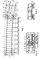
- FIG. 1 The plan view in Figure 1 shows the stock rails (1) welded to the movable switch rails (2) at point of tangency (3).
- the movable switch rails (2) are approximately 55 feet (16.8 m) long. They are held to gauge by the gauge rods (4) which are pivotally connected to the switch rails.
- Movement of the switch rails is controlled by a number of cranks (5), which are connected to the switch rails by connecting rods (6).
- the cranks (5) are operated by rotary hydraulic actuators (7). These actuators are mechanically connected in parallel by a synchronizing connecting rod (8).
- cranks (5) is maximum at the points (9) of the switch rails. Succeeding cranks to the left have successively decreasing throws, until at the point of tangency, the throw is theoretically zero. All the cranks move through an arc of 190 degrees to set the switch to the turnout or the straight-away position and provide an over-centre locking device. The crank throws, therefore, define the horizontal alignment of the switch rail in either the straight-through profile or the turnout direction.
- the straight-through fixed rails are designated (10), and the turnout fixed rails (11). These fixed rails are welded to the stock rails at (12) and (13) respectively. Axial rail tension or compression forces due to temperature fluctuation are transmitted through the switch points by means of the radius arm links (14). These links are connected to brackets (15) which project from cast sections in the switch rails and fixed rails, respectively. Beyond the brackets (15) on the frog side of the points, the track components and track geometry are identical with a standard #20 turnout.
- the instantaneous centres of the radius arms (14) are some distance to the left of the point of the switch, so that the latter, in moving, approximate the arcs of circles with centres about 27 feet (8.2 m) to the left of the switch points.
- the function of the radius arms is to make expensive expansion joints at the switch unnecessary.
- cranks have two extreme positions 190 degrees apart so that any lateral compressive force applied to the connecting rod, due to passage of a vehicle, will urge the piston into more forceful contact with the stop which already limits its motion.
- the converse is true for the other extreme position of the crank.
- the mechanism is therefore inherently self-locking in the sense that an external force cannot drive the system in reverse.
- the switch may be powered by a hydraulic power supply pack with electrically operated valve and signal logic.
- this first operates the hydraulic cylinders (19) to withdraw the locking pins from the switch points. It then operates the hydraulic crank actuators (7) to set the switch rails in their new position prior to a second operation of the locking cylinders (19) to relock the system.
- a secondary locking hydraulic cylinder can be installed in the rotary actuator synchronizing rod (8).
- Signalling is controlled by a system of light-emitting diode limit switches which will sense the integrity of the switch geometry, the register of the rail points, and the engagement of the locking rams before an all- clear signal is given. Failure of the system in any sense will generate a 'stop' signal.
- the butt switch by its very nature, provides a discontinuity in the rail, it is obvious that some means of supporting significant axial load in the stock rails must be provided if the switch is to be used in a continuously welded railway system subject to temperature variations. This could be done by providing an anchor at the point of tangency, a similar anchor on the frog side of the switch, and isolating the switch completely from the stock rails. Since the switch is a fairly long assembly, some means of compensating for expansion due to temperature changes should be provided, such as Conley joints. These are expansion joints and six per switch would be required. The cost of these is, however, very high.
- the rails should be laid between the mean temperature plus 15°F (8°C) and the mean temperature plus 25°F (14°C).
- the operating range for maximum rail stress is 80 plus 25°, that is 105°F (58°C).
- the stress associated with this temperature range is approximately 20,000 psi (138 MPa). Since the cross- sectional area of a 136 lb rail is 13.35 square inches (86 cm 2 ), the resulting axial load in the rail could be as high as 133.5 tons (1,188 kN) per rail. This means that the rail anchors provided on the stock rails have to be able to withstand such a longitudinal rail load.
- the switch rails may be welded to the stock rails at the point of tangency using the usual thermite welding process for in situ welding of continuous-welded rails.
- straight-through and turnout fixed rails of the switch may in turn be welded to the stock rails in a similar manner.
- the radius arm mechanism ensures that the gap at the point of the switch will be maintained to a close tolerance.
- the action of the radius arms provides for another very useful feature.
- the radius arms actually provide moments at the point ends of the switch rails. If the action of all the rotary actuators excepting the last one nearest the point of the switch is ignored, then the action of the couple provided by the radius arms will tend to provide a constant bending moment down the length of the switch rails to the point of tangency.
- the switch rails thus act as cantilever beams built-in at the point of tangency and loaded with couples at the ends. The resulting constant longitudinal bending moment would induce the rail to take up the profile of the true arc of a.circle. This profile is a requirement of specific designs of the switch, however the device is not limited to a specific profile. Any desired profile, i.e. a spiral can be provided.
- FIG. 5 Sections through the insert castings (26) are shown in Figure 5.
- An additional feature of the rail insert casting (26), adjacent to the point of the switch is a vertical registering device which keeps the rails in vertical register and also a horizontal registering device.
- the horizontal register is provided by a hydraulic ram (19) which locks the castings together in either the straight-away position or the turnout position by means of a locking pin (20).
- the vertical register is provided by an interlocking tongue (18) which projects from the casting at the point of the switch rails and engages with a slot (17) in the casting on the frog side of the point of the switch. This may be seen in Figure 3. Both registering systems are duplicated on each of the switch rails. It will be appreciated that as a train approaches the switch, approach rail (2) deflects somewhat and the tongue (18) signals that deflection to trailing side rail (10, 11) which also deflects somewhat, thereby reducing batter of the end of trailing side rail (10, 11).
- the radius arms (14) which transmit the axial load in the rails across the switch are weldments which are triangular in section.
- a section through the radius arms (14) is shown in Figure 6.
- the triangular section acts like a snowplow to break out any compacted snow or ice which may collect between the radius arms and the fixed rails of the switch.
- the radius arm pins (22, 23, 24, 25) are fitted with spherical bearings which permit the pivots to move vertically without jamming.
Landscapes
- Engineering & Computer Science (AREA)
- Mechanical Engineering (AREA)
- Architecture (AREA)
- Civil Engineering (AREA)
- Structural Engineering (AREA)
- Railway Tracks (AREA)
- Train Traffic Observation, Control, And Security (AREA)
- Force Measurement Appropriate To Specific Purposes (AREA)
Applications Claiming Priority (2)
| Application Number | Priority Date | Filing Date | Title |
|---|---|---|---|
| US575407 | 1984-01-30 | ||
| US06/575,407 US4534527A (en) | 1984-01-30 | 1984-01-30 | All weather switch for railroads |
Publications (2)
| Publication Number | Publication Date |
|---|---|
| EP0151012A2 true EP0151012A2 (fr) | 1985-08-07 |
| EP0151012A3 EP0151012A3 (fr) | 1987-04-01 |
Family
ID=24300197
Family Applications (1)
| Application Number | Title | Priority Date | Filing Date |
|---|---|---|---|
| EP85300548A Withdrawn EP0151012A3 (fr) | 1984-01-30 | 1985-01-25 | Aiguillage tout temps pour chemins de fer |
Country Status (5)
| Country | Link |
|---|---|
| US (1) | US4534527A (fr) |
| EP (1) | EP0151012A3 (fr) |
| JP (1) | JPS60242201A (fr) |
| AU (1) | AU568183B2 (fr) |
| CA (1) | CA1216921A (fr) |
Cited By (4)
| Publication number | Priority date | Publication date | Assignee | Title |
|---|---|---|---|---|
| WO1995002729A1 (fr) * | 1993-07-13 | 1995-01-26 | Bishop Arthur E | Aiguillages pour des systemes automatises de transport guide |
| RU2129183C1 (ru) * | 1996-05-15 | 1999-04-20 | Валов Владимир Васильевич | Стрелочный перевод |
| GB2336615A (en) * | 1998-04-24 | 1999-10-27 | F H Limited | Actuator for a rail switch and crossing system |
| GB2383068A (en) * | 2001-12-14 | 2003-06-18 | Balfour Beatty Plc | Forked railway track system |
Families Citing this family (8)
| Publication number | Priority date | Publication date | Assignee | Title |
|---|---|---|---|---|
| IT1242226B (it) * | 1990-10-10 | 1994-03-03 | Sasib Spa | Dispositivo di manovra per deviatoi ferroviari, in particolare per linee ad alta velocita' |
| US6243657B1 (en) | 1997-12-23 | 2001-06-05 | Pii North America, Inc. | Method and apparatus for determining location of characteristics of a pipeline |
| AT5706U1 (de) * | 2001-05-07 | 2002-10-25 | Vae Eisenbahnsysteme Gmbh | Verfahren zum einbauen von weichen in geleise sowie weiche zur durchführung dieses verfahrens |
| GB2435893B (en) * | 2006-03-09 | 2011-03-23 | Robert Windsor Simmons | A railway switch |
| GB2452307B (en) * | 2007-08-31 | 2012-06-06 | Neculai Mihalachi | The railway switch (point) with single elastic of traffic rails and load frame |
| US11155967B2 (en) * | 2016-04-13 | 2021-10-26 | Pandrol Limited | Swing turnout for railroad tracks and method for providing a turnout |
| FR3062404B1 (fr) * | 2017-01-31 | 2019-08-30 | Poma | Element d’aiguillage pour une voie de circulation d’un vehicule pneumatique, appareil de voie realise a partir de tels elements et procede de transport de passagers sur une voie equipee dudit appareil |
| DE102022202598B4 (de) | 2022-03-16 | 2024-02-15 | Bharat Forge CDP GmbH | Verbindungslasche |
Family Cites Families (5)
| Publication number | Priority date | Publication date | Assignee | Title |
|---|---|---|---|---|
| FR341986A (fr) * | 1903-07-21 | 1904-08-24 | Richard St George St George Mo | Perfectionnements dans les aiguillages de chemins de fer et de toutes voies ferrées |
| GB190423101A (en) * | 1904-10-26 | 1905-08-31 | Thomas Justus Saxton | Improvements in Railway Switches. |
| US3317725A (en) * | 1965-03-03 | 1967-05-02 | Railroad Permanent Way Product | Automatic yard switch |
| DE2817782C3 (de) * | 1978-04-22 | 1981-02-19 | Elektro-Thermit Gmbh, 1000 Berlin | Zungenweiche |
| AU566594B2 (en) * | 1983-06-29 | 1987-10-22 | Osredecki, V. | Switch for a railway turnout or crossing |
-
1984
- 1984-01-30 US US06/575,407 patent/US4534527A/en not_active Expired - Fee Related
-
1985
- 1985-01-22 CA CA000472541A patent/CA1216921A/fr not_active Expired
- 1985-01-23 AU AU38009/85A patent/AU568183B2/en not_active Withdrawn - After Issue
- 1985-01-25 EP EP85300548A patent/EP0151012A3/fr not_active Withdrawn
- 1985-01-29 JP JP60013655A patent/JPS60242201A/ja active Pending
Cited By (6)
| Publication number | Priority date | Publication date | Assignee | Title |
|---|---|---|---|---|
| WO1995002729A1 (fr) * | 1993-07-13 | 1995-01-26 | Bishop Arthur E | Aiguillages pour des systemes automatises de transport guide |
| AU674429B2 (en) * | 1993-07-13 | 1996-12-19 | Arthur Ernest Bishop | Switches for automated guideway transit systems |
| US5657696A (en) * | 1993-07-13 | 1997-08-19 | Bishop; Arthur Ernest | Switches for automated guideway transit systems |
| RU2129183C1 (ru) * | 1996-05-15 | 1999-04-20 | Валов Владимир Васильевич | Стрелочный перевод |
| GB2336615A (en) * | 1998-04-24 | 1999-10-27 | F H Limited | Actuator for a rail switch and crossing system |
| GB2383068A (en) * | 2001-12-14 | 2003-06-18 | Balfour Beatty Plc | Forked railway track system |
Also Published As
| Publication number | Publication date |
|---|---|
| JPS60242201A (ja) | 1985-12-02 |
| EP0151012A3 (fr) | 1987-04-01 |
| AU568183B2 (en) | 1987-12-17 |
| US4534527A (en) | 1985-08-13 |
| CA1216921A (fr) | 1987-01-20 |
| AU3800985A (en) | 1985-08-08 |
Similar Documents
| Publication | Publication Date | Title |
|---|---|---|
| US4534527A (en) | All weather switch for railroads | |
| EP1387905B1 (fr) | Procede pour le montage d'aiguillages dans des voies, ainsi qu'aiguillage pour l'execution de ce procede | |
| US11155967B2 (en) | Swing turnout for railroad tracks and method for providing a turnout | |
| DE3709619C2 (fr) | ||
| KR102096004B1 (ko) | 굴절형 편심 웨브를 갖는 조립식 철도교 | |
| US5191838A (en) | Rail clip applicator and method of applying rail clips | |
| US4210300A (en) | Point switch | |
| GB2075578A (en) | Railway points | |
| EP3152093B1 (fr) | Véhicule ferroviaire à trémie | |
| CA2381638A1 (fr) | Support a travees multiples | |
| CN216040444U (zh) | 一种有轨电车道岔转辙结构 | |
| EP0130783A2 (fr) | Un aiguillage pour une déviation ou un croisement de chemin de fer | |
| US3819935A (en) | Railway switch for vignoles rails | |
| CN219297940U (zh) | 一种用于开启桥的梁端钢轨伸缩装置 | |
| DE3004406C2 (fr) | ||
| US7104508B1 (en) | Spring loaded throw rod | |
| EP1169517A1 (fr) | Aiguillage pivotant pour rampe de guidage | |
| US20020060273A1 (en) | Sleeper arrangement for railroad switch | |
| US3317725A (en) | Automatic yard switch | |
| RU231932U1 (ru) | Железобетонная шпала | |
| US770614A (en) | Moore | |
| US9145647B2 (en) | Folding switch | |
| US1258253A (en) | Insulated rail-joint. | |
| US606339A (en) | Railroad-crossing | |
| CN121161665A (zh) | 一种新型矿山轨道道岔 |
Legal Events
| Date | Code | Title | Description |
|---|---|---|---|
| PUAI | Public reference made under article 153(3) epc to a published international application that has entered the european phase |
Free format text: ORIGINAL CODE: 0009012 |
|
| AK | Designated contracting states |
Designated state(s): AT BE DE FR GB IT SE |
|
| PUAL | Search report despatched |
Free format text: ORIGINAL CODE: 0009013 |
|
| AK | Designated contracting states |
Kind code of ref document: A3 Designated state(s): AT BE DE FR GB IT SE |
|
| 17P | Request for examination filed |
Effective date: 19870903 |
|
| STAA | Information on the status of an ep patent application or granted ep patent |
Free format text: STATUS: THE APPLICATION IS DEEMED TO BE WITHDRAWN |
|
| 18D | Application deemed to be withdrawn |
Effective date: 19880802 |
|
| RIN1 | Information on inventor provided before grant (corrected) |
Inventor name: PERLIN, SEMION Inventor name: VAN EYKEN, LAWRENCE A. J. |