EP0151070A2 - Selbsttätig nachstellende Bremsbetätigungsvorrichtung - Google Patents
Selbsttätig nachstellende Bremsbetätigungsvorrichtung Download PDFInfo
- Publication number
- EP0151070A2 EP0151070A2 EP85400109A EP85400109A EP0151070A2 EP 0151070 A2 EP0151070 A2 EP 0151070A2 EP 85400109 A EP85400109 A EP 85400109A EP 85400109 A EP85400109 A EP 85400109A EP 0151070 A2 EP0151070 A2 EP 0151070A2
- Authority
- EP
- European Patent Office
- Prior art keywords
- brake motor
- control part
- nut
- screw
- piston
- Prior art date
- Legal status (The legal status is an assumption and is not a legal conclusion. Google has not performed a legal analysis and makes no representation as to the accuracy of the status listed.)
- Granted
Links
Images

Classifications
-
- F—MECHANICAL ENGINEERING; LIGHTING; HEATING; WEAPONS; BLASTING
- F16—ENGINEERING ELEMENTS AND UNITS; GENERAL MEASURES FOR PRODUCING AND MAINTAINING EFFECTIVE FUNCTIONING OF MACHINES OR INSTALLATIONS; THERMAL INSULATION IN GENERAL
- F16D—COUPLINGS FOR TRANSMITTING ROTATION; CLUTCHES; BRAKES
- F16D65/00—Parts or details
- F16D65/38—Slack adjusters
- F16D65/40—Slack adjusters mechanical
- F16D65/52—Slack adjusters mechanical self-acting in one direction for adjusting excessive play
- F16D65/56—Slack adjusters mechanical self-acting in one direction for adjusting excessive play with screw-thread and nut
- F16D65/567—Slack adjusters mechanical self-acting in one direction for adjusting excessive play with screw-thread and nut for mounting on a disc brake
Definitions
- the invention relates to a brake motor capable of applying a brake, in particular intended to equip a motor vehicle.
- the invention relates in particular to an automatically adjustable brake motor intended to automatically compensate for the wear of the friction linings in order to maintain the stroke of the mechanical control and / or of the brake pedal at a substantially constant and low level.
- the automatic adjustment comprises a screw-nut system with reversible pitch, the nut being free to rotate to follow the movements of the piston, the nut being blocked for the reverse movement by means of a friction clutch spring placed between the piston and the nut.
- This arrangement allows an axial force to be transmitted between a control part and the working piston through this blocking device formed by the clutch spring.
- the automatic adjustment is implemented when the working piston is hydraulically biased, the automatic adjustment being out of service during the mechanical actuation because in this case the screw and the nut move simultaneously and cannot set in motion. performs automatic adjustment.
- the invention provides an automatic adjustment brake motor of simple and reliable construction with or without hydraulic control and without the drawbacks mentioned above.
- the invention provides an automatic adjustment brake motor of the type comprising a screw-nut system with reversible pitch placed between a working piston and a control part and capable of transmitting an axial force from said control part. to said working piston when the relative rotation between screw and nut of the screw-nut system is blocked by a blocking device characterized in that the brake motor comprises an automatic device for relative axial positioning between said control part and said working piston ensuring a predetermined approach stroke between said working piston and a friction element capable of being biased by the brake motor.
- the automatic relative axial positioning device makes it possible to make up for the clearances between the working piston and the friction element without any obligation to "pump" and the mechanical control is effective immediately whatever the initial distance between the working piston and the friction element to be requested.
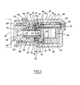
- the brake motor shown in FIG. 1 is of the corner control type used in particular in heavy-duty disc brakes.
- This brake motor comprises, in a conventional manner, a body 20 in which is mounted a guide piece 22, fixed by relative to the body 20, and which receives a corner 24 and two rollers 26 and 28 placed on either side of the corner 24.
- the roller 26 is capable of cooperating with the bottom 30 of a cut formed in the part 22.
- D in a similar way the roller 28 is capable of cooperating with the bottom 32 of a control piece 34 slidably mounted in a bore 36 formed in the body 20.
- a control piece 34 In the control piece 34 is formed a bore 38 in which is slidably mounted a working piston 40 capable of cooperating with a friction element 42 represented symbolically in dotted lines.
- An automatic adjustment device designated as a whole by the reference 44 is placed between the piston 40 and the control part 34. More specifically, a screw 46 with reversible pitch is fixed in the piston 44 and carries a nut 48 also with reversible pitch which cooperates through a cone portion 50 formed on a flat portion 52 of the nut 48 with a cone portion of conjugate shape 54 formed on the bottom of the bore 38 of the control part 34. The cone friction on the cone, the portions 50 and 54 form a device for blocking the rotation of the nut 48.
- the brake motor comprises an automatic device for axial relative positioning between the control part and the working piston, generally designated by the reference 56.
- This positioning device 56 comprises on the one hand means internal 58 capable of displacing the piston 40 on the left with reference to FIG. 1 and formed in the embodiment represented by a first spring mounted prestressed, and on the other hand a second blocking device designated as a whole by the reference 60.
- This second blocking device 60 comprises a friction ring 62 slidably mounted on straight grooves 64 formed on the outside diameter of the nut 48. the friction ring 62 having tongues which penetrate into the grooves 64 so as to rotationally secure said friction ring relative to the nut 48.
- the second blocking device further comprises two parts placed on either side of the friction ring 62, a first 66 formed by a rod mounted in a bore 68 formed in the bottom of the control part 34, as seen in Fig. l, the part 66 has a length such that it cooperates on the one hand with the friction ring 62 and on the other hand with a fixed part relative to the body 20 and more precisely with a front wall 70 of the part guide 22, the part 66 being capable of sliding the other of said two parts formed by in the hole 68.
- the control part 34 also carries / a sliding ring 72 immobilized in rotation relative to the control part 34 by means of folded tabs 74 penetrating into openings formed in a washer 76 fixed relative to the control piece 34 by means of a ring 78 placed in a groove in the control piece 34.
- the ring 78 is placed so that when the brake is at rest as shown in FIG. 1 there is a small clearance between the part 72 and the rod 78 thus defining said predetermined initial stroke, the rod 78 forming a fixed stop to the other part 72 when the brake is applied.
- the open portion 52 of the nut 48 is capable of cooperating with the fixed stop 78 through the ring 76 by means of a ball stop 80 forming an axial bearing.
- the brake motor also includes a device for resetting the automatic adjustment, generally designated by the reference 84 and formed in the embodiment represented by a rod 86 having a first end 88 on which is formed an operating head 90 and at its other end 92 a toothing 94 capable of cooperating with a toothing 96 formed on the periphery of the open portion 52 of the nut 48.
- a spring of rod return 98 is placed between the guide piece 22 and a flange carried by the rod 86 so as to release the two teeth from one another when the operating head 90 is not biased to the left while moving still referring to FIG. 1.
- a screw 100 mounted in the body 20 carries a projection 102 which passes through a lumen 104 formed in the control part 34 and penetrates into a groove 106 formed in the working piston 40 thus preventing any movement of the piston and the control part. rotation relative to the body 20 but allowing the translational movements in the axial direction.
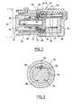
- FIG. 3 it can be seen that four parts 66 have been provided so as to urge the friction ring 62 at several points on its periphery and prevent this ring from getting crooked.
- the pieces 66 are spaced in the up-down direction of FIG. 3 so as to pass on either side of the roller 28 in order to be able to be applied to the guide piece 22.
- the piston 40 thanks to the automatic positioning device spontaneously catches up with all the play existing between the piston and the friction elements without requiring a large stroke at the corner or at the control part 34, this regardless of the relative position of the piston 40 of the control part 34 and of the friction element 42.
- Fig. 2 shows a second embodiment, in which the same elements fulfilling the same functions will have the same references.
- This embodiment differs from the previous one only by a variant of the arrangement of the second locking device which alone will be described in the following, for the rest of the description refer to the description of the first embodiment.
- the friction ring 62 is carried by the toothing formed on the open portion 52 of the nut 48.
- This toothing fulfills the function of the straight grooves 64 of the first embodiment and also performs the function of the toothing 96 of the first embodiment, intended for the reset device 84.
- the friction ring 62 is free to slide axially on this toothing 64-96 and it is placed between the two parts 66, 72, namely the rod 66 able to slide in the room 34 and the other part 72, the folded legs 74 of which serve on the one hand to immobilize said other part 72 in rotation relative to the control part 34 by cooperation with openings formed in the washer 76, these lugs 74 also cooperating with the friction ring 62 to immobilize the latter in rotation as indicated in the first embodiment.
- the axial play between the other part 72 and the fixed stop washer 76 defines the predetermined initial stroke in a similar manner to the first embodiment.
- Figs. 4 and 5 there is a third embodiment of which is an embodiment which is a variant of the brake motor according to the invention, in which the control of the brake motor instead of being done by means of a wedge and rollers, is carried out by means of a purely hydraulic control.
- the brake motor comprises a body 20 in which is formed a bore 108 which receives a hydraulic piston 110 mounted in leaktight manner in said bore 108 by means of a conventional seal 112.
- the bottom of the body 20, the bore 108 and the piston 110 define a chamber 114 capable of being connected to a source of hydraulic pressure (not shown) such as for example the master cylinder of the vehicle.
- the body 20 also receives a control piece 34 capable of sliding in a bore 36 formed in said body 20.
- the control piece receives a working piston 40 which similarly carries a screw with reversible pitch 46 on which is mounted a nut also with reversible pitch 48.
- the nut 48 has straight longitudinal grooves 64 on which a friction ring 62 can slide but is integral in rotation with said nut.
- the friction disc can be blocked between two parts, a first 66 'formed by two tabs integral with a ring 66 "itself immobilized relative to the body 20 by means of cutouts 66"' as shown in FIG. 5 and another part 72 urged into friction engagement with said friction ring 62 through a spring 58.
- Said other part 72 is immobilized in rotation relative to the control part 34 by means of lugs 116 penetrating into notches 118 formed in a stop piece 76 integral with the control piece 34.
- the stop piece 76 has four notches 118, two shallow 118 ', the bottom of these notches 118' defining with the tabs 116 of the piece 72 the predetermined approach stroke as indicated in the previous embodiments.
- the part 76 has two other notches 118 "deep and extending over the web of the part 76 so as to allow the passage of the two tabs 66 'allowing the latter to cooperate with the friction ring 62.
- the friction ring 62 and the two parts 72 and 66 ′ have teeth to ensure high friction between the parts.
- the expanded portion 52 of nut 48 present
- this embodiment also comprises a reset device 84, it is nevertheless mounted perpendicular to the axis of the brake motor and also has a rod 86 provided at one of its ends with an operating head 90 formed by a screwdriver slot and at its other end a toothing 94 capable of cooperating with a toothing 96 when the rod 86 is pushed by the screwdriver against the spring 98 which normally keeps the two toothing apart one from the other in the absence of thrust on the rod 86.
- this brake motor is double with a working piston on each side of the brake motor and it is then possible to use the invention on a drum brake to actuate two segments.
- the spring 58 which moves the working piston 40 to make up for the clearances must have a force greater than the force of the return spring of the segments placed between them to return the segments to their initial rest position after the end of application of the braking.
- a brake motor simultaneously comprising a hydraulic control of the type of the third embodiment and a mechanical control of the type used on the first two embodiments provided that the interface is properly arranged between the piston 110 and the control part 34 to interpose the mechanical control in an area not comprising hydraulic pressure.
Landscapes
- Engineering & Computer Science (AREA)
- General Engineering & Computer Science (AREA)
- Mechanical Engineering (AREA)
- Braking Arrangements (AREA)
- Transmission Devices (AREA)
Applications Claiming Priority (2)
| Application Number | Priority Date | Filing Date | Title |
|---|---|---|---|
| FR8401438A FR2558910A1 (fr) | 1984-01-31 | 1984-01-31 | Moteur de frein a reglage automatique |
| FR8401438 | 1984-01-31 |
Publications (3)
| Publication Number | Publication Date |
|---|---|
| EP0151070A2 true EP0151070A2 (de) | 1985-08-07 |
| EP0151070A3 EP0151070A3 (en) | 1985-09-18 |
| EP0151070B1 EP0151070B1 (de) | 1988-04-13 |
Family
ID=9300609
Family Applications (1)
| Application Number | Title | Priority Date | Filing Date |
|---|---|---|---|
| EP85400109A Expired EP0151070B1 (de) | 1984-01-31 | 1985-01-23 | Selbsttätig nachstellende Bremsbetätigungsvorrichtung |
Country Status (7)
| Country | Link |
|---|---|
| US (1) | US4699253A (de) |
| EP (1) | EP0151070B1 (de) |
| JP (2) | JPS60179537A (de) |
| BR (1) | BR8500382A (de) |
| DE (1) | DE3562159D1 (de) |
| ES (1) | ES8606592A1 (de) |
| FR (1) | FR2558910A1 (de) |
Cited By (2)
| Publication number | Priority date | Publication date | Assignee | Title |
|---|---|---|---|---|
| EP0271864A3 (en) * | 1986-12-18 | 1989-03-29 | Lucas Industries Public Limited Company | Actuating mechanism with an automatic adjustment for brakes, especially for juggernauts |
| FR2697880A1 (fr) * | 1992-11-06 | 1994-05-13 | Peugeot | Dispositif de rattrapage de jeu pour frein à tambour et frein muni d'un tel dispositif. |
Families Citing this family (5)
| Publication number | Priority date | Publication date | Assignee | Title |
|---|---|---|---|---|
| DE19711851B4 (de) * | 1997-03-21 | 2005-09-22 | Continental Teves Ag & Co. Ohg | Bremsaktuator mit Feststellbremse für eine elektrische Bremsanlage |
| WO2004027282A1 (de) * | 2002-09-17 | 2004-04-01 | Continental Teves Ag & Co. Ohg | Hydraulische fahrzeugbremse |
| ATE528530T1 (de) * | 2007-03-21 | 2011-10-15 | Haldex Brake Prod Ab | Scheibenbremse |
| WO2014106672A1 (en) * | 2014-04-04 | 2014-07-10 | Haldex Brake Products Ab | Brake actuation mechanism for a disc brake and disc brake comprising the same |
| WO2025007204A1 (pt) * | 2023-07-06 | 2025-01-09 | Instituto Hercílio Randon | Mecanismo de compensação de desgaste de par tribológico de frenagem, processo de fabricação de mecanismo de compensação de desgaste, sistema de acionamento de freio e veículo |
Family Cites Families (12)
| Publication number | Priority date | Publication date | Assignee | Title |
|---|---|---|---|---|
| FR1317919A (de) * | 1963-05-10 | |||
| GB993686A (en) * | 1963-12-20 | 1965-06-02 | Bromsregulator Svenska Ab | Improvements in automatic slack adjusters for vehicle brake linkages |
| GB1269917A (en) * | 1971-01-12 | 1972-04-06 | Bromsregulator Svenska Ab | Improvements in pneumatic cylinder-piston units for railway vehicle brake riggings |
| DE2337420C2 (de) * | 1973-07-23 | 1982-06-16 | Knorr-Bremse, 1000 Berlin und 8000 München | Selbsttätige Bremsgestänge-Nachstellvorrichtung, insbesondere für Schienenfahrzeugbremsen |
| US3995722A (en) * | 1975-02-18 | 1976-12-07 | Abex Corporation | Fail-safe disc brake having a slack adjuster mechanism |
| US3967705A (en) * | 1975-04-02 | 1976-07-06 | The Bendix Corporation | Application adjuster for disc brake |
| GB1540084A (en) * | 1975-04-08 | 1979-02-07 | Girling Ltd | Automatic adjusters for vehicle brakes |
| FR2434310A1 (fr) * | 1978-08-24 | 1980-03-21 | Pont A Mousson | Mecanisme de commande de frein a disque |
| JPS55100434A (en) * | 1979-01-22 | 1980-07-31 | Akebono Brake Ind Co Ltd | Gap adjuster for disc brake |
| US4399894A (en) * | 1979-02-14 | 1983-08-23 | Kelsey-Hayes Company | Push rod slack adjuster |
| DE3011713C2 (de) * | 1980-03-26 | 1982-11-11 | Knorr-Bremse GmbH, 8000 München | Bremszylinder für Reibungsbremsen von Fahrzeugen, insbesondere Schienenfahrzeugen |
| US4394890A (en) * | 1981-08-03 | 1983-07-26 | Eaton Corporation | Automatic slack adjuster |
-
1984
- 1984-01-31 FR FR8401438A patent/FR2558910A1/fr active Pending
-
1985
- 1985-01-23 EP EP85400109A patent/EP0151070B1/de not_active Expired
- 1985-01-23 DE DE8585400109T patent/DE3562159D1/de not_active Expired
- 1985-01-29 JP JP60013675A patent/JPS60179537A/ja active Pending
- 1985-01-29 BR BR8500382A patent/BR8500382A/pt not_active IP Right Cessation
- 1985-01-30 ES ES539971A patent/ES8606592A1/es not_active Expired
-
1987
- 1987-02-05 US US07/015,494 patent/US4699253A/en not_active Expired - Fee Related
-
1993
- 1993-05-10 JP JP029643U patent/JPH0647743U/ja active Pending
Cited By (2)
| Publication number | Priority date | Publication date | Assignee | Title |
|---|---|---|---|---|
| EP0271864A3 (en) * | 1986-12-18 | 1989-03-29 | Lucas Industries Public Limited Company | Actuating mechanism with an automatic adjustment for brakes, especially for juggernauts |
| FR2697880A1 (fr) * | 1992-11-06 | 1994-05-13 | Peugeot | Dispositif de rattrapage de jeu pour frein à tambour et frein muni d'un tel dispositif. |
Also Published As
| Publication number | Publication date |
|---|---|
| DE3562159D1 (en) | 1988-05-19 |
| ES539971A0 (es) | 1986-04-01 |
| JPS60179537A (ja) | 1985-09-13 |
| FR2558910A1 (fr) | 1985-08-02 |
| EP0151070B1 (de) | 1988-04-13 |
| JPH0647743U (ja) | 1994-06-28 |
| EP0151070A3 (en) | 1985-09-18 |
| BR8500382A (pt) | 1985-09-10 |
| US4699253A (en) | 1987-10-13 |
| ES8606592A1 (es) | 1986-04-01 |
Similar Documents
| Publication | Publication Date | Title |
|---|---|---|
| EP1350040B1 (de) | Scheibenbremsenzylinder mit feststellbremsmechanismus | |
| EP0145535B1 (de) | Automatisch regulierter Bremsmotor | |
| EP0743053A1 (de) | Sicherheits- und Kontrollvorrichtung der Verriegelung einer Radnabe, insbesondere für Rollstuhl | |
| EP0113261B1 (de) | Automatisch nachstellende Scheibenbremse | |
| EP0151070B1 (de) | Selbsttätig nachstellende Bremsbetätigungsvorrichtung | |
| EP0186537B1 (de) | Scheibenbremse | |
| EP0734496B1 (de) | Automatisch nachstellbare strebe für eine trommelbremse | |
| FR2537230A2 (fr) | Dispositif de reglage automatique pour frein | |
| FR2493943A1 (fr) | Dispositif de freinage pour vehicules a rattrapage de jeu automatique | |
| FR2600734A1 (fr) | Dispositif de reglage automatique pour frein a disque. | |
| FR2800825A1 (fr) | Rampe a billes et cylindre de freins comportant une telle rampe | |
| EP0128081B1 (de) | Automatisch regulierter Bremsmotor | |
| EP0175600B1 (de) | Nachstellvorrichtung für Scheibenbremse | |
| FR2778712A1 (fr) | Dispositif de rattrapage d'usure notamment pour un frein de vehicule | |
| FR2849136A1 (fr) | Moteur de frein a disque a rattrapage d'usure, et frein a disque equipe d'un tel moteur | |
| EP1119707B1 (de) | Kraftfahrzeug-anlasser mit reibungsantrieb | |
| EP0319358B1 (de) | Trommelbremse mit selbsttätiger Nachstellung | |
| EP1412655B1 (de) | Scheibenbremse für kratfahrzeuge mit nachstellvorrichtung des belagverschleisses | |
| EP0484191B1 (de) | Selbstnachstellender Bremsmotor | |
| FR2569798A1 (fr) | Frein a disque a reglage automatique | |
| FR2875877A1 (fr) | Frein de service et de blocage de vehicule automobile et verrou a liaison de force pour un tel frein | |
| FR2524591A1 (fr) | Dispositif de reglage et de controle d'un cable de commande pour un frein a tambour et frein a tambour incorporant un tel dispositif de reglage | |
| FR2504627A1 (fr) | Frein a tambour a machoires internes actionnable hydrauliquement | |
| FR2530759A2 (fr) | Frein a tambour a reglage automatique | |
| FR2572483A1 (fr) | Frein a disque a reglage automatique |
Legal Events
| Date | Code | Title | Description |
|---|---|---|---|
| PUAI | Public reference made under article 153(3) epc to a published international application that has entered the european phase |
Free format text: ORIGINAL CODE: 0009012 |
|
| PUAL | Search report despatched |
Free format text: ORIGINAL CODE: 0009013 |
|
| 17P | Request for examination filed |
Effective date: 19850131 |
|
| AK | Designated contracting states |
Kind code of ref document: A2 Designated state(s): DE FR GB IT NL SE |
|
| AK | Designated contracting states |
Kind code of ref document: A3 Designated state(s): DE FR GB IT NL SE Designated state(s): DE FR GB IT NL SE |
|
| RAP1 | Party data changed (applicant data changed or rights of an application transferred) |
Owner name: BENDIX FRANCE |
|
| RAP1 | Party data changed (applicant data changed or rights of an application transferred) |
Owner name: BENDIX FRANCE |
|
| 17Q | First examination report despatched |
Effective date: 19870224 |
|
| ITF | It: translation for a ep patent filed | ||
| GRAA | (expected) grant |
Free format text: ORIGINAL CODE: 0009210 |
|
| AK | Designated contracting states |
Kind code of ref document: B1 Designated state(s): DE FR GB IT NL SE |
|
| REF | Corresponds to: |
Ref document number: 3562159 Country of ref document: DE Date of ref document: 19880519 |
|
| GBT | Gb: translation of ep patent filed (gb section 77(6)(a)/1977) | ||
| PLBE | No opposition filed within time limit |
Free format text: ORIGINAL CODE: 0009261 |
|
| STAA | Information on the status of an ep patent application or granted ep patent |
Free format text: STATUS: NO OPPOSITION FILED WITHIN TIME LIMIT |
|
| 26N | No opposition filed | ||
| ITTA | It: last paid annual fee | ||
| EAL | Se: european patent in force in sweden |
Ref document number: 85400109.6 |
|
| PGFP | Annual fee paid to national office [announced via postgrant information from national office to epo] |
Ref country code: FR Payment date: 19960112 Year of fee payment: 12 |
|
| PGFP | Annual fee paid to national office [announced via postgrant information from national office to epo] |
Ref country code: GB Payment date: 19960115 Year of fee payment: 12 |
|
| PGFP | Annual fee paid to national office [announced via postgrant information from national office to epo] |
Ref country code: SE Payment date: 19960119 Year of fee payment: 12 |
|
| PGFP | Annual fee paid to national office [announced via postgrant information from national office to epo] |
Ref country code: DE Payment date: 19960126 Year of fee payment: 12 |
|
| PGFP | Annual fee paid to national office [announced via postgrant information from national office to epo] |
Ref country code: NL Payment date: 19960130 Year of fee payment: 12 |
|
| PG25 | Lapsed in a contracting state [announced via postgrant information from national office to epo] |
Ref country code: GB Effective date: 19970123 |
|
| PG25 | Lapsed in a contracting state [announced via postgrant information from national office to epo] |
Ref country code: SE Effective date: 19970124 |
|
| PG25 | Lapsed in a contracting state [announced via postgrant information from national office to epo] |
Ref country code: NL Effective date: 19970801 |
|
| GBPC | Gb: european patent ceased through non-payment of renewal fee |
Effective date: 19970123 |
|
| PG25 | Lapsed in a contracting state [announced via postgrant information from national office to epo] |
Ref country code: FR Effective date: 19970930 |
|
| NLV4 | Nl: lapsed or anulled due to non-payment of the annual fee |
Effective date: 19970801 |
|
| PG25 | Lapsed in a contracting state [announced via postgrant information from national office to epo] |
Ref country code: DE Effective date: 19971001 |
|
| EUG | Se: european patent has lapsed |
Ref document number: 85400109.6 |
|
| REG | Reference to a national code |
Ref country code: FR Ref legal event code: ST |