EP0151214A2 - Brûleur pour combustibles liquides du type à vaporisation - Google Patents
Brûleur pour combustibles liquides du type à vaporisation Download PDFInfo
- Publication number
- EP0151214A2 EP0151214A2 EP84110376A EP84110376A EP0151214A2 EP 0151214 A2 EP0151214 A2 EP 0151214A2 EP 84110376 A EP84110376 A EP 84110376A EP 84110376 A EP84110376 A EP 84110376A EP 0151214 A2 EP0151214 A2 EP 0151214A2
- Authority
- EP
- European Patent Office
- Prior art keywords
- evaporator
- evaporator pot
- recesses
- burner
- pot
- Prior art date
- Legal status (The legal status is an assumption and is not a legal conclusion. Google has not performed a legal analysis and makes no representation as to the accuracy of the status listed.)
- Granted
Links
Images
Classifications
-
- F—MECHANICAL ENGINEERING; LIGHTING; HEATING; WEAPONS; BLASTING
- F23—COMBUSTION APPARATUS; COMBUSTION PROCESSES
- F23D—BURNERS
- F23D11/00—Burners using a direct spraying action of liquid droplets or vaporised liquid into the combustion space
- F23D11/36—Details
- F23D11/44—Preheating devices; Vaporising devices
- F23D11/441—Vaporising devices incorporated with burners
- F23D11/443—Vaporising devices incorporated with burners heated by the main burner flame
-
- F—MECHANICAL ENGINEERING; LIGHTING; HEATING; WEAPONS; BLASTING
- F23—COMBUSTION APPARATUS; COMBUSTION PROCESSES
- F23D—BURNERS
- F23D11/00—Burners using a direct spraying action of liquid droplets or vaporised liquid into the combustion space
- F23D11/04—Burners using a direct spraying action of liquid droplets or vaporised liquid into the combustion space the spraying action being obtained by centrifugal action
- F23D11/06—Burners using a direct spraying action of liquid droplets or vaporised liquid into the combustion space the spraying action being obtained by centrifugal action using a horizontal shaft
-
- F—MECHANICAL ENGINEERING; LIGHTING; HEATING; WEAPONS; BLASTING
- F23—COMBUSTION APPARATUS; COMBUSTION PROCESSES
- F23D—BURNERS
- F23D11/00—Burners using a direct spraying action of liquid droplets or vaporised liquid into the combustion space
- F23D11/005—Burners using a direct spraying action of liquid droplets or vaporised liquid into the combustion space with combinations of different spraying or vaporising means
Definitions
- the invention relates to a burner for liquid fuels of the evaporator type with the features of the preamble of claim 1.
- Such a burner is known from DE-OS 26 49 669. It has proven itself on the whole and, with a sufficient excess of air, provides a good mixture of fuel and combustion air, which is reflected in a blue flame. However, a high excess of air is not permissible for continuous operation, since the C0 2 value and thus the combustion efficiency does not meet the requirements and the excess air disturbs the thermal balance so that the dreaded condensation occurs on the rear wall.
- the invention has for its object to improve the generic burner in such a way that the oil vapor is mixed well with the fresh air and the combustion gas without affecting the injector effect. This object is achieved by the features of claim 1. Advantageous embodiments of the invention are characterized by the subclaims.
- a part of the oil vapor produced in the evaporator pot is introduced into the air stream in fine jets through the bore or slots before it emerges from the outlet opening.
- the media penetrate each other at an angle of incidence of approximately 90 ° . This angle of incidence, reinforced by the centrifugal force at the outlet of the evaporator pot, brings about an almost complete mixing of the oil vapor with the fresh air and the combustion gas.
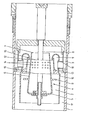
- the drawing shows the longitudinal section through a burner according to the invention.
- the burner has a housing 1, in which a cylindrical combustion chamber 2 is arranged, the ankihrem rear end closed by an end wall and limited by a flame tube 16.
- An air duct 3 is provided between the housing 1 and the combustion chamber 2 and is supplied with combustion air via an air connection (not shown) at the rear end of the housing 1.
- a rotationally symmetrical evaporator pot 4 is arranged within the combustion chamber 2 with a radial pitch.
- the evaporator pot 4 has a closed base 5, which is followed by a conically tapered jacket 6.
- the bottom 5 of the evaporator pot 4 is opposite an outlet opening 7 which is arranged at an axial distance from the end wall of the combustion chamber 2.
- Inside the evaporator pot 4 opens into a fuel supply line, not shown.
- the evaporator pot 4 is connected to a shaft 8 which is engaged by a drive, not shown, via which the evaporator pot 4 is set in rotation.
- a baffle plate 9 is arranged on the jacket 6 of the evaporator pot 4.
- a plurality of air inlet pipes 10 are inserted, which connect the air duct 3 to a deflection chamber 11.
- the deflection chamber 11 has the shape of an annular neck injector and has an annular outlet slot 12.
- An injector channel 13 is formed between the deflection chamber 11 and the jacket 6 of the evaporator pot.
- a flue gas duct 17 is provided between the flame tube 16 of the combustion chamber 2 and the wall of the housing 1 or the air duct 3. The flue gas duct 17 is arranged so that flue gas can be drawn in through the injector.
- the jacket 6 of the evaporator pot 4 which are formed, for example, by bores 14 or slots.
- the holes 14 are distributed in several rows over the circumference of the evaporator pot 4 and are provided in an area which is identified by the dash-dotted lines 15. This area lies between the outlet opening 7 of the evaporator pot and the baffle plate 9, preferably in the part of the injector channel 13 through which there is an axial flow .
- the emerging oil vapor jets penetrate the medium flowing through the injector channel 13.
- the diameter of the holes 14 should have a certain value of z. B. do not exceed 2.7 mm, so that no selectively dense oil vapor concentrations and concentrations occur. As shown, three rows of holes, each with twelve holes, are advantageously provided.
- an area ratio of the outlet cross sections of all the bores 14 to the outlet cross section of the outlet opening 7 of the evaporator pot 4 of 0.2 to 0.3 complied with.
- a ratio of 0.26 was chosen with a diameter of the outlet opening 7 of 33 mm and the shaft 8 of 10 mm. With a total throughput of 1 kg of heating oil per hour, only 1/20 to 1/10 of the amount of oil flows through the bores 14.
Landscapes
- Engineering & Computer Science (AREA)
- Chemical & Material Sciences (AREA)
- Combustion & Propulsion (AREA)
- Mechanical Engineering (AREA)
- General Engineering & Computer Science (AREA)
- Vaporization, Distillation, Condensation, Sublimation, And Cold Traps (AREA)
- Pressure-Spray And Ultrasonic-Wave- Spray Burners (AREA)
- Spray-Type Burners (AREA)
- Evaporation-Type Combustion Burners (AREA)
Priority Applications (1)
| Application Number | Priority Date | Filing Date | Title |
|---|---|---|---|
| AT84110376T ATE27351T1 (de) | 1983-12-22 | 1984-08-31 | Brenner fuer fluessige brennstoffe vom verdampfertyp. |
Applications Claiming Priority (2)
| Application Number | Priority Date | Filing Date | Title |
|---|---|---|---|
| DE19833346431 DE3346431A1 (de) | 1983-12-22 | 1983-12-22 | Brenner fuer fluessige brennstoffe vom verdampfertyp |
| DE3346431 | 1983-12-22 |
Publications (3)
| Publication Number | Publication Date |
|---|---|
| EP0151214A2 true EP0151214A2 (fr) | 1985-08-14 |
| EP0151214A3 EP0151214A3 (en) | 1986-02-05 |
| EP0151214B1 EP0151214B1 (fr) | 1987-05-20 |
Family
ID=6217714
Family Applications (1)
| Application Number | Title | Priority Date | Filing Date |
|---|---|---|---|
| EP84110376A Expired EP0151214B1 (fr) | 1983-12-22 | 1984-08-31 | Brûleur pour combustibles liquides du type à vaporisation |
Country Status (3)
| Country | Link |
|---|---|
| EP (1) | EP0151214B1 (fr) |
| AT (1) | ATE27351T1 (fr) |
| DE (2) | DE3346431A1 (fr) |
Cited By (1)
| Publication number | Priority date | Publication date | Assignee | Title |
|---|---|---|---|---|
| EP0595419A1 (fr) * | 1992-10-30 | 1994-05-04 | Shell Internationale Researchmaatschappij B.V. | Brûleur à combustible liquide |
Families Citing this family (2)
| Publication number | Priority date | Publication date | Assignee | Title |
|---|---|---|---|---|
| ATE60419T1 (de) * | 1987-03-13 | 1991-02-15 | Fuellemann Patent Ag | Brenner. |
| US5015173A (en) * | 1988-06-09 | 1991-05-14 | Vth Ag Verfahrenstechnik Fur Heizung | Burner for the combustion of liquids in the gaseous state |
Family Cites Families (4)
| Publication number | Priority date | Publication date | Assignee | Title |
|---|---|---|---|---|
| US3223136A (en) * | 1962-07-13 | 1965-12-14 | Nu Way Corp | Fluid fuel combustion apparatus |
| US3982880A (en) * | 1974-04-24 | 1976-09-28 | Dowa Co., Ltd. | Liquid fuel burner |
| DE2649669C2 (de) * | 1976-10-29 | 1984-06-07 | Messerschmitt-Bölkow-Blohm GmbH, 8000 München | Brenner für flüssige Brennstoffe, insbesondere Öle |
| DE2809114A1 (de) * | 1978-03-03 | 1979-09-06 | Elco Oel & Gasbrenner | Brennkopf fuer brennanlagen |
-
1983
- 1983-12-22 DE DE19833346431 patent/DE3346431A1/de not_active Withdrawn
-
1984
- 1984-08-31 DE DE8484110376T patent/DE3463835D1/de not_active Expired
- 1984-08-31 EP EP84110376A patent/EP0151214B1/fr not_active Expired
- 1984-08-31 AT AT84110376T patent/ATE27351T1/de not_active IP Right Cessation
Cited By (1)
| Publication number | Priority date | Publication date | Assignee | Title |
|---|---|---|---|---|
| EP0595419A1 (fr) * | 1992-10-30 | 1994-05-04 | Shell Internationale Researchmaatschappij B.V. | Brûleur à combustible liquide |
Also Published As
| Publication number | Publication date |
|---|---|
| EP0151214A3 (en) | 1986-02-05 |
| EP0151214B1 (fr) | 1987-05-20 |
| ATE27351T1 (de) | 1987-06-15 |
| DE3463835D1 (en) | 1987-06-25 |
| DE3346431A1 (de) | 1985-07-04 |
Similar Documents
| Publication | Publication Date | Title |
|---|---|---|
| DE3889539T2 (de) | Gasturbinenbrennkammer mit tangentialer brennstoffeinspritzung und zusätzlichen treibstrahlen. | |
| DE2828826C2 (fr) | ||
| DE2345282B2 (de) | Verbrennungseinrichtung für Gasturbinentriebwerke | |
| DE2336469A1 (de) | Brennkraftmaschine mit kontinuierlichem verbrennungsverfahren | |
| DE2820702A1 (de) | Brenneranordnung und verfahren zur kraftstoffverbrennung | |
| DE807450C (de) | Brennstoff-Verdampfer fuer Gasturbinen-Brennkammern | |
| DE3431572A1 (de) | System und verfahren zum verbrennen eines kohle-luft-gemisches | |
| EP0843083A2 (fr) | Méthode et dispositif d'alimentation d'une turbine à gaz en carburant liquide ou gazeux | |
| DE2340013C3 (de) | Brennstoffverdampfer für Gasturbinentriebwerke | |
| EP0151214B1 (fr) | Brûleur pour combustibles liquides du type à vaporisation | |
| DE3346536C2 (de) | Vorbrenner für Zementrohmehl | |
| EP1070221A1 (fr) | Bruleur, en particulier pour des installations de chauffage | |
| DE2160675C3 (de) | Brennereinrichtung für eine Gasturbinenbrennkammer | |
| DE2546917A1 (de) | Brenner fuer kohlenwasserstoff- brennstoff | |
| EP0189515A2 (fr) | Brûleur de faible puissance et procédé pour la combustion de combustibles liquides | |
| DE1890743U (de) | Waermeerzeuger. | |
| DE69212790T2 (de) | Brenner mit Verbrennungsgitter und Heizungsanlage mit einem solchen Brenner | |
| EP0414050B1 (fr) | Tête de brûleur | |
| DE2724937C3 (de) | Brennerkopf für brennbare Stoffe enthaltende Abluft | |
| DE2821160C2 (fr) | ||
| DE29504255U1 (de) | Heizgerät, insbesondere für Wassererhitzer | |
| DE3318417A1 (de) | Stufenlos regelbarer oelgeblaesebrenner | |
| DE4109192A1 (de) | Oel- oder gas-geblaesebrenner | |
| DE3338543T1 (de) | Brennersystem in einer Heizeinheit | |
| DE1952139C (de) | Zylindrischer Heizkessel mit tangential angeordnetem Brenner |
Legal Events
| Date | Code | Title | Description |
|---|---|---|---|
| PUAI | Public reference made under article 153(3) epc to a published international application that has entered the european phase |
Free format text: ORIGINAL CODE: 0009012 |
|
| AK | Designated contracting states |
Kind code of ref document: A2 Designated state(s): AT CH DE FR IT LI SE Designated state(s): AT CH DE FR IT LI SE |
|
| PUAL | Search report despatched |
Free format text: ORIGINAL CODE: 0009013 |
|
| AK | Designated contracting states |
Kind code of ref document: A3 Designated state(s): AT CH DE FR IT LI SE Designated state(s): AT CH DE FR IT LI SE |
|
| 17P | Request for examination filed |
Effective date: 19851214 |
|
| 17Q | First examination report despatched |
Effective date: 19860801 |
|
| GRAA | (expected) grant |
Free format text: ORIGINAL CODE: 0009210 |
|
| AK | Designated contracting states |
Kind code of ref document: B1 Designated state(s): AT CH DE FR IT LI SE |
|
| REF | Corresponds to: |
Ref document number: 27351 Country of ref document: AT Date of ref document: 19870615 Kind code of ref document: T |
|
| REF | Corresponds to: |
Ref document number: 3463835 Country of ref document: DE Date of ref document: 19870625 |
|
| ET | Fr: translation filed | ||
| ITF | It: translation for a ep patent filed | ||
| PLBE | No opposition filed within time limit |
Free format text: ORIGINAL CODE: 0009261 |
|
| STAA | Information on the status of an ep patent application or granted ep patent |
Free format text: STATUS: NO OPPOSITION FILED WITHIN TIME LIMIT |
|
| 26N | No opposition filed | ||
| PG25 | Lapsed in a contracting state [announced via postgrant information from national office to epo] |
Ref country code: LI Effective date: 19890831 Ref country code: CH Effective date: 19890831 Ref country code: AT Effective date: 19890831 |
|
| PG25 | Lapsed in a contracting state [announced via postgrant information from national office to epo] |
Ref country code: SE Effective date: 19890901 |
|
| PG25 | Lapsed in a contracting state [announced via postgrant information from national office to epo] |
Ref country code: FR Effective date: 19900427 |
|
| REG | Reference to a national code |
Ref country code: CH Ref legal event code: PL |
|
| PG25 | Lapsed in a contracting state [announced via postgrant information from national office to epo] |
Ref country code: DE Effective date: 19900501 |
|
| REG | Reference to a national code |
Ref country code: FR Ref legal event code: ST |
|
| EUG | Se: european patent has lapsed |
Ref document number: 84110376.5 Effective date: 19900521 |