EP0151233A2 - Dispositif pour le revêtement d'une pièce de prothèse dentaire métallique et procédé pour la liaison d'une pièce de prothèse dentaire métallique avec une matière synthétique dentaire - Google Patents
Dispositif pour le revêtement d'une pièce de prothèse dentaire métallique et procédé pour la liaison d'une pièce de prothèse dentaire métallique avec une matière synthétique dentaire Download PDFInfo
- Publication number
- EP0151233A2 EP0151233A2 EP84113227A EP84113227A EP0151233A2 EP 0151233 A2 EP0151233 A2 EP 0151233A2 EP 84113227 A EP84113227 A EP 84113227A EP 84113227 A EP84113227 A EP 84113227A EP 0151233 A2 EP0151233 A2 EP 0151233A2
- Authority
- EP
- European Patent Office
- Prior art keywords
- flame hydrolysis
- dental prosthesis
- hydrolysis burner
- prosthesis part
- flame
- Prior art date
- Legal status (The legal status is an assumption and is not a legal conclusion. Google has not performed a legal analysis and makes no representation as to the accuracy of the status listed.)
- Granted
Links
Images

Classifications
-
- A—HUMAN NECESSITIES
- A61—MEDICAL OR VETERINARY SCIENCE; HYGIENE
- A61C—DENTISTRY; APPARATUS OR METHODS FOR ORAL OR DENTAL HYGIENE
- A61C13/00—Dental prostheses; Making same
- A61C13/0003—Making bridge-work, inlays, implants or the like
-
- A—HUMAN NECESSITIES
- A61—MEDICAL OR VETERINARY SCIENCE; HYGIENE
- A61C—DENTISTRY; APPARATUS OR METHODS FOR ORAL OR DENTAL HYGIENE
- A61C5/00—Filling or capping teeth
- A61C5/70—Tooth crowns; Making thereof
- A61C5/77—Methods or devices for making crowns
-
- C—CHEMISTRY; METALLURGY
- C23—COATING METALLIC MATERIAL; COATING MATERIAL WITH METALLIC MATERIAL; CHEMICAL SURFACE TREATMENT; DIFFUSION TREATMENT OF METALLIC MATERIAL; COATING BY VACUUM EVAPORATION, BY SPUTTERING, BY ION IMPLANTATION OR BY CHEMICAL VAPOUR DEPOSITION, IN GENERAL; INHIBITING CORROSION OF METALLIC MATERIAL OR INCRUSTATION IN GENERAL
- C23C—COATING METALLIC MATERIAL; COATING MATERIAL WITH METALLIC MATERIAL; SURFACE TREATMENT OF METALLIC MATERIAL BY DIFFUSION INTO THE SURFACE, BY CHEMICAL CONVERSION OR SUBSTITUTION; COATING BY VACUUM EVAPORATION, BY SPUTTERING, BY ION IMPLANTATION OR BY CHEMICAL VAPOUR DEPOSITION, IN GENERAL
- C23C16/00—Chemical coating by decomposition of gaseous compounds, without leaving reaction products of surface material in the coating, i.e. chemical vapour deposition [CVD] processes
- C23C16/22—Chemical coating by decomposition of gaseous compounds, without leaving reaction products of surface material in the coating, i.e. chemical vapour deposition [CVD] processes characterised by the deposition of inorganic material, other than metallic material
- C23C16/30—Deposition of compounds, mixtures or solid solutions, e.g. borides, carbides, nitrides
- C23C16/40—Oxides
- C23C16/401—Oxides containing silicon
- C23C16/402—Silicon dioxide
-
- C—CHEMISTRY; METALLURGY
- C23—COATING METALLIC MATERIAL; COATING MATERIAL WITH METALLIC MATERIAL; CHEMICAL SURFACE TREATMENT; DIFFUSION TREATMENT OF METALLIC MATERIAL; COATING BY VACUUM EVAPORATION, BY SPUTTERING, BY ION IMPLANTATION OR BY CHEMICAL VAPOUR DEPOSITION, IN GENERAL; INHIBITING CORROSION OF METALLIC MATERIAL OR INCRUSTATION IN GENERAL
- C23C—COATING METALLIC MATERIAL; COATING MATERIAL WITH METALLIC MATERIAL; SURFACE TREATMENT OF METALLIC MATERIAL BY DIFFUSION INTO THE SURFACE, BY CHEMICAL CONVERSION OR SUBSTITUTION; COATING BY VACUUM EVAPORATION, BY SPUTTERING, BY ION IMPLANTATION OR BY CHEMICAL VAPOUR DEPOSITION, IN GENERAL
- C23C16/00—Chemical coating by decomposition of gaseous compounds, without leaving reaction products of surface material in the coating, i.e. chemical vapour deposition [CVD] processes
- C23C16/44—Chemical coating by decomposition of gaseous compounds, without leaving reaction products of surface material in the coating, i.e. chemical vapour deposition [CVD] processes characterised by the method of coating
- C23C16/453—Chemical coating by decomposition of gaseous compounds, without leaving reaction products of surface material in the coating, i.e. chemical vapour deposition [CVD] processes characterised by the method of coating passing the reaction gases through burners or torches, e.g. atmospheric pressure CVD
Definitions
- the invention relates to a device for coating a metallic dental prosthesis part with a silicon oxide-containing adhesive layer, which is arranged on a holding device at a distance from a silicon oxide source.
- the invention relates to a method for connecting a metallic dental prosthesis part with dental plastic.
- a glow discharge device is used for coating a metallic dental prosthesis part, as can be seen from the journal "Dental-Labor XXX, issue 12/82, page 1712. It has an evacuable chamber in which the prosthesis part while maintaining a pressure between 0.133 and 0. 4 mbar is exposed to a glow discharge plasma, to which an organic silicon compound, such as triethoxymethylsilane, is added.
- the known devices require a considerable outlay in terms of apparatus on expensive devices, but in particular an evacuable chamber is required in these known devices, in which the coating of the dental prosthesis parts takes place.
- the object of the invention is to provide a device for coating metallic dental prosthesis parts which is simple and inexpensive in terms of its structure and which allows coating thereof in a normal air atmosphere and is suitable both for dental prosthesis parts made of noble or base metal alloys.
- the silicon oxide source is at least one flame hydrolysis burner which is arranged at a maximum distance of 150 mm from the dental prosthesis part, the flame cone length of which is at least 150 mm and a maximum of 200 mm and which is a connecting piece for has a metered supply of an oxidizable silicon compound in the gaseous state and is operated in such a way that the flow velocity at the location of the dental prosthesis part to be coated is at most 1 m / sec, the flame cone length exceeds the distance between flame hydrolysis burner and dental prosthesis part by at most 25%, and that the holding device and the flame hydrolysis burner can be moved relative to one another during the coating.
- the holding device is rotatably mounted. It is thus possible to move the dental prosthesis part against the flame cone of the flame hydrolysis burner during the coating process, so that different surface parts of the prosthesis part can be exposed to the flame cone in succession.
- a cooling device fed with air or air-water mixture can be arranged in an angular range of 20 to 120 °, preferably 90 °, offset from the flame hydrolysis burner, for example next to the carousel.
- the carousel is designed to be height-adjustable.
- the height-adjustable fastening of the flame hydrolysis burner to a rod also contributes to the better mutual arrangement of the dental prosthesis part and flame hydrolysis burner.
- An optimal setting can be achieved in that the flame hydrolysis burner is attached to a rotatable and advanceable holder, because rotation of this holder enables both its lateral and vertical adjustment and by advancing a more precise coating-appropriate distance between the front edge of the flame hydrolysis burner and the dental prosthesis part is set can be.
- the flame hydrolysis burner can be adjusted also improve by a connecting joint between rod or bracket.
- the arrangement of the flame hydrolysis burner is preferably such that the flame cone extends essentially horizontally. Fine adjustment of the burner flame is advantageously achieved by changing the size of the opening of the flame of the flame hydrolysis burner. In the case of a burner with a slot nozzle, this can be done by means of a sliding plate (so-called knife edge). In the case of burner nozzles with a nozzle opening with a circular cross section, by pushing or pulling back a conical or conical closing body.
- the flame hydrolysis burner is advantageously operated with a fuel gas / air mixture, propane gas being preferably used as the fuel gas.
- a fuel gas / air mixture propane gas being preferably used as the fuel gas.
- inorganic compounds such as 5iH 4 or organic silicon compounds such as organosilane, organooxysilane, organosiloxane or a mixture thereof can be used as oxidizable silicon compounds. If the oxidizable silicon compound is not in the gaseous state, it must be converted into the vapor form before being fed to the flame hydrolysis burner. It has proven useful to supply the oxidizable silicon compound, which is in the gaseous state, to the flame hydrolysis burner via the same connecting piece as the air for the fuel gas / air mixture.
- the flame cone of the flame hydrolysis burner is expediently colored by adding a colorant, for example volatile Na or B compounds.
- the coloring agent is expediently supplied via the same supply nozzle via which the oxidizable silicon compound is metered is fed into the flame hydrolysis burner.
- the device according to the invention has the advantage that it can be operated under a normal atmosphere. However, it has proven useful to arrange the holding device carrying the metallic dental prosthesis part to be coated in a chamber which is provided with ventilation openings, for example slots, in order to allow free passage of room air through the chamber.
- the flame hydrolysis burner can be arranged in the same chamber. However, a device has also proven itself in which the flame hydrolysis burner is arranged in an additional chamber which is connected to the chamber via a closable perforated screen during the coating of the dental prosthesis part. This design of the device according to the invention offers the best possible protection against fire hazards.
- the device according to the invention permits the deposition of adhesion promoter layers both from silicon dioxide, as described in US Pat. No. 4,364,731, and from carbon-containing SiO x layers on dental prosthesis parts, in which the carbon is preferably in the form of hydrocarbon residues bonded to silicon.
- the latter bonding agent layers are particularly distinguished from the silicon dioxide layers in that they not only guarantee better adhesion values between the dental plastic and the metal alloy of the prosthesis part, but also permanent freedom from gaps in the oral environment, i.e. under moisture, alternating temperature stress and mechanical stresses, to ensure.
- Optimal results are achieved with deposited silicon oxide-containing bonding agent layers, the carbon content of which is between 5 and 40% by weight of the bonding agent layer.
- the device according to the invention is operated in such a way that it is coated tendency dental prosthesis parts are passed through the front third of the flame cone of the flame hydrolysis burner, the flame hydrolysis burner being operated with a carbon-containing fuel gas / air mixture to which the oxidizable silicon compound specified above is added in a metered manner. It is advantageous to sandblast the dental prosthesis part to be coated before coating it with the adhesion promoter layer. Corundum with an average particle size> 250 p. proven.
- the dental prosthesis parts 3 are arranged in a chamber 1, the ceiling and bottom of which and the intermediate wall 1 'are provided with ventilation openings 2. They are attached to holding devices 4 which are inserted into through bores and are held there by means of locking screws 6.
- the holding devices 4 can also be designed to be bendable in order to improve the setting of the dental prosthesis part in relation to the flame hydrolysis burner 11.
- the axis of rotation 7 of the carousel 5 is rotated by the motor 8, as indicated by arrow 9.
- the carousel 5, as indicated by arrow 12 is height-adjustable and can be locked at the desired height with the adjusting screw 13.
- the axis of rotation 7 of the carousel 5 can also be arranged essentially parallel to the flame hydrolysis burner.
- the flame hydrolysis burner is arranged in the perforated diaphragm 14 of a separating chamber 15 and can be moved back into the additional chamber 16 of the chamber 1 when the coating device is out of operation.
- the perforated diaphragm 14 is then advantageously closed with a cover part 17, which, as indicated by the arrows 18, can be moved up and down.
- the flame hydrolysis burner is fed with air via the supply line 19 and the connecting piece 20 with the fuel gas, advantageously propane gas, the oxidizable silicon compound being mixed with the air in the gaseous state of aggregation.
- the flame hydrolysis burner 11 is fastened via a connecting joint 21 to a holder 22 which, as indicated by arrows 23, can be turned by hand and, as indicated by arrows 24, can be pushed forwards or backwards.
- the optimal operating position is then locked by means of the adjusting screw 25.
- the flame hydrolysis burner is aligned during the coating process in such a way that its flame cone 10 runs essentially horizontally.
- the maximum distance between the front edge of the torch facing the prosthesis part to be coated and the most distant area of the prosthesis part 3 is a maximum of 150 mm.
- the length of the flame cone 10 is at least 150 mm, maximum 200 mm.
- a cooling device 26 is also arranged within the chamber 1, specifically offset by 90 ° to the direction of the flame cone 10.
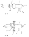
- the flame hydrolysis burner 11 'shown in FIG. 2 differs from the flame hydrolysis burner 11 shown in FIG. 1 in that it is designed as a double burner, the two burner heads 28 being arranged one above the other, as shown. However, it is also possible to arrange the two burning heads 28 side by side.
- the flame hydrolysis burner 11 "shown in FIG. 3 differs from the flame hydrolysis burner 11 according to FIG. 1 in that it has a nozzle opening 29 which has a plurality of outlet nozzle openings 30.
- the nozzle openings 30 or the number of nozzle openings 30 can be changed by means of the closure body 31 .
Landscapes
- Chemical & Material Sciences (AREA)
- Health & Medical Sciences (AREA)
- Engineering & Computer Science (AREA)
- Oral & Maxillofacial Surgery (AREA)
- Epidemiology (AREA)
- Chemical Kinetics & Catalysis (AREA)
- Materials Engineering (AREA)
- Mechanical Engineering (AREA)
- Metallurgy (AREA)
- Organic Chemistry (AREA)
- Veterinary Medicine (AREA)
- Public Health (AREA)
- General Health & Medical Sciences (AREA)
- Dentistry (AREA)
- General Chemical & Material Sciences (AREA)
- Life Sciences & Earth Sciences (AREA)
- Animal Behavior & Ethology (AREA)
- Physics & Mathematics (AREA)
- Plasma & Fusion (AREA)
- Inorganic Chemistry (AREA)
- Dental Preparations (AREA)
- Silicon Compounds (AREA)
- Dental Prosthetics (AREA)
- Materials For Medical Uses (AREA)
- Application Of Or Painting With Fluid Materials (AREA)
- Dental Tools And Instruments Or Auxiliary Dental Instruments (AREA)
Priority Applications (1)
| Application Number | Priority Date | Filing Date | Title |
|---|---|---|---|
| AT84113227T ATE55418T1 (de) | 1984-02-04 | 1984-11-02 | Vorrichtung zum beschichten eines metallischen dental-prothesenteils u.verfahren zum verbinden eines metallischen dentalprothesenteils mit dentalkunststoff. |
Applications Claiming Priority (2)
| Application Number | Priority Date | Filing Date | Title |
|---|---|---|---|
| DE3403894A DE3403894C1 (de) | 1984-02-04 | 1984-02-04 | Vorrichtung zum Beschichten eines metallischen Dentalprothesenteils und Verfahren zum Betrieb einer solchen Vorrichtung |
| DE3403894 | 1984-02-04 |
Publications (3)
| Publication Number | Publication Date |
|---|---|
| EP0151233A2 true EP0151233A2 (fr) | 1985-08-14 |
| EP0151233A3 EP0151233A3 (en) | 1988-03-23 |
| EP0151233B1 EP0151233B1 (fr) | 1990-08-08 |
Family
ID=6226762
Family Applications (1)
| Application Number | Title | Priority Date | Filing Date |
|---|---|---|---|
| EP84113227A Expired - Lifetime EP0151233B1 (fr) | 1984-02-04 | 1984-11-02 | Dispositif pour le revêtement d'une pièce de prothèse dentaire métallique et procédé pour la liaison d'une pièce de prothèse dentaire métallique avec une matière synthétique dentaire |
Country Status (11)
| Country | Link |
|---|---|
| US (1) | US4600390A (fr) |
| EP (1) | EP0151233B1 (fr) |
| JP (1) | JPS60185545A (fr) |
| AT (1) | ATE55418T1 (fr) |
| AU (1) | AU571643B2 (fr) |
| BR (1) | BR8500471A (fr) |
| CA (1) | CA1225547A (fr) |
| DD (1) | DD232429B1 (fr) |
| DE (2) | DE3403894C1 (fr) |
| HU (1) | HU194730B (fr) |
| YU (1) | YU14585A (fr) |
Cited By (12)
| Publication number | Priority date | Publication date | Assignee | Title |
|---|---|---|---|---|
| EP0170761B1 (fr) * | 1984-06-27 | 1988-04-20 | Kulzer & Co. GmbH | Disposition de traitement pour dispositif de revêtement par hydrolyse à la flamme |
| WO1988003405A3 (fr) * | 1986-11-06 | 1988-06-30 | Schuetz Dental Gmbh | Element de liaison prothetique partiel en metal |
| EP0298190A1 (fr) * | 1987-06-09 | 1989-01-11 | Heraeus Kulzer GmbH | Matériau dentaire composite et procédé de fabrication de tels matériaux |
| GR880100150A (en) * | 1987-03-13 | 1989-01-31 | Johnson & Johnson Dental Prod | Gluey coating for aluminium objects |
| FR2640495A1 (fr) * | 1988-12-16 | 1990-06-22 | Lyon Ecole Centrale | Nouvelle prothese dentaire fixee et procede de realisation |
| EP0365744A3 (fr) * | 1988-10-26 | 1991-04-03 | Heraeus Kulzer GmbH | Matériau composite métal/résine synthétique et procédé pour sa préparation |
| FR2692474A1 (fr) * | 1992-06-23 | 1993-12-24 | Plasma Technik Sa | Nouvelle prothèse plurale fixe et procédé de réalisation. |
| EP0580944A1 (fr) * | 1992-07-30 | 1994-02-02 | Heraeus Kulzer Gmbh | Procédé et dispositif pour la fabrication d'un composite métal-plastique |
| WO2006048276A1 (fr) * | 2004-11-03 | 2006-05-11 | Schott Ag | Objet presentant un revetement barriere et procede pour produire un tel objet |
| WO2006122744A1 (fr) * | 2005-05-19 | 2006-11-23 | Rehau Ag + Co | Procede de modification d'une surface en caoutchouc de silicone |
| DE102004029911B4 (de) * | 2003-06-20 | 2006-11-23 | Innovent E.V. Technologieentwicklung | Verfahren und Anordnung zur Herstellung anorganischer Schichten |
| EP1961835A1 (fr) * | 2007-02-20 | 2008-08-27 | W & H Dentalwerk Bürmoos GmbH | Procédé pour l'obtention d'un outil diamanté, en particulier pour la découpe de matériaux à base de pierre et similaires |
Families Citing this family (43)
| Publication number | Priority date | Publication date | Assignee | Title |
|---|---|---|---|---|
| US4681538A (en) * | 1984-04-23 | 1987-07-21 | Johnson & Johnson Dental Products, Company | Crystalline alumina composites |
| US4826430A (en) * | 1984-04-23 | 1989-05-02 | Johnson & Johnson Consumer Products, Inc. | Adhesive primer for alumina brackets |
| DE3642290C1 (de) * | 1986-12-11 | 1987-07-02 | Dentaire Ivoclar Ets | Verfahren zur Verbesserung der Haftung von Kunststoffen auf Metallen |
| DE3802042A1 (de) * | 1988-01-25 | 1989-07-27 | Thera Ges Fuer Patente | Verfahren zur vorbereitung einer substratoberflaeche fuer die verbindung mit kunststoff durch aufbringen einer siliciumhaltigen schicht und verwendung von siliciumhaltigem material |
| JPH07119570B2 (ja) * | 1988-05-27 | 1995-12-20 | 株式会社ニコン | アライメント方法 |
| US5190795A (en) * | 1989-09-14 | 1993-03-02 | Minnesota Mining And Manufacturing Company | Method for improving adhesion to metal |
| US5011410A (en) * | 1989-09-14 | 1991-04-30 | Minnesota Mining And Manufacturing Co. | Silane-treated metal dental articles |
| DE3933803A1 (de) * | 1989-10-10 | 1991-04-18 | Achim Ehlers | Retentionen zum anbringen von kunststoffverbindungen auf grundrohlingen sowie verfahren zum befestigen der retentionen auf diesen, insbesondere zu reparaturzwecken |
| US5234339A (en) * | 1991-02-14 | 1993-08-10 | Kulzer, Inc. | Implant supported prosthesis |
| US5356433A (en) * | 1991-08-13 | 1994-10-18 | Cordis Corporation | Biocompatible metal surfaces |
| DE4228530A1 (de) * | 1991-12-09 | 1993-06-17 | Roland Dr Goebel | Haftfeste, wasserundurchlaessige und hydrolysebestaendige verbundschicht fuer metall-, keramik-, glas-, polymer-kunststoff-verbunde und dispersion zu deren herstellung |
| ATE136452T1 (de) * | 1991-12-09 | 1996-04-15 | Heraeus Kulzer Gmbh | Haftfeste, wasserundurchlässige und hydrolysebeständige verbundschicht für metall-, keramik-, glas-, polymer-kunststoff-verbunde und dispersion zu deren herstellung |
| DE4237921A1 (de) * | 1992-10-23 | 1994-04-28 | Flachglas Ag | Verfahren und Vorrichtung zum Modifizieren der Oberflächenaktivität eines Silikatglassubstrates |
| DE4441123C1 (de) * | 1994-11-18 | 1995-11-09 | Heraeus Kulzer Gmbh | Gerät zur Behandlung von Dentalprothesenteilen |
| US5607475A (en) * | 1995-08-22 | 1997-03-04 | Medtronic, Inc. | Biocompatible medical article and method |
| DE19637513C2 (de) * | 1996-09-13 | 2001-06-07 | Fraunhofer Ges Forschung | Verfahren und Vorrichtung zur Modifizierung von metallischen Werkstückoberflächen durch elektrische Entladungen |
| US5904958A (en) * | 1998-03-20 | 1999-05-18 | Rexam Industries Corp. | Adjustable nozzle for evaporation or organic monomers |
| DE10019926A1 (de) | 2000-04-20 | 2001-10-31 | Isimat Gmbh Siebdruckmaschinen | Verfahren zum Modifizieren einer Oberfläche eines kompakten Substrates |
| DE10103586A1 (de) * | 2001-01-26 | 2002-08-01 | Roland Goebel | Primer zur Bildung einer haftfesten und feuchtestabilen Legierungs-Kunststoff-Verbundschicht und Verfahren zu seiner Herstellung |
| FR2820805A1 (fr) | 2001-02-12 | 2002-08-16 | Cebal | Tubes souples a proprietes barrieres ameliorees sans l'aide de vernis |
| US7387816B2 (en) * | 2003-12-15 | 2008-06-17 | Guardian Industries Corp. | Scratch resistant coated glass article including layer(s) resistant to fluoride-based etchant(s), and method of making article using combustion CVD |
| DE102004016436B3 (de) * | 2004-03-31 | 2005-12-29 | Verein zur Förderung von Innovationen durch Forschung, Entwicklung und Technologietransfer e.V. (Verein INNOVENT e.V.) | Verfahren zur Herstellung von Mehrschichtsystemen mit photokatalytischen Eigenschaften auf Oberflächen und dessen Verwendung |
| US7455883B2 (en) * | 2004-10-19 | 2008-11-25 | Guardian Industries Corp. | Hydrophilic DLC on substrate with flame pyrolysis treatment |
| US20060110605A1 (en) * | 2004-11-24 | 2006-05-25 | Guardian Industries Corp. | Hydrophilic coating and method of making same |
| US8088440B2 (en) * | 2004-11-24 | 2012-01-03 | Guardian Industries Corp. | Hydrophobic coating including underlayer(s) deposited via flame pyrolysis |
| US20060107599A1 (en) * | 2004-11-24 | 2006-05-25 | Guardian Industries Corp. | Flush-mounted slider window for pick-up truck with hydrophilic coating on interior surface thereof, and method of making same |
| US7597938B2 (en) * | 2004-11-29 | 2009-10-06 | Guardian Industries Corp. | Method of making coated article with color suppression coating including flame pyrolysis deposited layer(s) |
| DE102005005334A1 (de) * | 2005-01-28 | 2006-08-10 | Blanco Gmbh + Co Kg | Beschichtetes Metall-Substrat |
| US20060246218A1 (en) * | 2005-04-29 | 2006-11-02 | Guardian Industries Corp. | Hydrophilic DLC on substrate with barrier discharge pyrolysis treatment |
| DE102006045617B4 (de) | 2006-09-22 | 2010-06-10 | Innovent E.V. Technologieentwicklung | Verfahren zur Herstellung einer anorganisch-anorganischen Gradientenverbundschicht |
| DE102007045455A1 (de) | 2007-09-24 | 2009-04-09 | Schott Ag | Verfahren zur Herstellung von Wafern aus Ingots |
| US8347814B2 (en) * | 2008-01-22 | 2013-01-08 | Raytheon Canada Limited | Method and apparatus for coating a curved surface |
| US20090258151A1 (en) * | 2008-04-10 | 2009-10-15 | Raytheon Company | Method and Apparatus for Coating Curved Surfaces |
| US8398776B2 (en) * | 2008-05-12 | 2013-03-19 | Raytheon Canada Limited | Method and apparatus for supporting workpieces in a coating apparatus |
| US8246748B2 (en) * | 2008-07-09 | 2012-08-21 | Raytheon Canada Limited | Method and apparatus for coating surfaces |
| US8003164B2 (en) * | 2008-09-19 | 2011-08-23 | Guardian Industries Corp. | Method of making a scratch-and etch-resistant coated glass article |
| DE102008060923B4 (de) | 2008-12-06 | 2012-09-27 | Innovent E.V. | Verwendung einer Schicht |
| US10006627B2 (en) * | 2008-12-23 | 2018-06-26 | Stephen William John Grant | Dual fuel boiler |
| DE102009031305A1 (de) | 2009-06-30 | 2011-01-05 | Uhde Gmbh | Katalysatorbeschichteter Träger, Verfahren zu dessen Herstellung, ein damit ausgestatteter Reaktor und dessen Verwendung |
| US20110020623A1 (en) * | 2009-07-22 | 2011-01-27 | Raytheon Company | Method and Apparatus for Repairing an Optical Component Substrate Through Coating |
| DE102009051593B4 (de) | 2009-11-02 | 2018-05-09 | Xplus3 Gmbh | Verfahren zur Herstellung eines Werkstoffverbundes zwischen einer Oxidkeramik und einem auf diese aufzubringenden Verblendwerkstoff, Verwendung des Werkstoffverbundes sowie Kit für den Haftvermittler |
| US11213848B2 (en) * | 2015-12-11 | 2022-01-04 | Vitro Flat Glass Llc | Nanoparticle coater |
| DE102016009188A1 (de) | 2016-07-26 | 2018-02-01 | Martin Heimann | Optimierung des Verbundes zwischen Oxidkeramik und einem Verblendwerkstoff für dentale Zwecke durch Zusatz eines auf den Verblendwerkstoff abgestimmten Bonders und seine Applikation |
Family Cites Families (9)
| Publication number | Priority date | Publication date | Assignee | Title |
|---|---|---|---|---|
| DE1671240A1 (de) * | 1968-02-26 | 1971-08-26 | Elektronische Bauelemente Veb | Verfahren zur Herstellung von insbesondere gleichstrombestaendigen,keramischen Traegerkoerpern fuer Schichtwiderstaende |
| US3565346A (en) * | 1968-07-11 | 1971-02-23 | Texas Instruments Inc | Method and apparatus for forming an article of high purity metal oxide |
| US3806570A (en) * | 1972-03-30 | 1974-04-23 | Corning Glass Works | Method for producing high quality fused silica |
| US3873339A (en) * | 1972-03-30 | 1975-03-25 | Corning Glass Works | Method of forming optical waveguide circuit path |
| FR2291736A1 (fr) * | 1974-11-21 | 1976-06-18 | Europ Composants Electron | Article de prothese et son procede de fabrication |
| US3966446A (en) * | 1975-10-23 | 1976-06-29 | Bell Telephone Laboratories, Incorporated | Axial fabrication of optical fibers |
| US4212663A (en) * | 1978-01-26 | 1980-07-15 | Corning Glass Works | Reactants delivery system for optical waveguide manufacturing |
| DE2849240C2 (de) * | 1978-11-13 | 1983-01-13 | Siemens Ag, 1000 Berlin Und 8000 Muenchen | CVD-Beschichtungsvorrichtung für Kleinteile und ihre Verwendung |
| US4364731A (en) * | 1981-01-29 | 1982-12-21 | Board Of Regents, The University Of Texas System | Methods for producing adhesive bonds between substrate and polymer employing an intermediate oxide layer |
-
1984
- 1984-02-04 DE DE3403894A patent/DE3403894C1/de not_active Expired
- 1984-11-02 AT AT84113227T patent/ATE55418T1/de not_active IP Right Cessation
- 1984-11-02 DE DE8484113227T patent/DE3482954D1/de not_active Expired - Fee Related
- 1984-11-02 EP EP84113227A patent/EP0151233B1/fr not_active Expired - Lifetime
- 1984-12-11 DD DD84270581A patent/DD232429B1/de not_active IP Right Cessation
- 1984-12-26 US US06/686,211 patent/US4600390A/en not_active Expired - Lifetime
-
1985
- 1985-01-30 JP JP60014615A patent/JPS60185545A/ja active Granted
- 1985-01-31 HU HU85372A patent/HU194730B/hu unknown
- 1985-01-31 YU YU00145/85A patent/YU14585A/xx unknown
- 1985-02-01 AU AU38294/85A patent/AU571643B2/en not_active Ceased
- 1985-02-01 CA CA000473421A patent/CA1225547A/fr not_active Expired
- 1985-02-01 BR BR8500471A patent/BR8500471A/pt not_active IP Right Cessation
Cited By (14)
| Publication number | Priority date | Publication date | Assignee | Title |
|---|---|---|---|---|
| EP0170761B1 (fr) * | 1984-06-27 | 1988-04-20 | Kulzer & Co. GmbH | Disposition de traitement pour dispositif de revêtement par hydrolyse à la flamme |
| WO1988003405A3 (fr) * | 1986-11-06 | 1988-06-30 | Schuetz Dental Gmbh | Element de liaison prothetique partiel en metal |
| GR880100150A (en) * | 1987-03-13 | 1989-01-31 | Johnson & Johnson Dental Prod | Gluey coating for aluminium objects |
| EP0282325A3 (en) * | 1987-03-13 | 1990-03-07 | Johnson & Johnson Dental Products Company | Adhesive primer for alumina articles |
| EP0298190A1 (fr) * | 1987-06-09 | 1989-01-11 | Heraeus Kulzer GmbH | Matériau dentaire composite et procédé de fabrication de tels matériaux |
| EP0365744A3 (fr) * | 1988-10-26 | 1991-04-03 | Heraeus Kulzer GmbH | Matériau composite métal/résine synthétique et procédé pour sa préparation |
| WO1990006733A1 (fr) * | 1988-12-16 | 1990-06-28 | Ecole Centrale De Lyon | Nouvelle prothese dentaire fixee et procede de realisation |
| FR2640495A1 (fr) * | 1988-12-16 | 1990-06-22 | Lyon Ecole Centrale | Nouvelle prothese dentaire fixee et procede de realisation |
| FR2692474A1 (fr) * | 1992-06-23 | 1993-12-24 | Plasma Technik Sa | Nouvelle prothèse plurale fixe et procédé de réalisation. |
| EP0580944A1 (fr) * | 1992-07-30 | 1994-02-02 | Heraeus Kulzer Gmbh | Procédé et dispositif pour la fabrication d'un composite métal-plastique |
| DE102004029911B4 (de) * | 2003-06-20 | 2006-11-23 | Innovent E.V. Technologieentwicklung | Verfahren und Anordnung zur Herstellung anorganischer Schichten |
| WO2006048276A1 (fr) * | 2004-11-03 | 2006-05-11 | Schott Ag | Objet presentant un revetement barriere et procede pour produire un tel objet |
| WO2006122744A1 (fr) * | 2005-05-19 | 2006-11-23 | Rehau Ag + Co | Procede de modification d'une surface en caoutchouc de silicone |
| EP1961835A1 (fr) * | 2007-02-20 | 2008-08-27 | W & H Dentalwerk Bürmoos GmbH | Procédé pour l'obtention d'un outil diamanté, en particulier pour la découpe de matériaux à base de pierre et similaires |
Also Published As
| Publication number | Publication date |
|---|---|
| AU3829485A (en) | 1985-08-08 |
| US4600390A (en) | 1986-07-15 |
| EP0151233B1 (fr) | 1990-08-08 |
| AU571643B2 (en) | 1988-04-21 |
| HU194730B (en) | 1988-03-28 |
| JPS60185545A (ja) | 1985-09-21 |
| HUT38526A (en) | 1986-06-30 |
| YU14585A (en) | 1988-04-30 |
| JPH0376142B2 (fr) | 1991-12-04 |
| DD232429A1 (de) | 1986-01-29 |
| BR8500471A (pt) | 1985-09-17 |
| ATE55418T1 (de) | 1990-08-15 |
| DE3403894C1 (de) | 1985-07-25 |
| DD232429B1 (de) | 1988-09-14 |
| CA1225547A (fr) | 1987-08-18 |
| EP0151233A3 (en) | 1988-03-23 |
| DE3482954D1 (de) | 1990-09-13 |
Similar Documents
| Publication | Publication Date | Title |
|---|---|---|
| EP0151233B1 (fr) | Dispositif pour le revêtement d'une pièce de prothèse dentaire métallique et procédé pour la liaison d'une pièce de prothèse dentaire métallique avec une matière synthétique dentaire | |
| DE69123152T2 (de) | Hochgeschwindigkeitslichtbogenspritzvorrichtung und verfahren zum formen von material | |
| DE10239875B4 (de) | Verfahren und Vorrichtung zur großflächigen Beschichtung von Substraten bei Atmosphärendruckbedingungen | |
| DD259586A5 (de) | Verfahren zur herstellung von gespruehten abreibbaren beschichtungen und nach dem verfahren hergestellte beschichtung | |
| DE3884697T2 (de) | Verfahren zur gesteigerten Abscheidung von Siliciumoxid durch Plasma. | |
| DE3879445T2 (de) | Apparat und verfahren zum erzeugen einer beschichtung von hoher dichte durch thermische zerstaeubung. | |
| DE69125118T2 (de) | Verfahren zur Herstellung eines Diamant-Überzuges | |
| DE2452684C2 (de) | Verfahren und Vorrichtung zur gleichmäßigen Verteilung eines Stromes zerstäubter Teilchen auf einem Substrat | |
| EP2737101B1 (fr) | Procédé de revêtement mettant en oeuvre des matériaux de revêtement pulvérulents spéciaux et utilisation de tels matériaux de revêtement | |
| DE3942050A1 (de) | Verfahren und vorrichtung zur laserplasmaspritzung mit axialer stroemung | |
| DE10224780A1 (de) | Verfahren und Vorrichtung zum Kaltgasspritzen | |
| EP0124829A1 (fr) | Dispositif d'évaporation avec chauffage par faisceau pour le dépôt de plusieurs matériaux | |
| DE69511469T2 (de) | Verfahren und Vorrichtung zur Herstellung von Diamanten | |
| DE102004029911B4 (de) | Verfahren und Anordnung zur Herstellung anorganischer Schichten | |
| EP4045213B1 (fr) | Procédé et dispositif de production d'une poudre métallique | |
| DE10253794A1 (de) | Niedertemperatur Hochgeschwindigkeits-Flammspritzsystem | |
| DE102013200067A1 (de) | Vorrichtung zum thermischen Beschichten einer Oberfläche | |
| DE2127563A1 (en) | Metal flake or platelets - by fast cooling of metal spray | |
| EP0975821B1 (fr) | Reacteur de depot chimique en phase vapeur et son utilisation | |
| DE2161453C3 (de) | Verfahren zur Herstellung eines Reibhelages auf Unterlagen, wie Bremsen oder Kupplungen mittels Plasmastrahl | |
| DE2544847A1 (de) | Thermische pulverspritzvorrichtung | |
| EP4131332A1 (fr) | Cible de pulvérisations multiple | |
| DE10119288B4 (de) | Verfahren und Einrichtung zur gasdynamischen Beschichtung von Oberflächen mittels Schalldüsen | |
| DE4225352C1 (de) | Vorrichtung zum reaktiven Aufdampfen von Metallverbindungen und Verfahren | |
| DE4009351C2 (fr) |
Legal Events
| Date | Code | Title | Description |
|---|---|---|---|
| PUAI | Public reference made under article 153(3) epc to a published international application that has entered the european phase |
Free format text: ORIGINAL CODE: 0009012 |
|
| 17P | Request for examination filed |
Effective date: 19841109 |
|
| AK | Designated contracting states |
Kind code of ref document: A2 Designated state(s): AT CH DE FR GB IT LI SE Designated state(s): AT CH DE FR GB IT LI SE |
|
| ITCL | It: translation for ep claims filed |
Representative=s name: SOCIETA' ITALIANA BREVETTI S.P.A. |
|
| EL | Fr: translation of claims filed | ||
| PUAL | Search report despatched |
Free format text: ORIGINAL CODE: 0009013 |
|
| AK | Designated contracting states |
Kind code of ref document: A3 Designated state(s): AT CH DE FR GB IT LI SE |
|
| RAP1 | Party data changed (applicant data changed or rights of an application transferred) |
Owner name: KULZER GMBH |
|
| 17Q | First examination report despatched |
Effective date: 19890616 |
|
| GRAA | (expected) grant |
Free format text: ORIGINAL CODE: 0009210 |
|
| AK | Designated contracting states |
Kind code of ref document: B1 Designated state(s): AT CH DE FR GB IT LI SE |
|
| REF | Corresponds to: |
Ref document number: 55418 Country of ref document: AT Date of ref document: 19900815 Kind code of ref document: T |
|
| ET | Fr: translation filed | ||
| GBT | Gb: translation of ep patent filed (gb section 77(6)(a)/1977) | ||
| REF | Corresponds to: |
Ref document number: 3482954 Country of ref document: DE Date of ref document: 19900913 |
|
| ITF | It: translation for a ep patent filed | ||
| PLBE | No opposition filed within time limit |
Free format text: ORIGINAL CODE: 0009261 |
|
| STAA | Information on the status of an ep patent application or granted ep patent |
Free format text: STATUS: NO OPPOSITION FILED WITHIN TIME LIMIT |
|
| 26N | No opposition filed | ||
| ITTA | It: last paid annual fee | ||
| EAL | Se: european patent in force in sweden |
Ref document number: 84113227.7 |
|
| PGFP | Annual fee paid to national office [announced via postgrant information from national office to epo] |
Ref country code: GB Payment date: 19980910 Year of fee payment: 15 |
|
| PGFP | Annual fee paid to national office [announced via postgrant information from national office to epo] |
Ref country code: SE Payment date: 19981015 Year of fee payment: 15 |
|
| PGFP | Annual fee paid to national office [announced via postgrant information from national office to epo] |
Ref country code: DE Payment date: 19981103 Year of fee payment: 15 |
|
| PGFP | Annual fee paid to national office [announced via postgrant information from national office to epo] |
Ref country code: AT Payment date: 19981105 Year of fee payment: 15 |
|
| PGFP | Annual fee paid to national office [announced via postgrant information from national office to epo] |
Ref country code: FR Payment date: 19981130 Year of fee payment: 15 |
|
| PGFP | Annual fee paid to national office [announced via postgrant information from national office to epo] |
Ref country code: CH Payment date: 19990218 Year of fee payment: 15 |
|
| PG25 | Lapsed in a contracting state [announced via postgrant information from national office to epo] |
Ref country code: GB Free format text: LAPSE BECAUSE OF NON-PAYMENT OF DUE FEES Effective date: 19991102 Ref country code: AT Free format text: LAPSE BECAUSE OF NON-PAYMENT OF DUE FEES Effective date: 19991102 |
|
| PG25 | Lapsed in a contracting state [announced via postgrant information from national office to epo] |
Ref country code: SE Free format text: LAPSE BECAUSE OF NON-PAYMENT OF DUE FEES Effective date: 19991103 |
|
| PG25 | Lapsed in a contracting state [announced via postgrant information from national office to epo] |
Ref country code: LI Free format text: LAPSE BECAUSE OF NON-PAYMENT OF DUE FEES Effective date: 19991130 Ref country code: CH Free format text: LAPSE BECAUSE OF NON-PAYMENT OF DUE FEES Effective date: 19991130 |
|
| GBPC | Gb: european patent ceased through non-payment of renewal fee |
Effective date: 19991102 |
|
| REG | Reference to a national code |
Ref country code: CH Ref legal event code: PL |
|
| EUG | Se: european patent has lapsed |
Ref document number: 84113227.7 |
|
| PG25 | Lapsed in a contracting state [announced via postgrant information from national office to epo] |
Ref country code: FR Free format text: LAPSE BECAUSE OF NON-PAYMENT OF DUE FEES Effective date: 20000731 |
|
| PG25 | Lapsed in a contracting state [announced via postgrant information from national office to epo] |
Ref country code: DE Free format text: LAPSE BECAUSE OF NON-PAYMENT OF DUE FEES Effective date: 20000901 |
|
| REG | Reference to a national code |
Ref country code: FR Ref legal event code: ST |