EP0151285A2 - Système de montage pour une sonde longiligne - Google Patents
Système de montage pour une sonde longiligne Download PDFInfo
- Publication number
- EP0151285A2 EP0151285A2 EP84115580A EP84115580A EP0151285A2 EP 0151285 A2 EP0151285 A2 EP 0151285A2 EP 84115580 A EP84115580 A EP 84115580A EP 84115580 A EP84115580 A EP 84115580A EP 0151285 A2 EP0151285 A2 EP 0151285A2
- Authority
- EP
- European Patent Office
- Prior art keywords
- closure piece
- guide tube
- opening
- probe
- shaped
- Prior art date
- Legal status (The legal status is an assumption and is not a legal conclusion. Google has not performed a legal analysis and makes no representation as to the accuracy of the status listed.)
- Ceased
Links
- 239000000523 sample Substances 0.000 title claims abstract description 28
- 238000007654 immersion Methods 0.000 claims abstract description 4
- 238000009434 installation Methods 0.000 claims description 4
- 238000007789 sealing Methods 0.000 claims description 4
- 238000012423 maintenance Methods 0.000 abstract description 3
- 239000000565 sealant Substances 0.000 description 2
- 238000010276 construction Methods 0.000 description 1
- 238000004519 manufacturing process Methods 0.000 description 1
- 239000000126 substance Substances 0.000 description 1
Images

Classifications
-
- G—PHYSICS
- G01—MEASURING; TESTING
- G01K—MEASURING TEMPERATURE; MEASURING QUANTITY OF HEAT; THERMALLY-SENSITIVE ELEMENTS NOT OTHERWISE PROVIDED FOR
- G01K1/00—Details of thermometers not specially adapted for particular types of thermometer
- G01K1/14—Supports; Fastening devices; Arrangements for mounting thermometers in particular locations
- G01K1/146—Supports; Fastening devices; Arrangements for mounting thermometers in particular locations arrangements for moving thermometers to or from a measuring position
-
- G—PHYSICS
- G01—MEASURING; TESTING
- G01N—INVESTIGATING OR ANALYSING MATERIALS BY DETERMINING THEIR CHEMICAL OR PHYSICAL PROPERTIES
- G01N27/00—Investigating or analysing materials by the use of electric, electrochemical, or magnetic means
- G01N27/02—Investigating or analysing materials by the use of electric, electrochemical, or magnetic means by investigating impedance
- G01N27/04—Investigating or analysing materials by the use of electric, electrochemical, or magnetic means by investigating impedance by investigating resistance
- G01N27/06—Investigating or analysing materials by the use of electric, electrochemical, or magnetic means by investigating impedance by investigating resistance of a liquid
- G01N27/07—Construction of measuring vessels; Electrodes therefor
-
- G—PHYSICS
- G01—MEASURING; TESTING
- G01N—INVESTIGATING OR ANALYSING MATERIALS BY DETERMINING THEIR CHEMICAL OR PHYSICAL PROPERTIES
- G01N27/00—Investigating or analysing materials by the use of electric, electrochemical, or magnetic means
- G01N27/26—Investigating or analysing materials by the use of electric, electrochemical, or magnetic means by investigating electrochemical variables; by using electrolysis or electrophoresis
- G01N27/28—Electrolytic cell components
- G01N27/283—Means for supporting or introducing electrochemical probes
Definitions
- the invention relates to a built-in fitting for rod-shaped probes, in particular a transducer designed as an immersion sensor, with a guide tube for the probe attached to an opening in a container wall and composed of sections, and with means inserted between the sections for closing the guide tube.
- Installation fittings of this type are used to close the guide tube and thus the opening in the container wall when the probe is removed for maintenance or replacement purposes.
- a rotary valve is provided as a closure means with a bore running transversely to the axis of rotation in the spherical or conical valve body, through which the shaft of the tubular probe is guided in the working position.
- the valve can be closed while the probe is tightly guided in the guide tube, so that the substance in the container is prevented from escaping.
- a disadvantage of such a fitting is the length caused by the installation of the valve housing of the rotary valve, which in turn requires probes with relatively long rod-shaped shafts.
- Another disadvantage is the relatively complex mechanical structure, in which even if the pipe sections and the rotary valve are carefully aligned, the joints in the guide tube which result in damage to the rod-shaped probe if it is not inserted properly or its sealing means, such as O-rings or the like, attached to the probe shaft can.
- a sealant is arranged between the rod-shaped probe and the guide tube above the rotary slide plane, there is no need to drive over any joints that could damage the sealant, for example an O-ring.
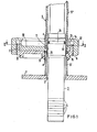
- FIGS. 1 and 2 Further advantages and features result from the description of an exemplary embodiment shown in FIGS. 1 and 2.
- Figure 1 In the container wall 1 of a container surrounding the medium or a line there is an opening 2 for introducing a rod-shaped probe 3 or an immersion sensor.
- a rod-shaped probe 3 or an immersion sensor In the example shown, it is a known conductivity sensor with four ring-shaped stray field electrodes 4.
- a cylindrical tube piece is welded coaxially to the opening 2 and with the same inner diameter, which forms the first tube section 5 'of a guide tube 5 in the fitting for the rod-shaped probe 3.
- closure piece 6 in the form of a circular disk with a cylindrically raised edge 7 which is provided with thread 8 on its outer surface.
- the closure piece 6 also has an eccentrically mounted axially outside its central axis a - a ' circular opening 9, which is coaxially connected to the attached to the container wall 1 first tube section 5 'of the guide tube 5.
- a disk-shaped rotary slide valve 10 with a sliding fit is fitted coaxially to the central axis a - a ', which can be rotated about the central axis a - a' and whose cylindrical outer surface rests on the inner surface of the raised edge 7 of the closure piece 6 as a guide surface.
- a circular opening 11 is eccentrically arranged such that it is aligned with an opening 9 in the closure piece 10 in a slide valve position, as shown in the figure.
- the opening 11 is connected to a further section 5 ′′ of the guide tube 5.
- a union nut 12 can be screwed onto the thread 8 of the closure piece 6, the radially inwardly drawn edge 13 of which rests coherently on the end face 14 of the rotary valve 10.
- the rotary valve 10 has - as can be seen from the figure - no physical axis or shaft and is therefore easy to manufacture.
- An O-ring 15 serves as an elastic sealing means between the closure piece 6 and the rotary slide valve 10, which is fitted in an annular groove 16 surrounding the opening 9, the walls of which are formed from horizontal and vertical partial surfaces of the closure piece 6 and the rotary slide valve 10.
- Another O-ring 17 is arranged with a circumferential groove 18 in the shaft of the probe 3 and serves to seal between the rod-shaped probe 3 and the inner wall of the guide tube 5, here the tube section 5 ".
- the O-ring 17 lies in a plane above the rotary valve 10.
- FIG. 2 shows a section in the plane I - II through the installation fitting according to FIG. 1.
- probe 3 is not shown.
- the inner diameters of the guide tube sections and the openings in the rotary valve or in the closure piece are the same.
- an inwardly directed nose 19 can be provided.
- the guide tube 5 is dimensioned such that in this position the part of the shaft with the O-ring 17 is still inside the guide tube.
- the rotary valve 10 is then rotated in the locking piece 6 180 0, so that the opening 9 is closed in the closure member. 6
Landscapes
- Chemical & Material Sciences (AREA)
- Health & Medical Sciences (AREA)
- General Physics & Mathematics (AREA)
- Physics & Mathematics (AREA)
- Life Sciences & Earth Sciences (AREA)
- Biochemistry (AREA)
- Electrochemistry (AREA)
- Analytical Chemistry (AREA)
- Chemical Kinetics & Catalysis (AREA)
- General Health & Medical Sciences (AREA)
- Immunology (AREA)
- Pathology (AREA)
- Molecular Biology (AREA)
- Investigating Or Analyzing Materials By The Use Of Magnetic Means (AREA)
- Investigating Or Analyzing Materials By The Use Of Ultrasonic Waves (AREA)
- Monitoring And Testing Of Nuclear Reactors (AREA)
- Sampling And Sample Adjustment (AREA)
- Closures For Containers (AREA)
Applications Claiming Priority (2)
| Application Number | Priority Date | Filing Date | Title |
|---|---|---|---|
| DE19843404639 DE3404639A1 (de) | 1984-02-09 | 1984-02-09 | Einbauarmatur fuer stabfoermige sonden |
| DE3404639 | 1984-02-09 |
Publications (2)
| Publication Number | Publication Date |
|---|---|
| EP0151285A2 true EP0151285A2 (fr) | 1985-08-14 |
| EP0151285A3 EP0151285A3 (fr) | 1987-05-06 |
Family
ID=6227268
Family Applications (1)
| Application Number | Title | Priority Date | Filing Date |
|---|---|---|---|
| EP84115580A Ceased EP0151285A3 (fr) | 1984-02-09 | 1984-12-17 | Système de montage pour une sonde longiligne |
Country Status (2)
| Country | Link |
|---|---|
| EP (1) | EP0151285A3 (fr) |
| DE (1) | DE3404639A1 (fr) |
Cited By (3)
| Publication number | Priority date | Publication date | Assignee | Title |
|---|---|---|---|---|
| EP0176906A3 (fr) * | 1984-09-27 | 1987-11-25 | GWF Gas- & Wassermesserfabrik AG | Dispositif pour effectuer des mesures dans un conduit tubulaire |
| US8123397B2 (en) * | 2006-01-11 | 2012-02-28 | Sartorius Stedim Biotech Gmbh | Disposable container having sensor mounts sealed to the container and sensors in the sensor mounts for measuring at least one parameter of media in the container |
| US12313586B2 (en) | 2017-09-22 | 2025-05-27 | Broadley-James Corporation | Sensing element for use with media-preserving storage and calibration chamber |
Families Citing this family (7)
| Publication number | Priority date | Publication date | Assignee | Title |
|---|---|---|---|---|
| DE3737914C2 (de) * | 1987-11-07 | 1994-12-01 | Messer Griesheim Gmbh | Anordnung eines Fühlers, insbsondere eines Temperaturfühlers, in einer Behälterwand oder dergleichen Wand |
| US6773678B2 (en) | 2000-03-20 | 2004-08-10 | Endress + Hauser Conducta Gesellschaft Fur Mess Und Regeltechnik Mbh + Co. | Mounting system and retractable sensor holder for analytical sensors |
| DE10054272A1 (de) * | 2000-11-02 | 2002-05-08 | Conducta Endress & Hauser | Wechselarmatur |
| DE10162715A1 (de) * | 2001-12-19 | 2003-07-10 | Gneuss Kunststofftechnik Gmbh | Halterung zur lösbaren Aufnahme von Sensoren |
| DE102006005533B4 (de) | 2006-02-07 | 2008-04-17 | Sartorius Stedim Biotech Gmbh | Verbindersystem und Verfahren zum sterilen Verbinden |
| DE102009052266B4 (de) | 2009-11-06 | 2015-05-28 | Eppendorf Ag | Sensoradapter, Herstellungsverfahren für den Sensoradapter, Verfahren zum Einsetzen eines Sensors in diesen Sensoradapter |
| CN106829245B (zh) * | 2017-01-05 | 2020-05-12 | 大唐彬长发电有限责任公司 | 一种带有料位计的电除尘灰斗装置 |
Family Cites Families (3)
| Publication number | Priority date | Publication date | Assignee | Title |
|---|---|---|---|---|
| US2870629A (en) * | 1956-01-18 | 1959-01-27 | Willis Oil Tool Co | Apparatus for moving an element into and from a vessel containing fluid under pressure |
| CH521657A (de) * | 1970-12-14 | 1972-04-15 | Proton Ag | Messwertgebereinrichtung mit herausnehmbarer Messwertgebersonde |
| US4215458A (en) * | 1979-02-09 | 1980-08-05 | Lancaster Robert D | Extractor tool |
-
1984
- 1984-02-09 DE DE19843404639 patent/DE3404639A1/de not_active Withdrawn
- 1984-12-17 EP EP84115580A patent/EP0151285A3/fr not_active Ceased
Cited By (3)
| Publication number | Priority date | Publication date | Assignee | Title |
|---|---|---|---|---|
| EP0176906A3 (fr) * | 1984-09-27 | 1987-11-25 | GWF Gas- & Wassermesserfabrik AG | Dispositif pour effectuer des mesures dans un conduit tubulaire |
| US8123397B2 (en) * | 2006-01-11 | 2012-02-28 | Sartorius Stedim Biotech Gmbh | Disposable container having sensor mounts sealed to the container and sensors in the sensor mounts for measuring at least one parameter of media in the container |
| US12313586B2 (en) | 2017-09-22 | 2025-05-27 | Broadley-James Corporation | Sensing element for use with media-preserving storage and calibration chamber |
Also Published As
| Publication number | Publication date |
|---|---|
| DE3404639A1 (de) | 1985-08-14 |
| EP0151285A3 (fr) | 1987-05-06 |
Similar Documents
| Publication | Publication Date | Title |
|---|---|---|
| CH112451A (de) | Drosselklappenventil. | |
| DE1650419A1 (de) | Durchgangsventil fuer fluessige oder fliessfaehige Medien | |
| EP0151285A2 (fr) | Système de montage pour une sonde longiligne | |
| EP0061415A1 (fr) | Soupape pour systèmes hydrauliques | |
| CH640036A5 (de) | Ventil mit einstellbarem durchflussquerschnitt sowie verwendung desselben. | |
| DE102016114565A1 (de) | Messanordnung | |
| DE69125628T2 (de) | Gerät zur messung und steuerung von temperatur und/oder druck | |
| CH662404A5 (de) | Vorrichtung zum ermitteln von messgroessen in rohrleitungssystemen. | |
| DE69202375T2 (de) | Hydraulischer Zylinder mit Vorrichtung zum Anzeigen der Kolbenstellung. | |
| DE19738427B4 (de) | Vorrichtung zum automatischen Blockieren eines Kraftfahrzeugrades auf einer Welle einer Auswuchtmaschine | |
| EP0884506B1 (fr) | Raccorderie, notamment clapet de réglage et d'arrêt | |
| DE3811937C2 (de) | Scheibenventil | |
| DE3719763A1 (de) | Anschlaganordnung fuer ein ventil | |
| CH313441A (de) | Absperrorgan | |
| DE7540606U (de) | Drehventil | |
| CH394743A (de) | Absperrhahn mit kugelingem Küken | |
| DE3508246C1 (de) | Druckmeßgerät | |
| EP1030289A2 (fr) | Dispositif de support pour un capteur | |
| DE3030086A1 (de) | Auswechselbare elektrodenanordnung fuer magnetische durchflussmesser | |
| DE3616964C2 (de) | Anschlußverbindungsstück | |
| DE724308C (de) | Absperrhahn | |
| EP0417706A2 (fr) | Robinet d'arrêt | |
| EP3059478B1 (fr) | Dispositif destine a afficher et/ou a reguler des fluides | |
| DE2754780A1 (de) | Ventilgehaeuse mit entfernbarer, in sich geschlossener ventileinheit | |
| EP0866256A2 (fr) | Accouplement de serrage |
Legal Events
| Date | Code | Title | Description |
|---|---|---|---|
| PUAI | Public reference made under article 153(3) epc to a published international application that has entered the european phase |
Free format text: ORIGINAL CODE: 0009012 |
|
| AK | Designated contracting states |
Designated state(s): AT BE DE FR GB IT NL SE |
|
| PUAL | Search report despatched |
Free format text: ORIGINAL CODE: 0009013 |
|
| AK | Designated contracting states |
Kind code of ref document: A3 Designated state(s): AT BE DE FR GB IT NL SE |
|
| 17P | Request for examination filed |
Effective date: 19871030 |
|
| 17Q | First examination report despatched |
Effective date: 19880210 |
|
| STAA | Information on the status of an ep patent application or granted ep patent |
Free format text: STATUS: THE APPLICATION HAS BEEN REFUSED |
|
| 18R | Application refused |
Effective date: 19880804 |
|
| RIN1 | Information on inventor provided before grant (corrected) |
Inventor name: THIEME, ROLAND |