EP0151331A1 - Appareil de projection d'image - Google Patents
Appareil de projection d'image Download PDFInfo
- Publication number
- EP0151331A1 EP0151331A1 EP84300211A EP84300211A EP0151331A1 EP 0151331 A1 EP0151331 A1 EP 0151331A1 EP 84300211 A EP84300211 A EP 84300211A EP 84300211 A EP84300211 A EP 84300211A EP 0151331 A1 EP0151331 A1 EP 0151331A1
- Authority
- EP
- European Patent Office
- Prior art keywords
- image
- light
- images
- shield plate
- stripes
- Prior art date
- Legal status (The legal status is an assumption and is not a legal conclusion. Google has not performed a legal analysis and makes no representation as to the accuracy of the status listed.)
- Granted
Links
- 238000009792 diffusion process Methods 0.000 claims abstract description 47
- OAICVXFJPJFONN-UHFFFAOYSA-N Phosphorus Chemical compound [P] OAICVXFJPJFONN-UHFFFAOYSA-N 0.000 claims abstract description 34
- 239000003086 colorant Substances 0.000 claims abstract description 16
- 239000000758 substrate Substances 0.000 claims description 16
- 230000003252 repetitive effect Effects 0.000 claims description 2
- 230000000007 visual effect Effects 0.000 claims 2
- 239000011159 matrix material Substances 0.000 claims 1
- 230000003287 optical effect Effects 0.000 description 6
- 238000010276 construction Methods 0.000 description 5
- 238000010894 electron beam technology Methods 0.000 description 4
- 230000004048 modification Effects 0.000 description 4
- 238000012986 modification Methods 0.000 description 4
- 230000005540 biological transmission Effects 0.000 description 2
- 238000006073 displacement reaction Methods 0.000 description 2
- 238000000034 method Methods 0.000 description 2
- 230000002093 peripheral effect Effects 0.000 description 2
- 230000010287 polarization Effects 0.000 description 2
- OKTJSMMVPCPJKN-UHFFFAOYSA-N Carbon Chemical compound [C] OKTJSMMVPCPJKN-UHFFFAOYSA-N 0.000 description 1
- 239000011358 absorbing material Substances 0.000 description 1
- 208000003464 asthenopia Diseases 0.000 description 1
- 229910052799 carbon Inorganic materials 0.000 description 1
- 230000003247 decreasing effect Effects 0.000 description 1
- 230000000694 effects Effects 0.000 description 1
- 230000005284 excitation Effects 0.000 description 1
- 239000011521 glass Substances 0.000 description 1
- 210000003128 head Anatomy 0.000 description 1
- 238000005286 illumination Methods 0.000 description 1
- 239000000463 material Substances 0.000 description 1
- 229920003217 poly(methylsilsesquioxane) Polymers 0.000 description 1
- 230000005855 radiation Effects 0.000 description 1
- 229920003002 synthetic resin Polymers 0.000 description 1
- 239000000057 synthetic resin Substances 0.000 description 1
Images



Classifications
-
- H—ELECTRICITY
- H04—ELECTRIC COMMUNICATION TECHNIQUE
- H04N—PICTORIAL COMMUNICATION, e.g. TELEVISION
- H04N9/00—Details of colour television systems
- H04N9/12—Picture reproducers
- H04N9/31—Projection devices for colour picture display, e.g. using electronic spatial light modulators [ESLM]
-
- H—ELECTRICITY
- H04—ELECTRIC COMMUNICATION TECHNIQUE
- H04N—PICTORIAL COMMUNICATION, e.g. TELEVISION
- H04N13/00—Stereoscopic video systems; Multi-view video systems; Details thereof
- H04N13/30—Image reproducers
- H04N13/302—Image reproducers for viewing without the aid of special glasses, i.e. using autostereoscopic displays
- H04N13/305—Image reproducers for viewing without the aid of special glasses, i.e. using autostereoscopic displays using lenticular lenses, e.g. arrangements of cylindrical lenses
-
- H—ELECTRICITY
- H04—ELECTRIC COMMUNICATION TECHNIQUE
- H04N—PICTORIAL COMMUNICATION, e.g. TELEVISION
- H04N13/00—Stereoscopic video systems; Multi-view video systems; Details thereof
- H04N13/30—Image reproducers
- H04N13/302—Image reproducers for viewing without the aid of special glasses, i.e. using autostereoscopic displays
- H04N13/31—Image reproducers for viewing without the aid of special glasses, i.e. using autostereoscopic displays using parallax barriers
Definitions
- the present invention relates generally to an image projection apparatus, and more particularly to a three-dimensional image displaying apparatus capable of displaying three-dimensional images on a screen.
- the image projection apparatus utilizes, for example, three cathode-ray tubes for producing three primary-color images and includes an optical system for projecting the primary-color images at an enlarged scale onto the screen so that an enlarged image is produced in color by combining the three primary-color images on the screen.
- the brightness of the displayed image is determined by the brightness of the image displayed on each cathode-ray tube, and it is difficult to obtain a bright image on a large screen.
- the prior art image projection apparatus therefore, has a drawback in that the illumination in the room should be turned down for viewing.
- polarizers having directions of polarization displaced 90 degrees from each other are placed in front of two image display tubes for left and right eyest the two images are combined with a half-silvered mirror, and the viewer views the combined image through eyeglasses having mutually orthogonal directions of polarization.
- one image display tube alternately displays images tor lett and right eyes in successive fields, and shutters are provided for alternately shielding the left and right eyes in synchronization with the alternate display of images.
- Still another system includes one image display tube for displaying the red and blue components of a color image and one for displaying the green component of the image, and eyeglasses are provided having a filter passing red and blue light for the left lens and a filter passing green light for the right lens.
- Figs. 1 and 2 of the accompanying drawings illustrate a three-dimensional image displaying apparatus which has been proposed to dispense with special eyeglasses.
- the illustrated system has been described by Takanori Ohkoshi, Three-Dimensional Image Engineering, Japan: Sangyo Tosho Co., Ltd., 1972, pp. 217, 218.
- images displayed by an image tube 5 for the left eye and an image tube 6 for the right eye are combined by a half-silvered mirror 2, and the combined image is viewed from a viewing point 1.
- FIG. 2B is placed in each of positions 3 and 4. With this arrangement, the right eye views an image on the tube 5 and the left eye views an image on the tube 6. Further in Figs. 2A and 2B, reference numerals 7 and 10 designate shield plates composed of vertical stripes, 8 indicates an image display surface, and 9 a lenticular lens.
- the construction of Fig. 2A is not preferable since images are divided into vertical stripes.
- the arrangement of Fig. 2B is somewhat better as it does not suffer from such problems. Both systems, however, have a drawback that since images are combined by a half-silvered mirror 2, the image position is far to the rear.
- the slit plate 7 shown in Fig. 2A or the lenticular lens 9 shown in Fig. 2 B is placed immediately in front of a reflecting screen, and an image is projected onto the screen by two or more projectors. With two projectors, however, the range in which the images can be observed is small.
- One known screen capable of transmitting light therethrough has two lenticular lenses disposed back to back with a diffusion surface interposed therebetween. Such a screen is disclosed by Gen Yanagisawa, "History of Three-Dimensional Television and Its Various Systems", Graphics and Images, Spring 1982, p. 86; see especially Figs. 21-a and 21-b.
- an object of the invention to provide an image projection apparatus capable of producing bright three-dimensional images.
- a projected image displaying apparatus including image source means and image displaying means, with the image source means being used to optically project two-dimensional images onto the image displaying means.
- the image displaying means includes, in one preferred embodiment, a transmissive diffusion surface onto which images produced by the image source means are projected, a shield plate composed of a plurality of vertically oriented stripes disposed on a side of the transmission diffusion surface adjacently image source means for projecting the images onto the transmissive diffusion surface in the form of overlapping, interleaved stripes, and a lenticular lens disposed on the side of the transmissive diffusion surface opposite the image source means.
- the image source means comprises means for projecting first through third energy beams representing images of the three primary colors, red, green and blue.
- the image displaying means includes a substrate capable of transmitting light therethrough, a light-emitting layer disposed on the substrate, and a shield plate of the type described above spaced from the light-emitting layer for directing the energy beams corresponding to images in the three primary colors from the image source means onto the light-emitting layer in such a manner as to maintain the projected beams interleaved with one another on the light-emitting layer.
- the light-emitting layer includes a plurality of each of first through third phosphor stripes receptive of the respective first through third energy beams with the first through third stripes being arranged parallel to one another in repetitive sequences.
- Figs. 1, 2A and 2B show a conventional three-dimensional television system as described above.
- the slit plate or lenticular lens plate as shown in Fig. 2A or 2 B is placed in each of the positions 3 and 4 illustrated in Fig. 1.
- the surface 8 or 10 is positioned in overlapping relation to the image display surfaces of the image tubes 5 and 6.
- the prior art system as illustrated is disadvantageous in that a displayed image appears positioned to the rear. Also, it may be mentioned that the screen is relatively dark since the viewer views only light that has been transmitted through the half-silvered mirror.
- Pig. 3 is a view illustrative of the principles of a three-dimensional display apparatus according to a first preferred embodiment of the present invention.
- Designated at 11 is the position of the left eye of a viewer and at 12 the position of the right eye of the viewer.
- An image displayed by a projection image tube 20 is directed by a lens 19 to a shield plate 16 having vertical stripes. The image is then projected onto a diffusion surface 15.
- an image displayed by a projection image tube 22 is directed by a lens 21 to the vertically striped shield plate 16, and is then projected onto the diffusion surface 15.
- the image for the left eye, which is produced by the projection image tube 20, is projected onto the diffusion surface 15 in the vicinity of an area 17 thereof, while the image for the left eye, which is produced by the projection image tube 22, is projected onto the diffusion surface 15 in the vicinity of an area 18 thereof, with the stripes of the two images being interleaved.
- the images having passed through the diffusion surface 15 are separated by a lenticular lens 14 into an image which can be viewed in the direction of the viewer's right eye 12 and an image which can be viewed in the direction of the viewer's right eye 11. More specifically, the image in the vicinity of the area 17 of the diffusion surtace 15 is projected in the direction of the left eye 11 while the image in the vicinity of the area 18 of the diffusion surface 15 is projected in the direction of the right eye 12.
- the lenticular lens plate 14, the diffusion surface 15, and the vertically striped shield plate 16 jointly constitute a three-dimensional image screen 13.
- Fig- 4 is a perspective view showing the three-dimensional image screen 13 of Fig. 3 in greater detail.
- the images from the projection image tubes 20 and 22 are projected onto the diffusion surface 15 as interleaved vertical stripes.
- the image stripes should preferably have some overlap.
- Fig. 3 With the construction of Fig. 3, if the screen 13 is relatively large in size, the image on the diffusion surface in lateral peripheral edge portions of the screen appears slightly shifted outwardly in position, and the incident angles of light rays emitted from the projection image tubes 20 and 22 falling on the screen in such lateral peripheral edge portions are angularly shifted. This reduces the quantity of light reaching the viewer, resulting in a so-called shading phenomenon. Such shading can be reduced by placing a Fresnel lens 23 (Fig. 5) in front of or behind the vertically striped shield plate 16. Fig. 5 shows the Fresnel lens 23 as being positioned in front of the shield plate 16.
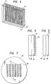
- F ig. 6 illustrates a diffusion surface 24 arranged such that a displayed three-dimensional image will not appear inverted when it is viewed at in a lateral direction rather than head on-
- the arrangement of Fig. 6 has been proposed by Japanese Laid-Open Patent Publication No. 50-96228.
- Other proposals for preventing three-dimensional images from appearing inverted are disclosed in Examined Japanese Utility Model Publication No. 51-213 and Japanese Laid-open Patent Publications No. 50-96227.
- the construction of the diffusion surface per se is not part of the present invention.
- Fig. 7 shows a three-dimensional image display apparatus according to another embodiment of the present invention. More specifically, Fig. 7 illustrates a phosphor screen 26 of a projection image tube corresponding to the projection image tube 20 or 22 shown in Fig. 3. While the phosphor screen illustrated in Fig. 3 emits light over its entire surface, the phosphor screen of Fig. 7 is composed of vertical stripes 28 which emit light separated by vertical stripes 27 which emit no light. This arrangement is effected by a uniform phosphor screen 26 and a vertically striped shield plate 25 positioned directly in front of the phosphor screen 2 6 . Accordingly, a vertically striped image is produced. Images from the left-eye and right-eye image tubes are projected onto the diffusion surface 15 in overlapping interleaved stripes, as described before. With this embodiment, no shield plate 16 as shown in Figs. 3 and 4 is required.
- a vertically striped electrode may be provided for shielding the electron beam falling on the phosphor screen 26.
- the portions indicated by 27 in Fig. 7 contain luminescent phosphor but emit no light. The manner in which images are projected onto the diffusion surfaoe 15 remains as described above.
- a beam blanking process can be employed whereby the electron beam which scans the phosphor screen 26 is periodically cut off by an external circuit for producing a vertically striped image.
- This process is also capable of producing vertically striped left-eye and right-eye images which can be projected onto the diffusion surface 15 in the desired overlapping, interleaved pattern. Any of the arrangements described above allow the viewer to observe a three-dimensional image at the viewing points 11 and 12.
- the present invention is not to be interpreted as being limited to the foregoing embodiments, but includes various modifications.
- Three-dimensional images can be viewed in color by employing color image tubes instead of monochrome image tubes as the projection image tubes 20 and 22.
- Figs. 8A and 8B Three-dimensional images can be displayed in color by the system shown in Figs. 8A and 8B. More specifically, the ararangement of Fig. 8A is similar to that of Fig. 3, but differs therefrom in that color filters 31 and 34 are added.
- Fig. 8A is a plan view of this sytem, while Fig. 8B is a side elevational view.
- a projection image tube 36 emits red light which is projected through a projection lens 35 and a red-pass filter 34 onto a diffusion surface 15.
- a projection image tube 39, a projection lens 38, and a green-pass filtei 37 serve to project green light onto the diffusion surface 15.
- a projection image tube 42, a projection lens 41, and a blue-pass filter 4 2 serve to project green light onto the diffusion surface 15.
- the projection image tubes and related components shown in Fig. 8B are used only for forming the right-eye image.
- a projection image tube 33, a projection lens 32, and a red-pass filter 31 illustrated in Fig. 8A serve to project red light onto the diffusion curfaao 15 for a left-eye image.
- Below the projection image tube 33, the projection lens 32, and the red-pass filter 31 there are provided similar components for projecting images of green and blue light for the left eye using the same arrangement as shown in Fig. 8B.
- the vertically striped images of red, green and blue light in Fig. 8B are projected onto the transmissive diffusion surface 15, and the imagea of three colors in one set are overlapped as one vertical stripe image which appears as a colored image.
- the images thus formed appear as a colored three-dimensional image at the viewing points 11 and 12.
- the projection image tubes for red, green and blue light are arranged in Fig. 8B in the stated order in the vertical direotion, the projection image tubes are not limited to such an order, and may be arranged in any other sequence. Also, the projection image tubes for the left and right eyes need not be arranged in the stated order, and may be in any desired sequence.
- Schmidt optical systems including projection optics may be employed as the projection image tubes 20, 22, 33 and 36, 39, 42 as shown in Figs. 3 and 8.
- the optical components 19, 21 and 32, 35, 38, 41 indicated in Figs. 3 and 8 may be dispensed with, and the shield plate placed directly in front of the phosphor screen surface doubles as an electrode plate for shielding the electron beam.
- the latter effect is due to the fact that the electron beam strikes the phosphor screen in the same direction with respect to the plane of the phosphor screen as that in which light is emitted from the phosphor screen.
- projection image tubes While two projection image tubes are shown in Figs. 3 and 8, as many projection image tubes as desired may be disposed in the lateral direction, provided a plurality of such projection image tubes are included.
- the intervals between slits in the shield plate 16 should of course be correspondingly decreased to reduce the image overlap on the diffusion surface.
- Fig. 9 is a side elevational view of a projection television apparatus according to the present invention.
- the projection television apparatus shown in Fig. 9 has a screen 31, cathode-ray tubes 32, 33 and 34 for displaying images in red, green, and blue, respectively, and the optical systems 35, 36 and 37 for projecting the color images displayed on the cathode-ray tubes 32, 33 and 34, respectively, onto the screen 31.
- the light rays representative of the color images projected onto the screen 31 have different incident angles.
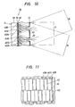
- Fig. 10 is a fragmentary enlarged cross-sectional view of the screen 31 illustrated in Fig. 9.
- a substrate 38 which is made of glass or synthetic resin capable of transmitting light, has a surface A where a projected image is observed.
- the substrate 38 is coated on the entirety of its reverse side with a uniform light-diffusing layer 39 serving to mix colors well and thus enlarge the range in which images can be observed.
- a light-emitting layer 40 coated on the surface of the light-diffusing layer 39 is composed of repeating sequences of phosphor stripes 40R, 40G and 40B respectively emitting the three primary colors of light, that is, red, green, and blue.
- a shield plate 41 is spaced a predetermined distance from the light-emitting layer 40 in a confronting relation thereto.
- the shield plate 41 has a multiplicity of apertures 42 formed therein for guiding images projected from the cathode-ray tubes 32 to 34 shown in Fig. 9 as image projectors onto the phosphor stripes 40R, 40G and 40B so that the images will not overlap each other. Also, designated in Fig. 9, at R, G and B, are light rays of projected images in red, green and blue, respectively, which are generated from the cathode-ray tubes 32, 33 and 34 via their respective optical systems.
- the projection television apparatus of the foregoing embodiment operates as follows.
- the red image produced by the oathode-ray tube 32 is projected by the optical system 35 onto the screen 31. Since the shield plate 4 1 is disposed in front of the light-emitting layer 40 of the screen 31, only a portion of the light rays R of the red image passes through the apertures 42 in the shield plate 41 and falls on the phosphor stripes 40R, as indicated by the arrows R 1 and R 2 in Fig. 10. As a result, the phosphor stripes 40R emit red light due to excitation by the light rays R of the red image.
- the light rays G of the green image and the light rays B of the blue image are supplied from the cathode-ray tubes 33 and 34, respectively, and fall on the respective phosphor stripes 40G and 40B, passing through the apertures 42 in the shield plate 41.
- the phosphor stripes 40G and 40B are thus excited to emit green and blue light.
- Light rays in the three primaries thus emitted by the phosphor stripes 40R, 40G and 40B are diffused by the light diffusion layer 39 so as to be mixed together and enlarge the range in which the image can be observed. Thereafter, the light rays pass through the transmissive substrate 38 toward the viewer.
- projected images can be displayed in color at a high brightness level by light rays of the respective image colors which are, in turn, produced by light rays (which may be visible light infrared or ultraviolet radiation, for example) emitted from the oathode-ray tubes 42, 43 and 44 which excite the phosphor stripes 40R, 40G and 40B.
- light rays which may be visible light infrared or ultraviolet radiation, for example
- each of the phosphor stripes should be peripherally enclosed by a light-absorbing material such as carbon, or the viewing surface of the substrate 31 should be arranged such that it will absorb extraneous light falling thereon.
- Fig. 12 is a cross-sectional view, similar to the view of Fig. l g , illustrating a screen which can be used in the three-dimensional displaying apparatus of Fig. 3.
- the image source may emit any of visible light, infrared light or ultraviolet light.
- stripes 56, 57 and 58 of fluorescent material for emitting red, green and blue light, respectively are disposed on the face of a base of substrate adjacent the shield plate 41.
- a diffusion layer 54 or the like is disposed under the fluorescent stripes 56, 57 and 58.
- a lenticular lens is provided.
- Fig. 13 shows a modification of the screen of Fig. 12 in which the light-emitting portions for each of red, green and blue are offset in the longitudinal diretion with respect to one another.
- the purpose for the relative offsets is to compensate for differences in wavelengths among the red, green and blue light. More particularly, the radius of the curvature of the lenticular lens is constant at any portion thereon, but the wavelength of the image portions in the three different primary colors are different, so that the reflective index of the lenses different for these three colors, thereby producing a displacement of the three images. Such displacement is compensated for with the arrangement of Fig. 13.
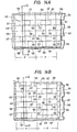
- Figs. 14A and 14B are front views of a screen of the type of Figs. 12 or 13.
- the light-emitting stripes 56, 57 and 58 are arranged in a regular rectangular pattern, while in the arrangement of Fig. 14B, an offset is provided between pairs of two adjacent columns of the stripes.
- images in the three primary colors are displayed by three respective cathode-ray tubes, and light rays representative of such images are projected from different positions through apertures in a shield plate onto corresponding light-emitting portions of phosphor stripes which constitute a screen, thereby causing the phosphor stripes to display a color image which can be directly observed. Therefore, the displayed image is much brighter than in a conventional device.
Landscapes
- Engineering & Computer Science (AREA)
- Multimedia (AREA)
- Signal Processing (AREA)
- Testing, Inspecting, Measuring Of Stereoscopic Televisions And Televisions (AREA)
Priority Applications (2)
| Application Number | Priority Date | Filing Date | Title |
|---|---|---|---|
| EP84300211A EP0151331B1 (fr) | 1984-01-13 | 1984-01-13 | Appareil de projection d'image |
| DE8484300211T DE3482544D1 (de) | 1984-01-13 | 1984-01-13 | Bildprojektionsgeraet. |
Applications Claiming Priority (1)
| Application Number | Priority Date | Filing Date | Title |
|---|---|---|---|
| EP84300211A EP0151331B1 (fr) | 1984-01-13 | 1984-01-13 | Appareil de projection d'image |
Publications (2)
| Publication Number | Publication Date |
|---|---|
| EP0151331A1 true EP0151331A1 (fr) | 1985-08-14 |
| EP0151331B1 EP0151331B1 (fr) | 1990-06-13 |
Family
ID=8192531
Family Applications (1)
| Application Number | Title | Priority Date | Filing Date |
|---|---|---|---|
| EP84300211A Expired - Lifetime EP0151331B1 (fr) | 1984-01-13 | 1984-01-13 | Appareil de projection d'image |
Country Status (2)
| Country | Link |
|---|---|
| EP (1) | EP0151331B1 (fr) |
| DE (1) | DE3482544D1 (fr) |
Cited By (6)
| Publication number | Priority date | Publication date | Assignee | Title |
|---|---|---|---|---|
| GB2186147A (en) * | 1986-01-30 | 1987-08-05 | Quantel Ltd | Image display system |
| GB2206763A (en) * | 1987-07-10 | 1989-01-11 | Adrian Robert Leigh Travis | Three dimensional display apparatus |
| EP0505616A1 (fr) * | 1990-12-03 | 1992-09-30 | Walter Stadler | Méthode pour la représentation et la restitution dans l'espace d'images mobiles tridimensionnelles sur des dispositifs d'affichage |
| WO1992022989A1 (fr) * | 1991-06-12 | 1992-12-23 | Sung Lee | Enregistrement et reproduction d'une image tridimensionnelle |
| WO1997002709A3 (fr) * | 1995-07-05 | 1997-03-13 | Philips Electronics Nv | Appareil d'affichage autostereoscopique |
| GB2469535B (en) * | 2009-04-17 | 2013-10-09 | Ilit Technologies Ltd | Light reactive media |
Citations (2)
| Publication number | Priority date | Publication date | Assignee | Title |
|---|---|---|---|---|
| US3858001A (en) * | 1973-05-11 | 1974-12-31 | Honeywell Inc | Stereoscopic display system |
| US4054907A (en) * | 1975-02-28 | 1977-10-18 | Sony Corporation | Back projection apparatus |
Family Cites Families (1)
| Publication number | Priority date | Publication date | Assignee | Title |
|---|---|---|---|---|
| US3674921A (en) * | 1969-11-12 | 1972-07-04 | Rca Corp | Three-dimensional television system |
-
1984
- 1984-01-13 EP EP84300211A patent/EP0151331B1/fr not_active Expired - Lifetime
- 1984-01-13 DE DE8484300211T patent/DE3482544D1/de not_active Expired - Lifetime
Patent Citations (2)
| Publication number | Priority date | Publication date | Assignee | Title |
|---|---|---|---|---|
| US3858001A (en) * | 1973-05-11 | 1974-12-31 | Honeywell Inc | Stereoscopic display system |
| US4054907A (en) * | 1975-02-28 | 1977-10-18 | Sony Corporation | Back projection apparatus |
Non-Patent Citations (1)
| Title |
|---|
| PROCEEDINGS OF THE IEEE, vol. 68, no. 5, May 1980, pages 548-564, IEEE, New York, US; T. OKOSHI: "Three-dimensional displays" * |
Cited By (9)
| Publication number | Priority date | Publication date | Assignee | Title |
|---|---|---|---|---|
| GB2186147A (en) * | 1986-01-30 | 1987-08-05 | Quantel Ltd | Image display system |
| GB2206763A (en) * | 1987-07-10 | 1989-01-11 | Adrian Robert Leigh Travis | Three dimensional display apparatus |
| GB2206763B (en) * | 1987-07-10 | 1991-07-31 | Adrian Robert Leigh Travis | Three dimensional display apparatus |
| EP0505616A1 (fr) * | 1990-12-03 | 1992-09-30 | Walter Stadler | Méthode pour la représentation et la restitution dans l'espace d'images mobiles tridimensionnelles sur des dispositifs d'affichage |
| WO1992022989A1 (fr) * | 1991-06-12 | 1992-12-23 | Sung Lee | Enregistrement et reproduction d'une image tridimensionnelle |
| US5576783A (en) * | 1991-06-12 | 1996-11-19 | Lee; Sung | Recording and reproducing a 3-dimensional image |
| WO1997002709A3 (fr) * | 1995-07-05 | 1997-03-13 | Philips Electronics Nv | Appareil d'affichage autostereoscopique |
| KR100418146B1 (ko) * | 1995-07-05 | 2004-04-29 | 코닌클리케 필립스 일렉트로닉스 엔.브이. | 자동입체표시장치 |
| GB2469535B (en) * | 2009-04-17 | 2013-10-09 | Ilit Technologies Ltd | Light reactive media |
Also Published As
| Publication number | Publication date |
|---|---|
| DE3482544D1 (de) | 1990-07-19 |
| EP0151331B1 (fr) | 1990-06-13 |
Similar Documents
| Publication | Publication Date | Title |
|---|---|---|
| US4872750A (en) | Image projection apparatus | |
| US4737840A (en) | Color image projection apparatus with a screen including a shield plate, light-emitting layer and diffusion surface to expand viewing range of bright pictures | |
| US5036385A (en) | Autostereoscopic display with multiple sets of blinking illuminating lines and light valve | |
| US4829365A (en) | Autostereoscopic display with illuminating lines, light valve and mask | |
| US5392140A (en) | Optical device with two lens arrays with the second array pitch an integral multiple of the first array pitch | |
| US5040878A (en) | Illumination for transmissive displays | |
| US5410345A (en) | Stroboscopic illumination system for video displays | |
| CN103744262B (zh) | 由拼接的发光屏幕构成的组合屏幕 | |
| US4054907A (en) | Back projection apparatus | |
| EP0051976A2 (fr) | Réfracteur optique pour diffusion de lumière | |
| EP0316465B1 (fr) | Dispositif d'affichage autostéréoscopique avec des lignes d'illumination et des valves de lumière | |
| JP2955327B2 (ja) | 三次元画像表示装置 | |
| US2260228A (en) | Means for projecting images | |
| WO1995033227A1 (fr) | Dispositif de projection d'images | |
| US5015999A (en) | Display unit | |
| WO1990005429A1 (fr) | Systeme d'affichage sequentiel d'images en couleur | |
| JP2002287090A (ja) | 三次元映像表示装置及び点状光出射部材及び点状光透過部材 | |
| EP0151331B1 (fr) | Appareil de projection d'image | |
| GB2131258A (en) | Image display apparatus | |
| US6462869B1 (en) | Projection screen and system for large-surface images | |
| EP0471478B1 (fr) | Appareil d'affichage à grand écran | |
| JP2019139227A (ja) | 立体映像液晶表示装置 | |
| US5971547A (en) | Astigmatic lenticular projector system | |
| EP0290290B1 (fr) | Projecteur à valve de lumière d'efficacité de la source lumineuse intensifiée | |
| JPH08304735A (ja) | 立体映像表示装置 |
Legal Events
| Date | Code | Title | Description |
|---|---|---|---|
| PUAI | Public reference made under article 153(3) epc to a published international application that has entered the european phase |
Free format text: ORIGINAL CODE: 0009012 |
|
| AK | Designated contracting states |
Designated state(s): DE GB NL |
|
| 17P | Request for examination filed |
Effective date: 19860212 |
|
| 17Q | First examination report despatched |
Effective date: 19890320 |
|
| RAP1 | Party data changed (applicant data changed or rights of an application transferred) |
Owner name: NEC HOME ELECTRONICS, LTD. |
|
| GRAA | (expected) grant |
Free format text: ORIGINAL CODE: 0009210 |
|
| AK | Designated contracting states |
Kind code of ref document: B1 Designated state(s): DE GB NL |
|
| REF | Corresponds to: |
Ref document number: 3482544 Country of ref document: DE Date of ref document: 19900719 |
|
| PGFP | Annual fee paid to national office [announced via postgrant information from national office to epo] |
Ref country code: GB Payment date: 19910102 Year of fee payment: 8 |
|
| PGFP | Annual fee paid to national office [announced via postgrant information from national office to epo] |
Ref country code: NL Payment date: 19910131 Year of fee payment: 8 Ref country code: DE Payment date: 19910131 Year of fee payment: 8 |
|
| PLBE | No opposition filed within time limit |
Free format text: ORIGINAL CODE: 0009261 |
|
| STAA | Information on the status of an ep patent application or granted ep patent |
Free format text: STATUS: NO OPPOSITION FILED WITHIN TIME LIMIT |
|
| 26N | No opposition filed | ||
| PG25 | Lapsed in a contracting state [announced via postgrant information from national office to epo] |
Ref country code: GB Effective date: 19920113 |
|
| PG25 | Lapsed in a contracting state [announced via postgrant information from national office to epo] |
Ref country code: NL Effective date: 19920801 |
|
| GBPC | Gb: european patent ceased through non-payment of renewal fee | ||
| NLV4 | Nl: lapsed or anulled due to non-payment of the annual fee | ||
| PG25 | Lapsed in a contracting state [announced via postgrant information from national office to epo] |
Ref country code: DE Effective date: 19921001 |