EP0151373A1 - Dispositif pour faire avancer le papier photographique dans une imprimante - Google Patents
Dispositif pour faire avancer le papier photographique dans une imprimante Download PDFInfo
- Publication number
- EP0151373A1 EP0151373A1 EP84830298A EP84830298A EP0151373A1 EP 0151373 A1 EP0151373 A1 EP 0151373A1 EP 84830298 A EP84830298 A EP 84830298A EP 84830298 A EP84830298 A EP 84830298A EP 0151373 A1 EP0151373 A1 EP 0151373A1
- Authority
- EP
- European Patent Office
- Prior art keywords
- cutter
- photographic paper
- exposure window
- sensors
- paper
- Prior art date
- Legal status (The legal status is an assumption and is not a legal conclusion. Google has not performed a legal analysis and makes no representation as to the accuracy of the status listed.)
- Withdrawn
Links
- 230000033001 locomotion Effects 0.000 claims abstract description 25
- 238000006073 displacement reaction Methods 0.000 claims abstract description 16
- 230000003534 oscillatory effect Effects 0.000 claims description 7
- 230000005540 biological transmission Effects 0.000 claims description 3
- 230000000694 effects Effects 0.000 claims description 2
- 238000000605 extraction Methods 0.000 description 2
- 101100345589 Mus musculus Mical1 gene Proteins 0.000 description 1
- 230000008878 coupling Effects 0.000 description 1
- 238000010168 coupling process Methods 0.000 description 1
- 238000005859 coupling reaction Methods 0.000 description 1
- 230000008030 elimination Effects 0.000 description 1
- 238000003379 elimination reaction Methods 0.000 description 1
- 210000003414 extremity Anatomy 0.000 description 1
- 210000003141 lower extremity Anatomy 0.000 description 1
- 238000012986 modification Methods 0.000 description 1
- 230000004048 modification Effects 0.000 description 1
- 230000003287 optical effect Effects 0.000 description 1
Images
Classifications
-
- G—PHYSICS
- G03—PHOTOGRAPHY; CINEMATOGRAPHY; ANALOGOUS TECHNIQUES USING WAVES OTHER THAN OPTICAL WAVES; ELECTROGRAPHY; HOLOGRAPHY
- G03B—APPARATUS OR ARRANGEMENTS FOR TAKING PHOTOGRAPHS OR FOR PROJECTING OR VIEWING THEM; APPARATUS OR ARRANGEMENTS EMPLOYING ANALOGOUS TECHNIQUES USING WAVES OTHER THAN OPTICAL WAVES; ACCESSORIES THEREFOR
- G03B27/00—Photographic printing apparatus
- G03B27/32—Projection printing apparatus, e.g. enlarger, copying camera
- G03B27/52—Details
- G03B27/58—Baseboards, masking frames, or other holders for the sensitive material
- G03B27/587—Handling photosensitive webs
- G03B27/588—Supply rolls; Cutting arrangements
-
- G—PHYSICS
- G03—PHOTOGRAPHY; CINEMATOGRAPHY; ANALOGOUS TECHNIQUES USING WAVES OTHER THAN OPTICAL WAVES; ELECTROGRAPHY; HOLOGRAPHY
- G03B—APPARATUS OR ARRANGEMENTS FOR TAKING PHOTOGRAPHS OR FOR PROJECTING OR VIEWING THEM; APPARATUS OR ARRANGEMENTS EMPLOYING ANALOGOUS TECHNIQUES USING WAVES OTHER THAN OPTICAL WAVES; ACCESSORIES THEREFOR
- G03B27/00—Photographic printing apparatus
- G03B27/32—Projection printing apparatus, e.g. enlarger, copying camera
- G03B27/46—Projection printing apparatus, e.g. enlarger, copying camera for automatic sequential copying of different originals, e.g. enlargers, roll film printers
- G03B27/462—Projection printing apparatus, e.g. enlarger, copying camera for automatic sequential copying of different originals, e.g. enlargers, roll film printers in enlargers, e.g. roll film printers
Definitions
- the invention relates to a device for moving photographic paper, or equivalent photosensitive material, in a printer.
- All the said known items of equipment effect the driving of the web of photographic paper by means of a pair of oppositely placed rollers : the photographic paper, inserted in between the said rollers, is made to move forward each time the said rollers are carried in motion. In this way, the photographic paper is dragged forward and thrust alternatively into the exposure position and into the subsequent cutting'position.
- the positioning of the photographic paper at points corresponding to the exposure window and to the cutter is achieved by the movement of the said rollers being subjected to control means of the type able to detect the extent of the rotation of the said rollers and to correlate the said rotation with the distance forward required for the paper.
- the position of the photographic paper is calculated solely on the basis of the rotation of the drive rollers, and thus on the supposition that no skidding occurs between the paper and the said rollers.
- the said items of equipment show the said premise to be wrong : skidding and slipping between the rollers and the paper take place in many instances and, indeed, the faster the pace of the printer or, in other words, the greater the volume of work and the financial importance of the said printer, the more accentuated is the said phenomenon.
- the technical task'that constitutes the basis of the invention is, in view of the foregoing, to eliminate the problems outlined above and to construct a device able to position, with precision and absolute reliability, the photographic paper in both the exposure position and the cutting position thereof, with the elimination of false positions resulting from slipping occurring between the drive elements and the photographic paper undergoing forward movement.
- One important object of the invention within the framework of the said technical task, is to devise a device able to adapt itself to any variation in the size of the exposure window, with the automatic and precise displacement of the means responsible for the subsequent phases in the treatment of the photographic paper.
- Another, though not final, object of the invention is to make available a system that is simple, inexpensive and easily realizable by industries in the field concerned.
- the device according to the invention for moving photographic paper in a printer impervious to light and provided with photographic equipment facing an exposure window, and with a cutter for the said photographic paper
- the said device comprising elements for carrying forward a web of the said photographic paper from a commencement reel to the said exposure window and thence to the said cutter, and for carrying sheets of the said photographic paper from the said cutter towards the outside of the said printer; and, furthermore, means for controlling the displacements of the said photographic paper and for operating the said drive elements in a way whereby the said web is made to move forward in steps proportional to the size of the said exposure window; and wherein the said control means comprise a plurality of sensors placed downstream of the said cutter, in the forward movement direction of the said web, able to detect the position of the cut edges of the said sheets and, in consequence, to bring about the non-operation of the said drive elements.
- the said control means comprise at least one sensor placed downstream of the said cutter at a distance away from the said exposure window identical to or a multiple of the size of this, and a second sensor, downstream of the former in the forward movement direction of the said sheets, a distance away from the first sensor identical to the spacing between the said exposure window and the said cutter.
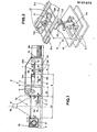
- the movement device according tb the invention shown globally at 1, is inserted in a printer 2 in itself known.
- the said printer 2 is, in brief, provided with a fixed supporting frame 3 equipped with a casing 4 that is impervious to light, and with a cassette 5, also impervious to light, in which is inserted a commencement roll 6 of photographic paper 6a.
- a cassette 5 also impervious to light, in which is inserted a commencement roll 6 of photographic paper 6a.
- an exposure window 7 is provided between the cassette 5 and the casing 4 between the cassette 5 and the casing 4 .
- the photographic paper 6a unwound from the roll 6 is exposed in the exposure window 7.
- the printer 2 comprises a cutter 9 able to subdivide the web of photographic paper 6a unwound from the roll 6 into a number of sheets 6b cut to the size of the exposure window 7.
- the printer 2 terminates, in the embodiment illustrated, at a tray 10 for collecting and stacking the sheets 6b of photographic paper, though it is obvious that the printer can be linked up directly to a machine for developing the sheets.
- the movement device 1 forming the subject of the invention essentially comprises elements for driving the photographic paper and means for controlling the displacements of the said photographic paper. The latter operate the said drive elements.
- the drive means comprise, in the technical solution described herein, a pair of oppositely placed rollers 11 in between which is unwound the web of,photographic paper.
- the rollers 11 are, in fact, inserted in the casing 4 between the exposure window 7 and the cutter 9. Downstream of the latter, in the forward movement direction of the web of photographic paper, provision is made for an auxiliary conveyor 12, virtually in the form of conveyor belts 12a, by which the cut sheets are made to move forward towards the tray 10.
- An original aspect of the invention is that the auxiliary conveyor 12 is able to give the cut sheets a traversing speed slightly greater than that of the web that slides between the rollers 11, in such a way as to create consecutive sheets slightly apart.
- control means envisaged for the invention are constituted by sensors 13, preferably microswitches, placed downstream of the cutter 9 in the region of the auxiliary conveyor 12.
- the said sensors 13 are set to detect the position of the edges of the sheets moved by the auxiliary conveyor 12 and, in consequence, to bring about the non-operation of the drive elements, in particular the rollers 11. Depending on the requirements, the number of the said sensors 13 can be much greater. However, shown in the figures is a tech- , nical solution, in itself advantageous, based on the use of only two sensors, namely a first sensor 13a and a second sensor 13b, the latter spaced away from the former in the movement direction of the photographic paper.
- the first sensor 13a is placed downstream of the cutter 9, in the forward movement direction of the phatographic paper, at a distance X (see Figure 1) from the most adjacent edge 7a of the exposure'window 7 identical to or a multiple of the size X 1 of the said exposure window 7.
- the second sensor 13b is placed at a distance A from the the first sensor 13a identical to the distance A between the line of action of the cutter 9 and the previously mentioned most adjacent edge 7a of the exposure window 7.
- the said sensors determine the cessation in the rotation of the rollers 11 and that the resumption of the rotation of these be determined by the operation of the photographic equipment 8 and of the cutter 9.
- the invention also makes provision for the movement device 1 to be suited automatically to variations in the dimensions of the exposure window 7.
- the sensors 13 and the cutter 9 are, in fact, movable and inserted in a slide 14 that moves smoothly in the frame 3, in a direction parallel to the forward movement direction of the photographic paper.
- the movement of the sensors 13 and of the cutter 9 is determined by mechanical means of transmission set in action directly with the displacements of the margins of the exposure window 7.
- the exposure window 7 is delimited, in the forward movement direction of the photographic paper, by a cover 15 placed above the cassette 5, and by one extremity of the said slide 14 above which overhangs the casing 4.
- the expansion of the exposure window 7 envisages, therefore, the slide 14 being moved away from or being brought towards the optical projection axis 16 through, for example, an adjusting screw 17 controlled by a purposely provided handwheel 18.
- the displacement of the slide 14 determines an identical displacement of the cutter 9.
- the displacement of the sensors 13 is, instead only indirectly imposed by the slide 14 : the said sensors are, in fact, connected to a positioning device 19 shown by itself in Figure 2.
- the said device comprises an oscillatory arm 20 that supports at the top, through a cross member 21 loosely pivoted thereto, the sensors 13a and 13b (see again Figure 2).
- the lower extremity of the said arm 20 is, instead, pivotally connected to the fixed frame 3, and the connection with the slide 14 is realized only in an intermediate position thanks to an axial slot-pin coupling.
- the oscillatory arm 20 has, in fact, machined in it an axial slot 22 into which is inserted a pin. 23 integral with the slide 14.
- the position of the pin 23 along the oscillatory arm 20 determines the final displacement of the sensors 13.
- the photographic paper is unwound from the roll 6 by the rollers 11 and is subsequently carried to the exposure window 7 and to the cutter 9, after which the auxiliary conveyor 12 preferably operates.
- the first microswitch 13a halts the flow of. photographic paper once one edge of this arrives in proximity and determines the starting up of the photographic equipment 8. Following this, the forward movement of the paper is resumed automatically until the second sensor 13b is engaged, this in turn halting the flow of paper and determining the operation of the cutter 9.
- the paper is made to move forward a distance A1 ( Figure 1).
- the second sensor 13b placed an overall distance equal to A 1 +X away from the exposure window, operates.
- the subsequent forward movement is effected for a distance X-Aup until the first sensor 13a is made to operate, and this determines the operation anew of the photographic equipment 8.
- the device according to the invention attains the objects proposed.
Landscapes
- Physics & Mathematics (AREA)
- General Physics & Mathematics (AREA)
- Advancing Webs (AREA)
- Handling Of Sheets (AREA)
Applications Claiming Priority (2)
| Application Number | Priority Date | Filing Date | Title |
|---|---|---|---|
| IT363883 | 1983-11-25 | ||
| IT03638/83A IT1171977B (it) | 1983-11-25 | 1983-11-25 | Dispositivo di trasporto di carta fotografica in una stampatrice fotografica |
Publications (1)
| Publication Number | Publication Date |
|---|---|
| EP0151373A1 true EP0151373A1 (fr) | 1985-08-14 |
Family
ID=11110996
Family Applications (1)
| Application Number | Title | Priority Date | Filing Date |
|---|---|---|---|
| EP84830298A Withdrawn EP0151373A1 (fr) | 1983-11-25 | 1984-11-02 | Dispositif pour faire avancer le papier photographique dans une imprimante |
Country Status (2)
| Country | Link |
|---|---|
| EP (1) | EP0151373A1 (fr) |
| IT (1) | IT1171977B (fr) |
Citations (5)
| Publication number | Priority date | Publication date | Assignee | Title |
|---|---|---|---|---|
| US3564960A (en) * | 1969-04-18 | 1971-02-23 | Gaf Corp | Automatic copy machine copy paper length error compensating system |
| DE2424624A1 (de) * | 1973-05-21 | 1974-12-12 | Agfa Gevaert Ag | Verfahren zur herstellung entwickelbarer elektrostatischer ladungsbilder |
| US4046470A (en) * | 1973-09-29 | 1977-09-06 | Minolta Camera Kabushiki Kaisha | Printing paper cutting device for an electrical copier |
| DE2938576A1 (de) * | 1978-09-25 | 1980-04-03 | Minnesota Mining & Mfg | Kopiermaschine mit automatischer kopierpapierzufuhr von einer vorratsrolle, mit einer schneidvorrichtung und einer steuerschaltung |
| GB2047210A (en) * | 1979-04-10 | 1980-11-26 | Mita Industrial Co Ltd | Controlling web cutting in copying apparatus |
-
1983
- 1983-11-25 IT IT03638/83A patent/IT1171977B/it active
-
1984
- 1984-11-02 EP EP84830298A patent/EP0151373A1/fr not_active Withdrawn
Patent Citations (5)
| Publication number | Priority date | Publication date | Assignee | Title |
|---|---|---|---|---|
| US3564960A (en) * | 1969-04-18 | 1971-02-23 | Gaf Corp | Automatic copy machine copy paper length error compensating system |
| DE2424624A1 (de) * | 1973-05-21 | 1974-12-12 | Agfa Gevaert Ag | Verfahren zur herstellung entwickelbarer elektrostatischer ladungsbilder |
| US4046470A (en) * | 1973-09-29 | 1977-09-06 | Minolta Camera Kabushiki Kaisha | Printing paper cutting device for an electrical copier |
| DE2938576A1 (de) * | 1978-09-25 | 1980-04-03 | Minnesota Mining & Mfg | Kopiermaschine mit automatischer kopierpapierzufuhr von einer vorratsrolle, mit einer schneidvorrichtung und einer steuerschaltung |
| GB2047210A (en) * | 1979-04-10 | 1980-11-26 | Mita Industrial Co Ltd | Controlling web cutting in copying apparatus |
Also Published As
| Publication number | Publication date |
|---|---|
| IT8303638A0 (it) | 1983-11-25 |
| IT1171977B (it) | 1987-06-10 |
Similar Documents
| Publication | Publication Date | Title |
|---|---|---|
| US3763728A (en) | Bimodal film cutter adapted to handle different film widths | |
| EP2749018B1 (fr) | Procédé et appareil de numérisation en continu d'un film composé d'images en mouvement | |
| EP0151373A1 (fr) | Dispositif pour faire avancer le papier photographique dans une imprimante | |
| US3807264A (en) | Web severing apparatus | |
| JP7141345B2 (ja) | カッティング装置 | |
| JPS59138559A (ja) | 感光材料切断移送装置 | |
| JPS6328300B2 (fr) | ||
| JPS62103628A (ja) | 印画紙保留装置 | |
| EP0107936A1 (fr) | Colleuse pour matériaux photographiques | |
| JPH05270710A (ja) | ウェブの蛇行修正機構 | |
| JPS6122654B2 (fr) | ||
| US4131041A (en) | Collector forming an accumulating stack from successively received severed sections of photographic strip | |
| EP0562675B1 (fr) | Guillotine flexible | |
| JP7239334B2 (ja) | 自動壁紙糊付機 | |
| US3699834A (en) | Bimodal film cutter adapted to handle different film widths | |
| US2607588A (en) | Web centering device | |
| US4650314A (en) | Film inspection machine | |
| JP2628097B2 (ja) | 印画紙焼付装置 | |
| US3394040A (en) | Film splicer | |
| JP2724487B2 (ja) | 連続用紙切断装置 | |
| JPH0562968B2 (fr) | ||
| JPH0740288A (ja) | フイルムの耳端トリミング装置 | |
| JPS6270155A (ja) | 印画紙保留装置 | |
| JPH02285467A (ja) | 情報検索装置 | |
| EP0148734A2 (fr) | Unité de service destinée à convertir en paquets la bande de papier traitée par une imprimante alimentée avec un support préformé |
Legal Events
| Date | Code | Title | Description |
|---|---|---|---|
| PUAI | Public reference made under article 153(3) epc to a published international application that has entered the european phase |
Free format text: ORIGINAL CODE: 0009012 |
|
| AK | Designated contracting states |
Designated state(s): AT BE CH DE FR GB LI LU NL SE |
|
| 17P | Request for examination filed |
Effective date: 19850722 |
|
| 17Q | First examination report despatched |
Effective date: 19870119 |
|
| STAA | Information on the status of an ep patent application or granted ep patent |
Free format text: STATUS: THE APPLICATION HAS BEEN WITHDRAWN |
|
| 18W | Application withdrawn |
Withdrawal date: 19870715 |
|
| RIN1 | Information on inventor provided before grant (corrected) |
Inventor name: VALENTINUZZI, LUCIANO Inventor name: POLI, BRUNO |