EP0151379A2 - Installation pour la fabrication de briques moulées en béton aéré - Google Patents
Installation pour la fabrication de briques moulées en béton aéré Download PDFInfo
- Publication number
- EP0151379A2 EP0151379A2 EP84890239A EP84890239A EP0151379A2 EP 0151379 A2 EP0151379 A2 EP 0151379A2 EP 84890239 A EP84890239 A EP 84890239A EP 84890239 A EP84890239 A EP 84890239A EP 0151379 A2 EP0151379 A2 EP 0151379A2
- Authority
- EP
- European Patent Office
- Prior art keywords
- molds
- ring
- turntable
- plant according
- base
- Prior art date
- Legal status (The legal status is an assumption and is not a legal conclusion. Google has not performed a legal analysis and makes no representation as to the accuracy of the status listed.)
- Granted
Links
- 239000011459 moulded brick Substances 0.000 title 1
- 239000011381 foam concrete Substances 0.000 claims abstract description 18
- 230000002093 peripheral effect Effects 0.000 claims description 3
- 238000009434 installation Methods 0.000 claims 2
- 238000004519 manufacturing process Methods 0.000 abstract description 4
- 238000010924 continuous production Methods 0.000 abstract description 2
- 230000001419 dependent effect Effects 0.000 abstract description 2
- 239000004575 stone Substances 0.000 description 9
- 238000011282 treatment Methods 0.000 description 5
- 239000006260 foam Substances 0.000 description 4
- 239000000654 additive Substances 0.000 description 2
- 239000003795 chemical substances by application Substances 0.000 description 2
- 238000004140 cleaning Methods 0.000 description 2
- 238000001816 cooling Methods 0.000 description 2
- 230000008878 coupling Effects 0.000 description 2
- 238000010168 coupling process Methods 0.000 description 2
- 238000005859 coupling reaction Methods 0.000 description 2
- 238000005520 cutting process Methods 0.000 description 2
- 238000010438 heat treatment Methods 0.000 description 2
- 238000004321 preservation Methods 0.000 description 2
- 238000011144 upstream manufacturing Methods 0.000 description 2
- 230000001133 acceleration Effects 0.000 description 1
- 239000011449 brick Substances 0.000 description 1
- 239000004568 cement Substances 0.000 description 1
- 239000004927 clay Substances 0.000 description 1
- 239000004567 concrete Substances 0.000 description 1
- 230000007812 deficiency Effects 0.000 description 1
- 230000000694 effects Effects 0.000 description 1
- 239000007788 liquid Substances 0.000 description 1
- 239000000463 material Substances 0.000 description 1
- 239000000203 mixture Substances 0.000 description 1
- 239000008262 pumice Substances 0.000 description 1
- 230000000284 resting effect Effects 0.000 description 1
- 238000007789 sealing Methods 0.000 description 1
- 239000002893 slag Substances 0.000 description 1
- 239000007787 solid Substances 0.000 description 1
- 238000003860 storage Methods 0.000 description 1
- 238000010792 warming Methods 0.000 description 1
- XLYOFNOQVPJJNP-UHFFFAOYSA-N water Substances O XLYOFNOQVPJJNP-UHFFFAOYSA-N 0.000 description 1
- 239000002023 wood Substances 0.000 description 1
Images
Classifications
-
- B—PERFORMING OPERATIONS; TRANSPORTING
- B30—PRESSES
- B30B—PRESSES IN GENERAL
- B30B15/00—Details of, or accessories for, presses; Auxiliary measures in connection with pressing
- B30B15/0023—Drive arrangements for movable carriers, e.g. turntables
-
- B—PERFORMING OPERATIONS; TRANSPORTING
- B28—WORKING CEMENT, CLAY, OR STONE
- B28B—SHAPING CLAY OR OTHER CERAMIC COMPOSITIONS; SHAPING SLAG; SHAPING MIXTURES CONTAINING CEMENTITIOUS MATERIAL, e.g. PLASTER
- B28B1/00—Producing shaped prefabricated articles from the material
- B28B1/50—Producing shaped prefabricated articles from the material specially adapted for producing articles of expanded material, e.g. cellular concrete
-
- B—PERFORMING OPERATIONS; TRANSPORTING
- B28—WORKING CEMENT, CLAY, OR STONE
- B28B—SHAPING CLAY OR OTHER CERAMIC COMPOSITIONS; SHAPING SLAG; SHAPING MIXTURES CONTAINING CEMENTITIOUS MATERIAL, e.g. PLASTER
- B28B5/00—Producing shaped articles from the material in moulds or on moulding surfaces, carried or formed by, in or on conveyors irrespective of the manner of shaping
- B28B5/06—Producing shaped articles from the material in moulds or on moulding surfaces, carried or formed by, in or on conveyors irrespective of the manner of shaping in moulds on a turntable
- B28B5/08—Producing shaped articles from the material in moulds or on moulding surfaces, carried or formed by, in or on conveyors irrespective of the manner of shaping in moulds on a turntable intermittently rotated
Definitions
- the invention relates to a plant for producing molded blocks from foam concrete with molds which rest on a base forming the base of the molds, and with a filling device for the molds which are open at the top.
- the desired porosity is achieved with foam concrete by means of a prefabricated foam which is mixed with the mixture of cement, water and additives. Since the preservation of the air bubbles enclosed in the foam during curing is of particular importance, at least up to dimensional stability, all influences that support the collapse of the foam, including the effects of vibrations when handling the freshly filled molds, should be eliminated as far as possible. For this reason, the molds are placed on a solid base, which forms the bottom of the molds for easier removal from the mold, and loaded with a filling device which has to be moved from mold to mold. The foam concrete remains in the molds resting on the base, at least during a hardening period, in the molds, which ensures that the molded blocks retain their shape adequately.
- the production of molded blocks from foam concrete therefore requires comparatively large transport routes, large mold-occupying areas and expensive production halls, so that the foam concrete is usually cast in large-volume units, which are subsequently retrofitted with wires or saws cut into stones of the desired size.
- the large-volume pouring of foam concrete increases productivity, but the disadvantage must be accepted that the stones can only have flat boundary surfaces.
- the advantageous cutting with wires depends on the strength of the foam concrete, so that the cutting should be carried out at a certain degree of hardening, which is, however, hardly possible in practice.
- only aggregates up to a grain size of 2mm can be used because larger aggregates that increase strength, e.g. lava, pumice, expanded clay, slag or wood shavings, can no longer be cut with wires and sawing only after an autoclave treatment or a setting time of about 72 hours is possible.
- the invention is therefore based on the object to avoid these deficiencies and to improve a system of the type described in such a way that a continuous production of molded bricks is ensured without restrictions with regard to the shape and the additives.
- the invention achieves the stated object in that the base forming the base for the molds is part of a turntable, on which the molds are mounted in at least one concentric circle with a uniform angular spacing, that the filling device assigned to a stationary filling station connected to the turntable stationary demolding station in the direction of rotation of the turntable is immediately downstream, and that the turntable has a step drive with mutually dependent rotary steps on the angular distance of the molds.
- the base forming the base of the molds is part of a turntable, so the molds can first be moved past the stationary filling station in a self-contained row without moving relative to the base, where they are filled with the foam concrete.
- the step drive of the turntable provides for the turntable, there are certain turning steps that bring the individual molds to the filling station one after the other.
- the size of the turntable and the number of molds stored on the turntable can be adjusted depending on the cycle times so that the time for one cycle is sufficient to ensure the hardening of the shaped blocks required for demolding. In the demoulding station immediately upstream of the filling station in the direction of rotation, the shaped blocks can then be demolded and removed.
- each sector of the turntable contains the shaped stones of a certain hardening stage.
- the turntable consists of a ring which forms the base for the molds and which is concentric with the axis of rotation of the turntable and which is rotatably supported on stationary supporting rollers.
- the self-supporting ring which is supported on the support rollers, allows a limitation of the moments of inertia despite a comparatively large diameter, so that the required acceleration of the ring and its braking can be ensured economically with stepper drives.
- Sufficiently smooth running of the ring can also be achieved in order to be able to exclude vibrations which are harmful for the preservation of the air bubbles in the foam.
- the central mounting of the ring can advantageously be achieved by at least three guide rollers distributed over the circumference on a concentric peripheral surface of the ring. If the guide rollers are resiliently pressed onto the circumferential surface of the ring, for example by springs or cylinders, then the resilient can ge employment an advantageous tolerance compensation can be ensured, thermal expansion can also be taken into account.
- the stepper drive could act on the rotary table in a conventional manner via a pinion meshing with a ring gear.
- the stepper drive consists of at least one stationary supported drive cylinder which carries a gripping head for gripping drivers provided along the ring.
- the turntable is rotated further by a rotation step corresponding to the cylinder stroke. So that the turntable can be braked via the drive cylinder, the cylinder is provided with a gripping head which must have stop surfaces which act both in the direction of rotation and counter to the direction of rotation.
- a ring surrounding the drivers of the turntable fulfills this task in the simplest way.
- the stepping drive can also consist of at least two cylinders, which are supported in opposite directions and act on drivers along the ring, one of which acts as a drive cylinder and the other as a brake cylinder.
- the filling station can advantageously consist of a radial conveyor with respect to the ring, which is radially displaceably mounted in a frame and carries a scraper which can be swiveled onto the molds at its discharge end.
- the foam concrete finished in a corresponding mixer is applied to the conveyor which is moved over the molds, the molds being filled with the foam concrete falling off the conveyor.
- the loading rate is chosen to be somewhat higher than necessary in order to ensure that the molds are overfilled. With the scraper provided at the discharge end of the conveyor, the excess amount of foam concrete is stripped off the molds, which means that the molds are filled exactly ensures.
- the demolding station can have a lifting device for the molds which is adjustable radially with respect to the ring, a vertically immovable ejector for the shaped blocks which cooperates with the lifting device and a conveyor for removing the removed shaped blocks.
- the ejector is provided with differently high ejection arms so that the ejection arms are used one after the other, the ejection forces can be kept comparatively low.
- the trolley of the hoist must be aligned with the ejector. Such alignment is not necessary if the hoist trolley carries the ejector. It is not necessary to precisely align the hoist or the ejector with the conveyor.
- the filling station can be arranged inside and the demolding station outside the ring of the turntable. This arrangement also ensures a minimal angular distance between the demolding station and the filling station, which is reflected in a good utilization of the ring surface forming the base for the molds.
- placing the molds on a turntable offers the simple possibility of exposing the shaped blocks in certain hardening areas, for example a heat treatment, because this treatment, which is coordinated with a time, can be limited locally to a sector area of the turntable.
- the ring of the turntable can advantageously be covered by a non-rotatable ring hood that can be heated at least in certain sectors, so that the space to be heated is economically limited.
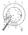
- the device shown consists essentially of a turntable 1, which forms a base 2 for the molds 3, which are uniformly distributed in a concentric circle on the turntable, and to which a stationary filling station 4 and, on the other hand, a stationary demolding station 5 are assigned, the demolding station 5 being the Filling station 4 is immediately upstream in the direction of rotation of the turntable 1.
- the turntable 1 has a self-supporting ring 6 which carries the base 2 for the molds 3 and is rotatably supported on stationary support rollers 7. To center the ring 6 are guide rollers 8 which are attached to the inner circumferential surface 9 of the ring 6 are made by springs or cylinders, which are not shown for reasons of clarity.
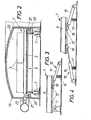
- a ring drive 10 is used to drive the ring 6, which, as shown in FIGS. 1 and 3, consists of a drive cylinder 11 acting in the direction of rotation, which is supported in a stationary manner and has a gripping head 13 which engages with drivers 12 along the ring 6.
- this gripping head 13 consists of a ring which includes the drivers 12, so that the ring 6 can not only be driven but also braked via the drive cylinder 11. So that the gripping head 13 can be plugged onto the driver 12, the drive cylinder 11 is pressed against the driver 12 via a spring 14, which press the gripping head 13 down for coupling against the force of the spring 14. To uncouple the gripping head 13 must be removed from the drivers 12, which is carried out by a separate device, which is not shown in detail. When the drive cylinder 11 is acted upon appropriately, the ring 6 is rotated via the gripper head 13, which holds one of the drivers 12, in accordance with the stroke of the drive cylinder 11.
- the gripping head 13 is to be removed from the driver 12 and the drive cylinder 11 is returned to its starting position, the gripping head 13 being plugged onto the following driver 12, so that a further turning step of the ring 6 is carried out when the cylinder 11 is loaded again can.
- a locking device can ensure the rotationally fixed mounting of the ring 6 during the resetting of the drive cylinder 11.
- a stepper drive 10 can be used with at least two cylinders 15 and 16 acting in opposite directions on the drivers 12, one of which serves as a drive cylinder and the other as a brake cylinder.
- the coupling of the cylinders 15 and 16 with the drivers 12 is made possible by springs 17 which press the print heads 18 of these cylinders against the drivers.
- To decouple the brake cylinder 16 its print head 18 must be lifted off the driver 12 again. This is not necessary for the drive cylinder 15 because the drivers 12 can reset the print head 18 against the force of the spring 17.
- the ring 6 of the turntable 1 is covered with a heat-insulating ring hood 19, which allows the ring surface of the turntable to be divided economically into several treatment zones, for example a storage zone, a preheating zone, a heating zone, a warming zone and a cooling zone .
- the seal between the driven ring 6 and the fixed ring hood 19 takes place via liquid-filled ring channels 20 which are provided on the ring hood 19 and protrude into the sealing webs 21.
- the resulting annular space 22 above the ring 6 can be charged with hot air, steam or cooling air via appropriate nozzles 23 in order to ensure the appropriate treatment of the shaped blocks.
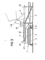
- the filling station 4 has a belt conveyor 25 which can be moved radially in a frame 24 and which carries at its discharge end 26 a scraper 27 which can be swiveled onto the molds 3.
- the foam concrete to be filled which is prepared in a mixing system 28, is fed via a chute 29 to a container 30 which is pivotally mounted on the frame 24 above the belt conveyor 25, so that the foam concrete is applied from the container 30 to the belt conveyor 25 can be.
- the belt conveyor 25 is then pulled back during operation from the outside inwards over the mold located in its area, the mold being filled with foam concrete.
- the scraper 27 pivoted onto the upper mold edge smoothes the filling and conveys the wiped material to a slide or the like in order to be able to feed it back to the new mold.
- the shaped stones in the molds are hardened to a degree that allows demolding.
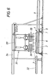
- the molds 3 are removed from the demolding station 5 with the aid of a lifting device 31 from that formed by the ring 6.
- Base 2 is lifted off and guided to a radial conveyor 32 on which the demolded shaped blocks are transported away.
- the trolley 33 of the hoist 31 which is mounted so as to be radially movable on a frame 34 bridging the ring 6, additionally carries an ejector 35 in the form of a plurality of ejection arms 36, by lifting the mold 3 over the ejector 35 with the aid of the hoist 31 the shaped stone can be pressed out of the mold, without additional lifting of the shaped stone, so that the drop height can advantageously remain low.
- the molds are lifted above the ejector 35, the mold can be cleaned in one operation if corresponding cleaning brushes or the like are arranged downstream of the ejection arms 36. After such cleaning, the mold can be sprayed with a release agent before it is placed on the turntable 1 again with the lifting device.
- the mold 3 prepared for a new filling reaches the area of the belt conveyor 25 of the filling station 4, at least during the next turning steps of the turntable, where it is again filled with foam concrete for the production of a further shaped block while repeating the working steps.
Landscapes
- Engineering & Computer Science (AREA)
- Mechanical Engineering (AREA)
- Manufacturing & Machinery (AREA)
- Chemical & Material Sciences (AREA)
- Ceramic Engineering (AREA)
- Devices For Post-Treatments, Processing, Supply, Discharge, And Other Processes (AREA)
- Cultivation Of Plants (AREA)
- Moulds, Cores, Or Mandrels (AREA)
- Moulds For Moulding Plastics Or The Like (AREA)
Applications Claiming Priority (2)
| Application Number | Priority Date | Filing Date | Title |
|---|---|---|---|
| AT161/84 | 1984-01-19 | ||
| AT16184A AT391102B (de) | 1984-01-19 | 1984-01-19 | Anlage zum herstellen von formsteinen aus schaumbeton |
Publications (3)
| Publication Number | Publication Date |
|---|---|
| EP0151379A2 true EP0151379A2 (fr) | 1985-08-14 |
| EP0151379A3 EP0151379A3 (en) | 1987-01-07 |
| EP0151379B1 EP0151379B1 (fr) | 1990-04-04 |
Family
ID=3483172
Family Applications (1)
| Application Number | Title | Priority Date | Filing Date |
|---|---|---|---|
| EP19840890239 Expired - Lifetime EP0151379B1 (fr) | 1984-01-19 | 1984-12-12 | Installation pour la fabrication de briques moulées en béton aéré |
Country Status (7)
| Country | Link |
|---|---|
| EP (1) | EP0151379B1 (fr) |
| AT (1) | AT391102B (fr) |
| DE (1) | DE3481830D1 (fr) |
| DK (1) | DK23685A (fr) |
| ES (1) | ES8601005A1 (fr) |
| FI (1) | FI76953C (fr) |
| NO (1) | NO161424C (fr) |
Cited By (4)
| Publication number | Priority date | Publication date | Assignee | Title |
|---|---|---|---|---|
| CN106584650A (zh) * | 2016-12-19 | 2017-04-26 | 淮安莱福模具科技有限公司 | 一种异向脱模砖模具 |
| CN108437163A (zh) * | 2018-04-03 | 2018-08-24 | 浙江水利水电学院 | 一种全自动均匀填料砂基透水砖生产设备 |
| CN116161524A (zh) * | 2023-03-03 | 2023-05-26 | 中建三局集团(深圳)有限公司 | 一种用于加砌块的智能化吊装设备 |
| CN119260898A (zh) * | 2024-12-06 | 2025-01-07 | 山西盛达威科技有限公司 | 一种负极石墨保温碳砖用原料加工用挤压成型装置 |
Families Citing this family (1)
| Publication number | Priority date | Publication date | Assignee | Title |
|---|---|---|---|---|
| CN102756424A (zh) * | 2012-06-19 | 2012-10-31 | 张大山 | 推挤式混凝土水泥杆异型成型机 |
Family Cites Families (9)
| Publication number | Priority date | Publication date | Assignee | Title |
|---|---|---|---|---|
| NL99889C (fr) * | 1900-01-01 | |||
| GB205679A (en) * | 1922-10-18 | 1923-10-25 | James William Wood | Improved apparatus for moulding concrete and other plastic substances |
| GB492280A (en) * | 1936-04-02 | 1938-09-16 | William Porter Witherow | Improvements in or relating to a method of and apparatus for making expanded cement articles |
| FR925338A (fr) * | 1945-04-10 | 1947-09-01 | Electro Refractaire | Produits réfractaires fondus |
| FR915338A (fr) * | 1945-05-11 | 1946-11-04 | Machine pour la fabrication d'agglomérés en série | |
| FR1144188A (fr) * | 1955-07-01 | 1957-10-10 | Afma | Procédé de fabrication de produits céramiques, installation et appareils pour sa mise en produits et produits obtenus |
| AT263598B (de) * | 1966-06-08 | 1968-07-25 | Walter Lanz | Verfahren und Einrichtung zur mechanisierten Herstellung von Hohlsteinen aus Gasbeton |
| DE2166391A1 (de) * | 1971-11-29 | 1974-02-21 | Beckmann Fa Bernhard | Muellsackdrehtisch |
| US3745856A (en) * | 1972-02-29 | 1973-07-17 | Resources Control Corp | Carousel indexing system for solid waste compactor |
-
1984
- 1984-01-19 AT AT16184A patent/AT391102B/de not_active IP Right Cessation
- 1984-12-12 EP EP19840890239 patent/EP0151379B1/fr not_active Expired - Lifetime
- 1984-12-12 DE DE8484890239T patent/DE3481830D1/de not_active Expired - Lifetime
-
1985
- 1985-01-16 FI FI850187A patent/FI76953C/fi not_active IP Right Cessation
- 1985-01-18 ES ES539693A patent/ES8601005A1/es not_active Expired
- 1985-01-18 NO NO850238A patent/NO161424C/no unknown
- 1985-01-18 DK DK23685A patent/DK23685A/da not_active Application Discontinuation
Cited By (4)
| Publication number | Priority date | Publication date | Assignee | Title |
|---|---|---|---|---|
| CN106584650A (zh) * | 2016-12-19 | 2017-04-26 | 淮安莱福模具科技有限公司 | 一种异向脱模砖模具 |
| CN108437163A (zh) * | 2018-04-03 | 2018-08-24 | 浙江水利水电学院 | 一种全自动均匀填料砂基透水砖生产设备 |
| CN116161524A (zh) * | 2023-03-03 | 2023-05-26 | 中建三局集团(深圳)有限公司 | 一种用于加砌块的智能化吊装设备 |
| CN119260898A (zh) * | 2024-12-06 | 2025-01-07 | 山西盛达威科技有限公司 | 一种负极石墨保温碳砖用原料加工用挤压成型装置 |
Also Published As
| Publication number | Publication date |
|---|---|
| EP0151379A3 (en) | 1987-01-07 |
| DK23685A (da) | 1985-07-20 |
| FI76953B (fi) | 1988-09-30 |
| AT391102B (de) | 1990-08-27 |
| ES539693A0 (es) | 1985-11-01 |
| NO850238L (no) | 1985-07-22 |
| ATA16184A (de) | 1990-02-15 |
| FI850187L (fi) | 1985-07-20 |
| EP0151379B1 (fr) | 1990-04-04 |
| NO161424C (no) | 1989-08-16 |
| ES8601005A1 (es) | 1985-11-01 |
| DK23685D0 (da) | 1985-01-18 |
| FI76953C (fi) | 1989-01-10 |
| NO161424B (no) | 1989-05-08 |
| DE3481830D1 (de) | 1990-05-10 |
| FI850187A0 (fi) | 1985-01-16 |
Similar Documents
| Publication | Publication Date | Title |
|---|---|---|
| DE2814715C3 (de) | Rotierende, kontinuierlich arbeitende Formvorrichtung für Gießkerne | |
| DE69738589T2 (de) | Verfahren zum Pressen von pulverförmigen Material | |
| EP0753387A1 (fr) | Procédé pour la fabrication de blocs de construction moulés | |
| DE1198015B (de) | Vollautomatisch arbeitende Drehtischformmaschine zum Herstellen von Sandformen fuer Giessereizwecke | |
| DE69309258T2 (de) | Vorrichtung zum Formen und Verfestigen von Käsen, insbesondere Pasta-Filata-Käse | |
| DE900189C (de) | Vorrichtung und Giessform zum Schneiden von halbplastischen Koerpern, insbesondere Leichtbetonkoerpern | |
| EP0649715A1 (fr) | Dispositif de fabrication de produits en béton de forme annulaire ou tubulaire | |
| AT391102B (de) | Anlage zum herstellen von formsteinen aus schaumbeton | |
| DE1265350B (de) | Blasmaschinen zum Herstellen von Giessereiformen und -kernen | |
| EP0496077A1 (fr) | Dispositif pour la fabrication de pierres | |
| DE2721874C2 (de) | Gießereiformmaschine | |
| DE3616949A1 (de) | Maschine zum formen und haerten von kaese | |
| DE2038577A1 (de) | Verfahren und Vorrichtung zum Herstellen harzgebundener Gusskerne | |
| DE3429601C3 (de) | Verfahren und Vorrichtung zur Herstellung von hohlzylindrischen Körpern aus Beton, insbesondere Palisadensteinen | |
| EP0415435B1 (fr) | Dispositif de fabrication de blocs en béton imitant les pierres naturelles | |
| DE2144388A1 (de) | Verfahren und Vorrichtung zur Herstellung von Gießformen | |
| DE2548894C2 (de) | Verfahren und Vorrichtung zum Herstellen von Elementen aus Porenbeton | |
| DE807259C (de) | Verfahren und Vorrichtung zur Massenherstellung von Betonwaren | |
| DE941426C (de) | Verfahren und Vorrichtung zur Gewinnung stueckiger Produkte aus nichtmetallischen Schmelzen | |
| DE2822028A1 (de) | Anlage zum herstellen von giessformhaelften in formkasten | |
| DE3704881C2 (fr) | ||
| DE520299C (de) | Maschine zur Herstellung mehrfarbiger Fliesen o. dgl. | |
| DE2059455A1 (de) | Vorrichtung zur Herstellung von Platten aus Beton u.dgl. | |
| DE534876C (de) | Fahrbare Stampfmaschine zum Herstellen von Betonholhlsteinen | |
| DE2307031C3 (de) | Anlage zum Herstellen von Baukörpern aus Porenbeton |
Legal Events
| Date | Code | Title | Description |
|---|---|---|---|
| PUAI | Public reference made under article 153(3) epc to a published international application that has entered the european phase |
Free format text: ORIGINAL CODE: 0009012 |
|
| AK | Designated contracting states |
Designated state(s): BE DE FR GB IT NL SE |
|
| PUAL | Search report despatched |
Free format text: ORIGINAL CODE: 0009013 |
|
| AK | Designated contracting states |
Kind code of ref document: A3 Designated state(s): BE DE FR GB IT NL SE |
|
| 17P | Request for examination filed |
Effective date: 19870304 |
|
| 17Q | First examination report despatched |
Effective date: 19890116 |
|
| RAP1 | Party data changed (applicant data changed or rights of an application transferred) |
Owner name: VOEST-ALPINE INDUSTRIEANLAGENBAU GESELLSCHAFT M B. |
|
| GRAA | (expected) grant |
Free format text: ORIGINAL CODE: 0009210 |
|
| AK | Designated contracting states |
Kind code of ref document: B1 Designated state(s): BE DE FR GB IT NL SE |
|
| PG25 | Lapsed in a contracting state [announced via postgrant information from national office to epo] |
Ref country code: NL Effective date: 19900404 Ref country code: BE Effective date: 19900404 |
|
| ITF | It: translation for a ep patent filed | ||
| REF | Corresponds to: |
Ref document number: 3481830 Country of ref document: DE Date of ref document: 19900510 |
|
| GBT | Gb: translation of ep patent filed (gb section 77(6)(a)/1977) | ||
| ET | Fr: translation filed | ||
| NLV1 | Nl: lapsed or annulled due to failure to fulfill the requirements of art. 29p and 29m of the patents act | ||
| PG25 | Lapsed in a contracting state [announced via postgrant information from national office to epo] |
Ref country code: GB Effective date: 19901212 |
|
| PG25 | Lapsed in a contracting state [announced via postgrant information from national office to epo] |
Ref country code: SE Effective date: 19901213 |
|
| PLBE | No opposition filed within time limit |
Free format text: ORIGINAL CODE: 0009261 |
|
| STAA | Information on the status of an ep patent application or granted ep patent |
Free format text: STATUS: NO OPPOSITION FILED WITHIN TIME LIMIT |
|
| 26N | No opposition filed | ||
| GBPC | Gb: european patent ceased through non-payment of renewal fee | ||
| PG25 | Lapsed in a contracting state [announced via postgrant information from national office to epo] |
Ref country code: FR Effective date: 19910830 |
|
| PG25 | Lapsed in a contracting state [announced via postgrant information from national office to epo] |
Ref country code: DE Effective date: 19910903 |
|
| REG | Reference to a national code |
Ref country code: FR Ref legal event code: ST |
|
| EUG | Se: european patent has lapsed |
Ref document number: 84890239.1 Effective date: 19910704 |