EP0151384A2 - Outil de tournage d'une pièce cylindrique - Google Patents
Outil de tournage d'une pièce cylindrique Download PDFInfo
- Publication number
- EP0151384A2 EP0151384A2 EP85100053A EP85100053A EP0151384A2 EP 0151384 A2 EP0151384 A2 EP 0151384A2 EP 85100053 A EP85100053 A EP 85100053A EP 85100053 A EP85100053 A EP 85100053A EP 0151384 A2 EP0151384 A2 EP 0151384A2
- Authority
- EP
- European Patent Office
- Prior art keywords
- tool
- tool according
- turning
- cutter head
- head part
- Prior art date
- Legal status (The legal status is an assumption and is not a legal conclusion. Google has not performed a legal analysis and makes no representation as to the accuracy of the status listed.)
- Withdrawn
Links
Images
Classifications
-
- B—PERFORMING OPERATIONS; TRANSPORTING
- B23—MACHINE TOOLS; METAL-WORKING NOT OTHERWISE PROVIDED FOR
- B23B—TURNING; BORING
- B23B29/00—Holders for non-rotary cutting tools; Boring bars or boring heads; Accessories for tool holders
- B23B29/24—Tool holders for a plurality of cutting tools, e.g. turrets
- B23B29/26—Tool holders in fixed position
Definitions
- the present invention relates to a tool for turning a cylindrical workpiece.
- the invention relates to a tool for turning off a thickened shaft part and / or a welding bead of a bolt welded to a surface.
- the present invention is based on the object of developing this known tool in such a way that it can be easily adapted to different machining tasks, in particular different bolt dimensions.
- the tool according to the invention can be produced very simply and inexpensively by the fact that it consists of only three simple parts, namely a holder part with a clamping device, a tubular connecting part and a cutter head part, and different due to the modular principle, namely the use of holder parts with differently designed clamping devices Adapt long tubular connecting parts and knife head parts with graduated peeling diameters to the respective application.
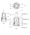
- the twisting or peeling tool shown in the drawing consists essentially of three parts, namely a holding part 10, a connecting pipe or part 12 and a cutter head part 14.
- the three parts 10, 12 and 14 are connected to each other by screwing.
- the holding part 10 forms a clamping pin 16 for clamping in a chuck of a drilling machine, an annular flange part 18 and a threaded pin 20 with an external thread.
- the connecting tube 12 has the shape of a hollow cylinder and is provided with an internal thread 22 and 24 at the ends. It also has two pairs of diametrically opposed radial holes 26.
- the cutter head 14 has a bush-shaped upper end 28 with an external thread and a lower end of enlarged diameter, which forms holders for turning tools 30.
- the brackets consist of slots 32 which run radially and in the manner shown in FIG. 2 obliquely to the axis of rotation 34.
- the turning tools 30 are in these mounting slots 32 of the cutter head part Les directly fastened by clamping screws 36 (ie not via their own tool holder and insert holder, as with the tool according to DE-U-81 20 797 mentioned above).
- brackets are provided for four turning tools with mutual angular distances of 90 degrees.
- the cutter head 14 forms a central axial recess 38 for receiving the workpiece to be turned. As can be seen from FIG.
- the cutting edges of the turning tools 30 protrude into this recess.
- the cutting edges of the turning tools each have a rounded front end, to the outside of which a cutting part that runs obliquely to the rear and the inside are connected to a surface that runs essentially parallel to the axis of rotation of the tool and is preferably set back slightly (a few tenths of a millimeter). These surfaces lie on the workpiece without cutting and thus contribute to the self-centering of the tool with respect to the workpiece.
- the threaded pin 20 and the threaded end 28 are screwed into the connecting tube 12, as can be seen from FIG. 2.
- a set of connecting tubes of different lengths and a set of cutter heads with stepped diameters of the recess 38 and / or the radial spacing of the cutting edges of the turning tools 30 are provided.
- the tool can then be used for a wide variety of purposes by selecting a connecting tube 12 and a cutter head 14 which are adapted to the respective task.
- the assembly and disassembly can, if necessary, be effected quickly with the aid of a rod inserted through the openings 26, so that only short set-up times are required.
- the clamping device 16 'of the first part can also have an inner chuck cone 19 for a standardized clamping cone mandrel of a drilling machine.
Landscapes
- Engineering & Computer Science (AREA)
- Mechanical Engineering (AREA)
- Drilling Tools (AREA)
- Turning (AREA)
- Cutting Tools, Boring Holders, And Turrets (AREA)
Applications Claiming Priority (2)
| Application Number | Priority Date | Filing Date | Title |
|---|---|---|---|
| DE19843404643 DE3404643A1 (de) | 1984-02-09 | 1984-02-09 | Werkzeug zum abdrehen eines zylindrischen werkstuecks |
| DE3404643 | 1984-02-09 |
Publications (2)
| Publication Number | Publication Date |
|---|---|
| EP0151384A2 true EP0151384A2 (fr) | 1985-08-14 |
| EP0151384A3 EP0151384A3 (fr) | 1987-07-15 |
Family
ID=6227272
Family Applications (1)
| Application Number | Title | Priority Date | Filing Date |
|---|---|---|---|
| EP85100053A Withdrawn EP0151384A3 (fr) | 1984-02-09 | 1985-01-02 | Outil de tournage d'une pièce cylindrique |
Country Status (2)
| Country | Link |
|---|---|
| EP (1) | EP0151384A3 (fr) |
| DE (1) | DE3404643A1 (fr) |
Cited By (2)
| Publication number | Priority date | Publication date | Assignee | Title |
|---|---|---|---|---|
| US5733075A (en) * | 1993-07-06 | 1998-03-31 | Basteck; Andreas | Machining device |
| RU200532U1 (ru) * | 2020-06-25 | 2020-10-28 | федеральное государственное бюджетное образовательное учреждение высшего образования «Донской государственный технический университет» (ДГТУ) | Устройство для токарной обработки длинномерных нежестких валов |
Family Cites Families (7)
| Publication number | Priority date | Publication date | Assignee | Title |
|---|---|---|---|---|
| DE167997C (fr) * | ||||
| DE275864C (fr) * | ||||
| US2816769A (en) * | 1955-07-22 | 1957-12-17 | Richard M Noble | Drill bit extension |
| CH427713A (de) * | 1965-04-01 | 1967-01-15 | Fischer Ag Georg | Entgratungswerkzeug für Rohre |
| CH537770A (de) * | 1971-05-03 | 1973-06-15 | Kaiser Heinz | Ausdrehwerkzeug |
| DE8120797U1 (de) * | 1981-07-16 | 1982-12-30 | Komet Stahlhalter- Und Werkzeugfabrik Robert Breuning Gmbh, 7122 Besigheim | Drehwerkzeug fuer die endenbearbeitung von wellen, zapfen, rohren u.dgl. |
| DE3131055C2 (de) * | 1981-08-05 | 1983-05-26 | Max Planck Gesellschaft zur Förderung der Wissenschaften e.V., 3400 Göttingen | Verfahren und Vorrichtung zum Bolzenschweißen |
-
1984
- 1984-02-09 DE DE19843404643 patent/DE3404643A1/de not_active Withdrawn
-
1985
- 1985-01-02 EP EP85100053A patent/EP0151384A3/fr not_active Withdrawn
Cited By (2)
| Publication number | Priority date | Publication date | Assignee | Title |
|---|---|---|---|---|
| US5733075A (en) * | 1993-07-06 | 1998-03-31 | Basteck; Andreas | Machining device |
| RU200532U1 (ru) * | 2020-06-25 | 2020-10-28 | федеральное государственное бюджетное образовательное учреждение высшего образования «Донской государственный технический университет» (ДГТУ) | Устройство для токарной обработки длинномерных нежестких валов |
Also Published As
| Publication number | Publication date |
|---|---|
| EP0151384A3 (fr) | 1987-07-15 |
| DE3404643A1 (de) | 1985-08-14 |
Similar Documents
| Publication | Publication Date | Title |
|---|---|---|
| EP0687516B1 (fr) | Outil combiné | |
| EP1932607B1 (fr) | Support de pièce à usiner destiné à la fixation exacte sur un mandrin ainsi que dispositif à mandrin doté d'un mandrin et d'un support de pièce à usiner fixé fermement et positionné exactement sur celui-ci | |
| EP0215283B1 (fr) | Accouplement d'outil | |
| EP0141451B1 (fr) | Dispositif de fixation d'outil et porte-outil | |
| EP1602427A1 (fr) | Dispositif de serrage avec un mandrin et sa pince détachable | |
| CH663562A5 (de) | Kupplungsvorrichtung fuer modulare werkzeugsysteme. | |
| EP0158182A2 (fr) | Tête à fraiser et percer pour une machine-outil | |
| DE10219600B4 (de) | Werkzeugträger mit einer Spannzangenaufnahme | |
| CH656080A5 (de) | Drehwerkzeug fuer die endenbearbeitung von wellen, zapfen, rohren. | |
| DE102013215258A1 (de) | Modulares schaftwerkzeug | |
| DE3706123C2 (fr) | ||
| DE4021090A1 (de) | Bearbeitungsvorrichtung mit mitteln zur aenderung der radialen position von schneidwerkzeugen | |
| DE3128121C2 (de) | Drehwerkzeug für die Endenbearbeitung von Wellen, Zapfen, Rohren und dergleichen | |
| EP0523574A2 (fr) | Dispositif de serrage pour outils singuliers | |
| DE20319597U1 (de) | Werkzeughalter-System | |
| EP0363456B1 (fr) | Outil, notamment outil d'alesage ou similaire | |
| DE4008350C2 (de) | Modular aufgebautes Schaftwerkzeug für die Innen- und/oder Außenbearbeitung von Werkstückoberflächen | |
| DE8428715U1 (de) | Vorrichtung zum Einspannen und Zentrieren von Rohren an der Reitstockseite von Drehbänken | |
| EP0151384A2 (fr) | Outil de tournage d'une pièce cylindrique | |
| EP2254715B1 (fr) | Outil | |
| DE4121495C1 (en) | Machine for workpiece bore machining - has elongated tubular sleeve for drill spindle, retaining latter support bearing | |
| DE202006007258U1 (de) | Werkzeug zum Bearbeiten eines Rohrendes | |
| DE19736741A1 (de) | Einstellvorrichtung | |
| DE29713050U1 (de) | Werkzeug zum Bearbeiten eines Kunststoff-Rohres | |
| AT409353B (de) | Fräswerkzeug |
Legal Events
| Date | Code | Title | Description |
|---|---|---|---|
| PUAI | Public reference made under article 153(3) epc to a published international application that has entered the european phase |
Free format text: ORIGINAL CODE: 0009012 |
|
| AK | Designated contracting states |
Designated state(s): CH DE FR GB IT LI NL |
|
| PUAL | Search report despatched |
Free format text: ORIGINAL CODE: 0009013 |
|
| AK | Designated contracting states |
Kind code of ref document: A3 Designated state(s): CH DE FR GB IT LI NL |
|
| 17P | Request for examination filed |
Effective date: 19870701 |
|
| 17Q | First examination report despatched |
Effective date: 19871002 |
|
| STAA | Information on the status of an ep patent application or granted ep patent |
Free format text: STATUS: THE APPLICATION IS DEEMED TO BE WITHDRAWN |
|
| 18D | Application deemed to be withdrawn |
Effective date: 19890606 |
|
| RIN1 | Information on inventor provided before grant (corrected) |
Inventor name: KOTZLOWSKI, HEINZ ERNST |