EP0151407B1 - Laderantrieb für aufgeladenen Verbrennungsmotor - Google Patents
Laderantrieb für aufgeladenen Verbrennungsmotor Download PDFInfo
- Publication number
- EP0151407B1 EP0151407B1 EP19850100382 EP85100382A EP0151407B1 EP 0151407 B1 EP0151407 B1 EP 0151407B1 EP 19850100382 EP19850100382 EP 19850100382 EP 85100382 A EP85100382 A EP 85100382A EP 0151407 B1 EP0151407 B1 EP 0151407B1
- Authority
- EP
- European Patent Office
- Prior art keywords
- engine
- exhaust gas
- rotor
- speed
- ratio
- Prior art date
- Legal status (The legal status is an assumption and is not a legal conclusion. Google has not performed a legal analysis and makes no representation as to the accuracy of the status listed.)
- Expired
Links
- 238000002485 combustion reaction Methods 0.000 title description 7
- 230000003247 decreasing effect Effects 0.000 claims description 10
- 230000000694 effects Effects 0.000 description 11
- 230000006835 compression Effects 0.000 description 3
- 238000007906 compression Methods 0.000 description 3
- 230000004323 axial length Effects 0.000 description 1
- 230000001419 dependent effect Effects 0.000 description 1
- 238000010586 diagram Methods 0.000 description 1
- 239000000446 fuel Substances 0.000 description 1
- 230000000644 propagated effect Effects 0.000 description 1
Images

Classifications
-
- F—MECHANICAL ENGINEERING; LIGHTING; HEATING; WEAPONS; BLASTING
- F04—POSITIVE - DISPLACEMENT MACHINES FOR LIQUIDS; PUMPS FOR LIQUIDS OR ELASTIC FLUIDS
- F04F—PUMPING OF FLUID BY DIRECT CONTACT OF ANOTHER FLUID OR BY USING INERTIA OF FLUID TO BE PUMPED; SIPHONS
- F04F13/00—Pressure exchangers
-
- F—MECHANICAL ENGINEERING; LIGHTING; HEATING; WEAPONS; BLASTING
- F02—COMBUSTION ENGINES; HOT-GAS OR COMBUSTION-PRODUCT ENGINE PLANTS
- F02B—INTERNAL-COMBUSTION PISTON ENGINES; COMBUSTION ENGINES IN GENERAL
- F02B33/00—Engines characterised by provision of pumps for charging or scavenging
- F02B33/32—Engines with pumps other than of reciprocating-piston type
- F02B33/42—Engines with pumps other than of reciprocating-piston type with driven apparatus for immediate conversion of combustion gas pressure into pressure of fresh charge, e.g. with cell-type pressure exchangers
-
- F—MECHANICAL ENGINEERING; LIGHTING; HEATING; WEAPONS; BLASTING
- F02—COMBUSTION ENGINES; HOT-GAS OR COMBUSTION-PRODUCT ENGINE PLANTS
- F02B—INTERNAL-COMBUSTION PISTON ENGINES; COMBUSTION ENGINES IN GENERAL
- F02B39/00—Component parts, details, or accessories relating to, driven charging or scavenging pumps, not provided for in groups F02B33/00 - F02B37/00
- F02B39/02—Drives of pumps; Varying pump drive gear ratio
- F02B39/08—Non-mechanical drives, e.g. fluid drives having variable gear ratio
- F02B39/10—Non-mechanical drives, e.g. fluid drives having variable gear ratio electric
Definitions
- the present invention relates to a supercharged engine, and more particularly to an engine having a suchercharger of a type in which the intake air is compressed by the pressure of the exhaust gas before it is introduced into the combustion chamber.
- a supercharger of this type generally includes a rotor having a plurality of mutually separated, axially extending gas passages and a casing supporting the rotor for rotation about an axis of rotation.
- the casing is provided with exhaust gas inlet and outlet openings and intake gas inlet and outlet openings which are located to oppose to axial ends of the rotor. The arrangements are such that the intake air is drawing into the gas passages through the intake gas inlet opening and compressed by the pressure of the exhaust gas introduced into the gas passages through the exhaust gas inlet opening.
- the gas passages are sequentially opened to the intake gas outlet opening so that the intake gas is forced by the exhaust gas to flow into the intake passage communicating with the intake gas outlet opening. Thereafter, the passages are opened to the exhaust gas outlet opening so that the exhaust gas is allowed to flow into the exhaust passage communicating with the exhaust gas outlet opening.
- the exhaust gas inlet opening and the intake gas outlet opening be located axially opposite to each other with respect to the rotor.
- An example of such supercharger is disclosed by Japanese utility model disclosure No. 55-127839.
- the supercharger disclosed by the utility model is of a type wherein the exhaust gas inlet and outlet openings are located at one axial end of the rotor and the intake gas inlet and outlet openings are located at the other axial end so that the exhaust gas and the intake gas change their flow directions in the gas passages.
- the gas inlet and outlet openings are arranged so that the exhaust gas and the intake gas flow axially through the gas passages without changing the flow directions.
- the supercharger of the aforementioned type is considered as being particularly suitable for diesel cycle engines but can of course be used in gasoline engines as well.
- the characteristic features of the supercharger of this type are not only that a supercharging effect can be obtained even in a low speed engine operation but also that an exhaust gas recirculation effect can be obtained because the exhaust gas is brought into contact with the intake gas in the rotor.
- the rotor since the rotor is driven in synchronism with the engine rotation, it is impossible to control the amount of recirculated exhaust gas in a desired manner. For example, if the rotating speed of the rotor is determined so that a desirable exhaust gas recirculation is accomplished in a low and medium speed operations, there will be an output loss under a high speed, heavy load operation due to a decrease in the intake charge.
- Another object of the present invention is to provide a supercharger of the aforementioned type which can prevent the exhaust gas from being mixed with the intake air under a heavy load operation so that a high engine output can be obtained.
- a further object of the present invention is to provide an engine supercharger which is effective to prevent misfire under a low temperature, light load engine operation.
- Still further object of the present invention is to provide a supercharger which can present an exhaust gas brake effect.
- a supercharged engine including a supercharger comprising a rotor having an axis of rotation and formed with a plurality of mutually separated, axially extending gas passages and a casing supporting the rotor for rotation about the axis of rotation.
- the casing is formed with exhaust gas inlet port means opposing to an end of the rotor and exhaust outlet port means opposing to the same or opposite end of the rotor.
- the exhaust gas outlet port means is offset with respect to the exhaust gas inlet port means in the direction of rotor rotation.
- the exhaust gas inlet port means is connected with exhaust port means of the engine whereas the exhaust gas outlet port means is opened to the atmosphere.
- the casing is further formed, at an end of the rotor opposite to the end where the exhaust gas inlet port means is formed, with intake gas outlet means which is connected with intake port means of the engine and, at an end of the rotor opposite to the end where the exhaust gas outlet port means is formed, with intake gas inlet port means for drawing the intake gas.
- an electric motor is provided for driving the rotor and the motor is controlled by a control unit in accordance with the engine operating condition so that a ratio of the rotor speed to the engine speed is changed in accordance with the engine operating condition.
- the aforementioned ratio is increased under a heavy load operation of the engine.
- the ratio is decreased under a low temperature, light load engine operation.
- the ratio is decreased in deceleration.
- the gas passages in the rotor are sequentially opened to the exhaust gas inlet port means so as to be subjected to the exhaust gas pressure and the pressure is transmitted at a sonic speed through the gas passages. Therefore, by appropriately determining the relative locations of the exhaust gas inlet port means and the intake gas outlet port means, the axial lengths of the gas passages and other factors, it is possible to transmit the pressure at the exhaust gas inlet port means to the intake gas outlet port means producing a supercharging effect.
- the flow speed of the exhaust gas in the gas passages is slower than the propagation of the gas pressure so that it is unlikely that the exhaust gas in mixed with the intake air which is being introduced into the engine if the gas passage is disconnected from the intake gas outlet port means before the exhaust gas reaches the intake gas outlet port means.
- the rotor speed is controlled proportionally to the engine speed. If, however, the rotor speed is controlled, under an engine operating condition wherein an exhaust gas recirculation is desired, so that the rotor speed is decreased with respect to the engine speed, the exhaust gas can reach the intake gas outlet port means before the port means is closed producing an exhaust gas recirculation effect. It is possible to control the quantity of the exhaust gas recirculation by changing the ratio of the rotor speed to the engine speed. In an engine operating condition wherein the exhaust gas recirculation is undesirable, such as a high speed, heavy load engine operation, the exhaust gas recirculation can be prevented by increasing the aforementioned ratio.
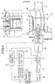
- the engine 1 includes a cylinder 2 and a cylinder head 3 attached to the top end portion of the cylinder 2.
- a piston 4 is disposed in the cylinder 2 for reciprocating movements and defines a combustion chamber 12 in the cylinder 2.
- the cylinder head 3 is formed with an intake port 5 and an exhaust port 6 which are respectively provided with an intake valve 7 and an exhaust valve 8.
- the intake port 5 is connected with a supercharging passage 9 whereas the exhaust port 6 is connected with an exhaust passage 10. Between the supercharging passage 9 and the exhaust passage 10, there is a supercharger 11.
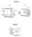
- the supercharger 11 includes a casing 14 shown in Figure 2 (a) and a rotor 15 shown in Figure 2 (b).
- the rotor 15 is rotatably disposed in the casing 14.
- the rotor 15 has a plurality of mutually separated, axially extending gas passages 16.
- the casing 14 has end walls 14a and 14b respectively opposing to the opposite ends of the rotor 15.
- the end wall 14a is formed with an exhaust gas inlet port 17 and an exhaust gas outlet port 18 which are circumferentialy offset from each other.
- the end wall 14b is formed with an intake gas inlet port 19 and an intake gas outlet port 20 at circumferentially offset portions.
- the exhaust gas inlet port 17 of the casing 14 is connected with the exhaust passage 10 and the intake gas outlet port 20 is connected with the supercharging passage 9,
- the exhaust gas outlet port 18 is connected with an exhaust pipe 21 whereas the intake gas inlet port 19 is connected with an intake pipe 22.
- the rotor 15 has a drive shaft 23 which is secured thereto and extending axially outwardly from one end of the rotor 15.
- the drive shaft 23 is rotatably supported through bearings 24 and 25 by an intake housing 26 to which the casing 14 is secured.
- the axial outer end of the drive shaft 23 is connected through an electromagnetic clutch 27 with the output shaft of an electric motor 28.
- a control unit 29 In order to control the operation of the motor 28, there is provided a control unit 29.
- the engine 1 is provided with an engine speed detector 30 and an engine control member position detector 32.
- the output of the engine speed detector 30 is applied to the control unit 29 and produces an output proportional to the engine speed.
- the control unit 29 produces an output pulse of which pulse frequency increases in proportion to an increase in the engine speed.
- the output of the control unit 29 is applied to a modifying circuit 31 which produces an output for operating the motor 28.
- the output of the engine control member position detector 32 is applied to the modifying circuit 31 which functions to modify the output of the control unit 29 in accordance with the output of the detector 32 which represents the engine load.
- the speed of the motor 28 is controlled in accordance with the engine speed and the engine load.
- a light load discriminating circuit 36 having inputs connected with a reference circuit 35 and an engine temperature detector 38, respectively.
- the discriminating circuit 36 further has an input connected with the engine control member position detector 32.
- the reference circuit 35 produces a reference voltage which is compared in the discriminating circuit with the position signal from the detector 32 to discrimate light load engine operating condition from the other operating conditions.
- the discriminating circuit 36 produces an output when the engine temperature is below a predetermined value under a light load engine operation. The output of the circuit 36 is applied to the modifying circuit 31.
- deceleration discriminating circuit 40 which has inputs connected with the engine speed detector 30 and the engine control member position detector 32, respectively.
- the discriminating circuit produces an engine deceleration signal when the engine control member is at the minimum output position but the engine speed is above a predetermined value.
- the engine 1 is started and the clutch 27 is engaged.
- the motor 28 is operated by the output of the modifying circuit 31 to drive the rotor 15.
- the intake air is drawn through the intake pipe 22 and the inlet port 19 into the gass passages in the rotor 15.
- the intake air in the gas passages 16 is then discharged to the supercharging passage 9 when the passages are opened to the outlet port 20 so that the intake air is charged to the combustion chamber 12.
- the exhaust gas from the engine exhaust port 6 is directed through the exhaust passage 10 and the inlet port 17 to the gas passages 16 in the rotor 15.
- the exhaust gas in then discharged to the exhaust pipe 21 through the outlet port 18 when the gas passages 16 are opened to the outlet port 18.
- the exhaust gas inlet port 17 is located axially opposite to the intake gas outlet port 20 so that the exhaust gas pressure in the exhaust passage 10 is applied to one end of the gas passage 16 when the gas passage 16 is opened to the inlet port 17.
- the pressure is then transmitted longitudinally through the passage 16 compressing the intake air in the passage 16 and reaches the other end of the passage 16 which is opened to the outlet port 20.
- the intake air is discharged into the supercharging passage 9 in a compressed condition.
- FIG 4 there are shown the gas passages 16 in the rotor 15 in extended positions.
- the uppermost passage 16a is shown as being filled by the intake air. Since the passage 16a is closed at the both ends, the air in the passage 16a is in a stationary condition.
- the adjacent passage 16b is in a more advanced phase and has one end opened to the exhaust gas inlet port 17 so that a compression wave is produced at the end as shown by the numeral 33.
- the exhaust gas is admitted to the passage 16b as shown by the numeral 34.
- the passages 16c and 16d which are more advanced in phase the compression waves are propagated as shown by the numerals 33a and 33b and the exhaust gas is admitted further deep in the passages as shown by the numerals 34a and 34b.
- passages 16c and 16d are still closed at the other ends so that the intake air in the vicinity of these ends is stationary.
- the other end is opened to the intake gas outlet port 20 and the compression wave has reached the outlet port 20.
- the intake air is discharged under a supercharged condition into the passage 9.
- the passages 16f, 16g and 16h the discharge of the intake air is still continued and the exhaust gas flows in the passages in the direction of the intake air flow.
- the passage 16i is disconnected from the exhaust gas inlet port 17 so that the flow of the exhaust gas is ceased at the end adjacent to the port 17 as shown by the numeral 34c.
- the passage 16j is disconnected from the intake gas outlet port 20 so that the flow in the passage is ceased.
- the passage 16k is opened at one end to the exhaust gas outlet port 18 so that the exhaust gas is expanded at this end as shown by the numeral 35. The expansion of the exhaust gas progresses as the phase advances.
- the other end is opened to the intake air inlet port 19 so that the intake air under the atmospheric pressure is admitted to the passage expelling the expanded exhaust gas into the exhaust pipe 21.
- FIG. 3 there is shown the relation between the amount of the exhaust gas admitted to the supercharging passage and the aforementioned ratio.
- the curve C shows the ratio of the rotor speed to the engine speed wherein the exhaust gas is not admitted to the passage 9. If the ratio is lower than the curve C, there will be a certain amount of exhaust gas flow into the passage 9 producing an exhaust gas recirculation effect.
- the amount of the recirculated exhaust gas is dependent on the difference between the curve C and the ratio. For example, if the ratio is changed as shown by the curve a in accordance with the amount of fuel supply, that is, the engine load, the amount of the recirculated exhaust gas changes as shown by the curve b.
- the exhaust gas recirculation is performed in the medium load operation to decrease NOx. Futher. under a heavy load operation the exhaust gas is prevented from entering the combustion chamber so that it is possible to suppress smokes which may otherwise be produced in diesel engines.
- heavy load region there will be an increase in the exhaust gas temperature which will cause an increase in the temperature of the supercharger.
- the fresh intake air flows through the gas passages 16 to the exhaust pipe in the heavy load region so that the supercharger is cooled by the fresh intake air.
- the ratio is maintained substantially constant or slightly decreased so as to make the loss of the intake air as small as possible. With this control, it becomes possible to ensure sufficient supercharging effect simultaneously preveating overheat of the supercharger.
- the discriminating circuit 36 In an cold engine operation wherein the engine temperature is below a predetermined value, the discriminating circuit 36 produces a light load signal when the engine load is below a predetermined value. This signal is applied to the modifying circuit 31 to decrease the ratio as shown by a curve d to thereby increase the amount of the recirculated exhaust gas as shown by a curve e. This will cause an increase in the intake air temperature so that misfire can effectively be prevented. Further, in a deceleration, the discriminating circuit 40 produces a deceleration signal which is applied to the modifying circuit 31 to decrease the aforementioned ratio. This will produce an exhaust gas brake effect as described previously.
- the electromagnetic clutch 27 may be controlled in accordance with the output of the engine control member position detector 32 so that the clutch 27 is disengaged when the engine load is below.a predetermined value. Since the exhaust passage 36.is inclined with respect to the axis of the rotor 15 in the direction of the rotor rotation, the rotor 15 is slowly rotated by the exhaust gas flow even when the clutch 27 is disengaged. With this control, the ratio of the rotor speed to the engine speed changes as shown by a line f in Figure 3.
Landscapes
- Engineering & Computer Science (AREA)
- Mechanical Engineering (AREA)
- General Engineering & Computer Science (AREA)
- Chemical & Material Sciences (AREA)
- Combustion & Propulsion (AREA)
- Supercharger (AREA)
Claims (9)
Applications Claiming Priority (8)
| Application Number | Priority Date | Filing Date | Title |
|---|---|---|---|
| JP681584A JPS60150428A (ja) | 1984-01-18 | 1984-01-18 | 過給機付エンジン |
| JP681484A JPS60150427A (ja) | 1984-01-18 | 1984-01-18 | 過給機付エンジン |
| JP6815/84 | 1984-01-18 | ||
| JP6814/84 | 1984-01-18 | ||
| JP1304884A JPS60159338A (ja) | 1984-01-27 | 1984-01-27 | 過給機付エンジン |
| JP13048/84 | 1984-01-27 | ||
| JP1565584A JPS60159339A (ja) | 1984-01-30 | 1984-01-30 | 過給機付エンジン |
| JP15655/84 | 1984-01-30 |
Publications (2)
| Publication Number | Publication Date |
|---|---|
| EP0151407A1 EP0151407A1 (de) | 1985-08-14 |
| EP0151407B1 true EP0151407B1 (de) | 1987-06-16 |
Family
ID=27454579
Family Applications (1)
| Application Number | Title | Priority Date | Filing Date |
|---|---|---|---|
| EP19850100382 Expired EP0151407B1 (de) | 1984-01-18 | 1985-01-16 | Laderantrieb für aufgeladenen Verbrennungsmotor |
Country Status (2)
| Country | Link |
|---|---|
| EP (1) | EP0151407B1 (de) |
| DE (1) | DE3560268D1 (de) |
Families Citing this family (10)
| Publication number | Priority date | Publication date | Assignee | Title |
|---|---|---|---|---|
| ATE70894T1 (de) * | 1986-10-29 | 1992-01-15 | Comprex Ag | Druckwellenlader. |
| EP0286931A1 (de) * | 1987-04-16 | 1988-10-19 | BBC Brown Boveri AG | Freilaufender Druckwellenlader |
| AT408785B (de) * | 1995-11-30 | 2002-03-25 | Blank Otto Ing | Aufladeeinrichtung für die ladeluft einer verbrennungskraftmaschine |
| US5724949A (en) * | 1996-11-06 | 1998-03-10 | Caterpillar Inc. | Hydraulic drive for a pressure wave supercharger utilized with an internal combustion engine |
| DE102004038440A1 (de) * | 2004-08-07 | 2006-03-16 | Ksb Aktiengesellschaft | Drehzahlregelbarer Druckaustauscher |
| FR2879250A1 (fr) * | 2004-12-09 | 2006-06-16 | Renault Sas | Dispositif de suralimentation d'air pour moteur a combustion interne avec recyclage de gaz d'echappement, et procede associe. |
| FR2879249A1 (fr) * | 2004-12-09 | 2006-06-16 | Renault Sas | Dispositif de suralimentation et de stratification de gaz d'echappement recycles pour moteur a combustion interne, notamment pour vehicule automobile, et procede associe. |
| DE102010008385A1 (de) * | 2010-02-17 | 2011-08-18 | Benteler Automobiltechnik GmbH, 33102 | Verfahren zur Einstellung eines Ladedruckes |
| DE102011053218B4 (de) * | 2011-09-02 | 2015-06-25 | Benteler Automobiltechnik Gmbh | Druckwellenladeranordnung mit elektromagnetischer Schlupfkupplung |
| AU2015243195B2 (en) * | 2014-04-10 | 2017-06-22 | Energy Recovery, Inc. | Pressure exchange system with motor system |
Family Cites Families (8)
| Publication number | Priority date | Publication date | Assignee | Title |
|---|---|---|---|---|
| US1428924A (en) * | 1920-06-29 | 1922-09-12 | Carl C Thomas | Supercharger for internal-combustion engines |
| FR753944A (de) * | 1932-04-07 | 1933-10-26 | ||
| CH242427A (de) * | 1943-06-05 | 1946-05-15 | Sulzer Ag | Verfahren zur Regelung der Förderleistung eines von einer Abgasturbine angetriebenen Verdichters und Einrichtung zur Durchführung des Verfahrens. |
| US3078034A (en) * | 1956-03-29 | 1963-02-19 | Spalding Dudley Brian | Pressure exchanger |
| US3076422A (en) * | 1958-09-19 | 1963-02-05 | Spalding Dudley Brian | Pressure exchangers |
| DE2206450A1 (de) * | 1972-02-11 | 1973-08-16 | Daimler Benz Ag | Verbrennungsmotor mit einem abgasturbolader |
| US4360317A (en) * | 1980-08-01 | 1982-11-23 | Ford Motor Company | Three cycle per revolution wave compression supercharger |
| FR2488330A1 (fr) * | 1980-08-11 | 1982-02-12 | Chauvierre Marc | Procede de suralimentation des moteurs a explosion a bas regime |
-
1985
- 1985-01-16 EP EP19850100382 patent/EP0151407B1/de not_active Expired
- 1985-01-16 DE DE8585100382T patent/DE3560268D1/de not_active Expired
Also Published As
| Publication number | Publication date |
|---|---|
| EP0151407A1 (de) | 1985-08-14 |
| DE3560268D1 (en) | 1987-07-23 |
Similar Documents
| Publication | Publication Date | Title |
|---|---|---|
| US4702218A (en) | Engine intake system having a pressure wave supercharger | |
| US4426985A (en) | Supercharged internal combustion engine | |
| US4506633A (en) | Internal combustion engine | |
| US5724813A (en) | Compressor by-pass and valving for a turbocharger | |
| US6182449B1 (en) | Charge air systems for two-cycle internal combustion engines | |
| US4350013A (en) | Exhaust gas recirculation system | |
| US4535592A (en) | Internal combustion engine having an exhaust gas turbine | |
| US6408832B1 (en) | Outboard motor with a charge air cooler | |
| GB2127895A (en) | I.c. engine turbocharger in series with a positive displacement blower | |
| EP0151407A1 (de) | Laderantrieb für aufgeladenen Verbrennungsmotor | |
| US4986780A (en) | Two cycle engine | |
| US4995347A (en) | Intake device of a two stroke engine with supercharger bypass passage | |
| US5080081A (en) | Four-cycle heat insulating engine | |
| US4776167A (en) | Turbo-supercharger for internal combustion engine | |
| US4718235A (en) | Turbo compound internal combustion engine | |
| US4911122A (en) | Tuned intake air inlet for a rotary engine | |
| JPS6349543Y2 (de) | ||
| JPH0275726A (ja) | 過給機付きディーゼル機関 | |
| CA2058121A1 (en) | Turbo-charged internal combustion engine | |
| JPH0442528B2 (de) | ||
| US4432206A (en) | Supercharged internal combustion engines, in particular diesel engines, and in methods for starting up and regulating the speed of these engines | |
| JPS609382Y2 (ja) | 排気タ−ボ過給機 | |
| JPH0536609B2 (de) | ||
| JPH0121132Y2 (de) | ||
| JPH0442529B2 (de) |
Legal Events
| Date | Code | Title | Description |
|---|---|---|---|
| PUAI | Public reference made under article 153(3) epc to a published international application that has entered the european phase |
Free format text: ORIGINAL CODE: 0009012 |
|
| 17P | Request for examination filed |
Effective date: 19850116 |
|
| AK | Designated contracting states |
Designated state(s): DE FR GB |
|
| 17Q | First examination report despatched |
Effective date: 19860904 |
|
| GRAA | (expected) grant |
Free format text: ORIGINAL CODE: 0009210 |
|
| AK | Designated contracting states |
Kind code of ref document: B1 Designated state(s): DE FR GB |
|
| REF | Corresponds to: |
Ref document number: 3560268 Country of ref document: DE Date of ref document: 19870723 |
|
| ET | Fr: translation filed | ||
| PLBE | No opposition filed within time limit |
Free format text: ORIGINAL CODE: 0009261 |
|
| STAA | Information on the status of an ep patent application or granted ep patent |
Free format text: STATUS: NO OPPOSITION FILED WITHIN TIME LIMIT |
|
| 26N | No opposition filed | ||
| PGFP | Annual fee paid to national office [announced via postgrant information from national office to epo] |
Ref country code: FR Payment date: 19931222 Year of fee payment: 10 |
|
| PGFP | Annual fee paid to national office [announced via postgrant information from national office to epo] |
Ref country code: GB Payment date: 19940106 Year of fee payment: 10 |
|
| PGFP | Annual fee paid to national office [announced via postgrant information from national office to epo] |
Ref country code: DE Payment date: 19940127 Year of fee payment: 10 |
|
| PG25 | Lapsed in a contracting state [announced via postgrant information from national office to epo] |
Ref country code: GB Effective date: 19950116 |
|
| GBPC | Gb: european patent ceased through non-payment of renewal fee |
Effective date: 19950116 |
|
| PG25 | Lapsed in a contracting state [announced via postgrant information from national office to epo] |
Ref country code: FR Effective date: 19950929 |
|
| PG25 | Lapsed in a contracting state [announced via postgrant information from national office to epo] |
Ref country code: DE Effective date: 19951003 |
|
| REG | Reference to a national code |
Ref country code: FR Ref legal event code: ST |