EP0151808A2 - Dispositif et méthode pour la distribution d'argent - Google Patents
Dispositif et méthode pour la distribution d'argent Download PDFInfo
- Publication number
- EP0151808A2 EP0151808A2 EP84116419A EP84116419A EP0151808A2 EP 0151808 A2 EP0151808 A2 EP 0151808A2 EP 84116419 A EP84116419 A EP 84116419A EP 84116419 A EP84116419 A EP 84116419A EP 0151808 A2 EP0151808 A2 EP 0151808A2
- Authority
- EP
- European Patent Office
- Prior art keywords
- currency
- transport medium
- unit
- units
- transport
- Prior art date
- Legal status (The legal status is an assumption and is not a legal conclusion. Google has not performed a legal analysis and makes no representation as to the accuracy of the status listed.)
- Granted
Links
- 238000000034 method Methods 0.000 title claims abstract description 15
- 239000006163 transport media Substances 0.000 claims abstract description 92
- 239000000853 adhesive Substances 0.000 claims abstract description 23
- 230000001070 adhesive effect Effects 0.000 claims abstract description 23
- 238000012856 packing Methods 0.000 claims abstract 3
- 230000004044 response Effects 0.000 claims description 13
- 239000000463 material Substances 0.000 claims description 5
- 238000000926 separation method Methods 0.000 claims 3
- 230000002401 inhibitory effect Effects 0.000 claims 2
- 238000011156 evaluation Methods 0.000 claims 1
- 238000003825 pressing Methods 0.000 claims 1
- 238000012795 verification Methods 0.000 claims 1
- 239000002609 medium Substances 0.000 abstract description 34
- 238000001514 detection method Methods 0.000 description 3
- 238000010586 diagram Methods 0.000 description 3
- 238000005516 engineering process Methods 0.000 description 3
- 238000009434 installation Methods 0.000 description 3
- 238000005452 bending Methods 0.000 description 2
- 230000003287 optical effect Effects 0.000 description 2
- 229920002799 BoPET Polymers 0.000 description 1
- 239000005041 Mylar™ Substances 0.000 description 1
- 239000004820 Pressure-sensitive adhesive Substances 0.000 description 1
- 235000019504 cigarettes Nutrition 0.000 description 1
- 235000009508 confectionery Nutrition 0.000 description 1
- 238000000605 extraction Methods 0.000 description 1
- 230000006870 function Effects 0.000 description 1
- 230000002452 interceptive effect Effects 0.000 description 1
- 238000002360 preparation method Methods 0.000 description 1
- 230000000717 retained effect Effects 0.000 description 1
Images



Classifications
-
- B—PERFORMING OPERATIONS; TRANSPORTING
- B65—CONVEYING; PACKING; STORING; HANDLING THIN OR FILAMENTARY MATERIAL
- B65H—HANDLING THIN OR FILAMENTARY MATERIAL, e.g. SHEETS, WEBS, CABLES
- B65H5/00—Feeding articles separated from piles; Feeding articles to machines
- B65H5/28—Feeding articles stored in rolled or folded bands
-
- G—PHYSICS
- G07—CHECKING-DEVICES
- G07D—HANDLING OF COINS OR VALUABLE PAPERS, e.g. TESTING, SORTING BY DENOMINATIONS, COUNTING, DISPENSING, CHANGING OR DEPOSITING
- G07D11/00—Devices accepting coins; Devices accepting, dispensing, sorting or counting valuable papers
- G07D11/10—Mechanical details
- G07D11/12—Containers for valuable papers
-
- G—PHYSICS
- G07—CHECKING-DEVICES
- G07F—COIN-FREED OR LIKE APPARATUS
- G07F19/00—Complete banking systems; Coded card-freed arrangements adapted for dispensing or receiving monies or the like and posting such transactions to existing accounts, e.g. automatic teller machines
- G07F19/20—Automatic teller machines [ATMs]
-
- G—PHYSICS
- G07—CHECKING-DEVICES
- G07F—COIN-FREED OR LIKE APPARATUS
- G07F19/00—Complete banking systems; Coded card-freed arrangements adapted for dispensing or receiving monies or the like and posting such transactions to existing accounts, e.g. automatic teller machines
- G07F19/20—Automatic teller machines [ATMs]
- G07F19/202—Depositing operations within ATMs
-
- B—PERFORMING OPERATIONS; TRANSPORTING
- B65—CONVEYING; PACKING; STORING; HANDLING THIN OR FILAMENTARY MATERIAL
- B65H—HANDLING THIN OR FILAMENTARY MATERIAL, e.g. SHEETS, WEBS, CABLES
- B65H2301/00—Handling processes for sheets or webs
- B65H2301/40—Type of handling process
- B65H2301/41—Winding, unwinding
- B65H2301/419—Winding, unwinding from or to storage, i.e. the storage integrating winding or unwinding means
- B65H2301/4191—Winding, unwinding from or to storage, i.e. the storage integrating winding or unwinding means for handling articles of limited length, e.g. AO format, arranged at intervals from each other
-
- B—PERFORMING OPERATIONS; TRANSPORTING
- B65—CONVEYING; PACKING; STORING; HANDLING THIN OR FILAMENTARY MATERIAL
- B65H—HANDLING THIN OR FILAMENTARY MATERIAL, e.g. SHEETS, WEBS, CABLES
- B65H2701/00—Handled material; Storage means
- B65H2701/10—Handled articles or webs
- B65H2701/19—Specific article or web
- B65H2701/1912—Banknotes, bills and cheques or the like
Definitions
- Vending machines are commonly used to dispense diverse types and forms of goods, and such machines have even been adapted to dispense packets of cash in predetermined amounts.
- the popularity of dispensing cash packets seems to be attributable to the simplicity of debiting fixed amounts and to the convenience of using dispensing technology which is similar to the technology used in dispensing such packaged goods as cigarettes and candy bars.
- Machines of this type are disclosed in the literature (see, for example, U. S. Patents 3,662,343 and 3,845,277).
- One disadvantage associated with conventional cash-dispensing machines is that the packets of cash. remain highly vulnerable to pilferage in the course of manually inserting cash into packets and in the course of loading packets into the dispensing machines.
- cash or other currency to be dispensed is packaged automatically under secured conditions in continuous array on a transport medium which is assembled within a secure housing to form a currency cartridge which can only be operated under coded control to dispense arbitrary amounts of currency, as desired by users.
- the units of currency to be dispensed are loaded onto the transport medium internally and incrementally as the currency is being dispensed. This obviates the need for an additional secured workstation external to the dispensing apparatus and also reduces operating costs of the apparatus.
- FIG. 1 there is shown a pictorial diagram of a currency cartridge 9 installed within a dispensing machine 11.
- the currency cartridge 9 is contained within a housing 13 which completely surrounds and encloses the reel supply 15 of currency and the operating components, later described herein, to form a secure cartridge that has only an exit port 17 for currency and a connector 19 for control signals.
- Units of currency 21 which are to be dispensed pass through an exit chute 23 and exit port 17 of the cartridge 13, and through a security port 25 of the machine 11 which is designed using conventional technology to eject dispensed currency and to inhibit unauthorized intrusion by foreign objects.
- the reel supply 15 of currency 21 includes a transport medium or web 27 of material such as Mylar or paper, or the like, of high tensile strength which has detector apertures 29 disposed at regular increments along the length of the medium 27.
- the medium 27 (which may be wider or narrower than the currency unit) includes adhesive regions 31 positioned at regular increments along the length of the medium at locations relative to the detector apertures 29 which facilitate attaching each unit of currency 21 to the medium 27 in registration over a corresponding aperture 29.
- the length of transport medium 27 with units of currency 21 adhesively (but removably) attached thereto is wound onto reel 15 or otherwise packed (as by zig-zag stacking, or the like) for selective unwinding or unpacking of the units of currency, as required to dispense the units 21.
- the medium 27 is attached to each unit of currency 21, as by conventional gummy, pressure-sensitive adhesive, at a location on each unit that is remote or back from the leading edge 22.
- the unit of currency 21 lays substantially in parallel-plane relationship to the medium 27 (referred to herein as coplanar relationship) and can be "peeled" off the medium 27 by bending the medium 27 away from the unit 21. This bending is accomplished by moving the medium 27 over roller 33.
- the leading edge 22 of a unit 21 "peels" away from medium 27 as it passes over roller 33 and can be gripped by a pair of rollers 35, 37 which exerts a continuing force on the unit 21 in a direction that diverges or strips away from the direction of movement of medium 27.
- An idler roller 39 may be mounted to pinch the medium 27 against roller 33 and to drive the rollers 35, 37 so that the surface velocities of these moving elements are the same and are controlled by the take-up reel 41 and the drive 43 coupled thereto.
- a unit of currency 21 which is thus stripped or peeled away from the medium 27 is ejected through the exit chute 23 and exit port 17 of the cartridge and can be transported through a conventional security port 25 of the machine 11 to the recipient.
- the incremental length of medium 27 moved sufficiently to eject one currency unit 21 is wound onto take-up reel 41.
- more than one supply reel 15, 15' may be . included within the same cartridge 13 where it is desirable to dispense currencies in combinations of different denominations.
- one supply reel 15, 15' contains currency units of a different denomination than is contained in other supply reels and each such supply reel of currency units is included within an independently operable system of elements (deleted for clarity) similar to the one system described herein in connection with reels 15, 41, rollers 33, 35, 37, 39, etc.
- paper money, scrip, traveler's checks, coins and other tokens of value should be considered in the term currency as used herein.
- the take-up reel 41 and drive means 43 coupled thereto are operated incrementally in response to signals supplied by the cartridge control 44.
- operation of the cartridge 13 may be in response to an initializing mode or a user- transaction mode.
- a cartridge 13 newly prepared with units of currency as later described in connection with Figure 4, may be scheduled to be installed in a selected.machine 11 which has a known key code (K 1 ) associated therewith.
- the cartridge control 44 may be encoded 62 in conventional manner to include a security code which renders the cartridge 13 operable 64 only when installed in machine 11 and properly connected to its control 46 via connectors 19, 45.
- the assembly may be tested 66 under control of cartridge control 44 and machine control 46 to dispense 68 the first unit of "currency" from the supply reel 15, which first unit may be dummy currency that is actually a receipt to evidence proper installation of the cartridge 13 in the selected machine 11.
- a user who was previously identified by the bank or other proprietor of . the currency dispensing machine 11 and who has an account on file can identify himself 72 by his own code word at the location of machine 11 using conventional interface means 47 such as credit-card reader, keyboard, etc.
- the user's identity may then be verified 74, either off-line or in interactive connection 76 with the bank, using conventional algorithms, for example, as disclosed in U. S. Patent 3,938,091 or 4,328,414.
- his requested amount of currency 78 may be checked at the bank 80 against the credit balance standing in his account, and the requisite control code 84 may be supplied to the cartridge control 44 to dispense 68 the requested amount of currency.
- Cartridge control 44 thus is activated to perform several functions.
- the reel control 18, which locks the supply reel 15 against rotation, is activated to release or drive reel 15 to unwind the transport medium 27 with attached currency.
- take-up reel 41 is rotated by drive means 43 to wind up the transport medium 27. This motion of transport medium 27 continues until one or more units of currency sufficient to total the requested amount are "peeled" off the medium and dispensed.
- the pair of gripping rollers 35, 37 may be conductive and normally operated in conductive relationship to each other so that their conductive connection is interrupted as a unit of currency is being rolled through.
- This detection signal 88 (which can also be generated by optical or other suitable means) is indicative of currency actually dispensed and is used to initiate a debit 90 of the user's account.
- similar operation of other supply reels of currency of different denominations can also be controlled by cartridge control 44 in order to dispense a wider variety of amounts of currency ccnsistent with an identified user's outstanding account credits.
- the error detector 92 which may include an optical source and detector, will indicate that the unit is still in position on the medium covering the associated aperture 29. In this event, no unit of currency would have been dispensed (or debited), as expected, and the unit of currency may simply be wound onto the take-up reel 41 as the drive means 43 continues to move the medium 27 an additional distance sufficient to dispense the required unit or units of currency.
- this detected error 94 in the operation of the cartridge 13 is applied to alter the cartridge code in a manner which indicates that currency is still contained within the cartridge. When the cartridge is later removed from machine 11 and returned to the bank for disassembly and reloading, this altered code may be detected via connector 19 as an indication that disassembly requires retrieval of currency in take-up reel 41.
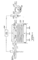
- Adhesive regions 106 are formed at regular intervals along the medium by roller 110 having raised applicator protrusions around its perimeter which pick up adhesive 112 and apply it as a lateral stripe 106 to the medium 27.
- Conventional, pressure-sensitive, gummy adhesives for this application are commonly available, for example, from 3M Company, Minnesota, and can be applied in continuous operation as disclosed. This adhesive adequately holds a unit of currency in gummy fixation upon the medium for easy "peeling" therefrom without damage to the currency.
- a light source and detector 102 at the entrance side of the work station aligns with the apertures 29 and activates the drive means 104 to press the medium 27 with adhesive regions 106 onto the top unit of currency in the supply 100, as illustrated at 113.
- the top unit adheres to the medium 27 in position over the associated aperture 29 and with the leading edge (relative to the illustrated direction of movement of the medium 27) well in advance of the adhesive region 106.
- the units of currency are thus stacked on the medium 27 substantially in parallel-plane relationship 114 to the medium 27.
- the leading edge or forward boundary of each unit of currency is thus free to "peel" away from the medium 27 when the medium 27 is moved over roller 33, as previously described.
- the last unit of "currency" 116 attached to the medium 27 may be dummy currency or a receipt for test operation of the cartridge 13, as previously described.
- Light source and detector 118 may be located on the outlet side of the work station in alignment with the apertures 29 to provide error signal to the drive means 104 for suitably altering its operation in response to detection of an aperture 29 not covered by an adhered unit of currency.
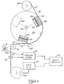
- a section of a currency canister 120 having a plural number of currency bins 122 disposed around the periphery of the canister.
- the currency canister 120 is mounted to rotate about the central axis 124 in response to the transport medium 27 moving along a path that contacts the perimeter of the canister 120.
- the surface velocity of the canister 120 is thus the same as the velocity of the transport medium 27 as the medium 27 is moved incrementally from supply reel 126 to take-up reel 128 under control of the motor drive 43.
- the path taken by the transport medium 27 between supply reel 126 and take-up reel 128 may alternatively pass over the top of the canister 120 (not shown) or pass in a continuous loop between supply and take-up reels 126, 128 (which serve as idler rollers) provided, however, that in each such embodiment the transport medium passes along and in contact with the periphery of the canister 120 with regions of adhesive carried by the transport medium 27, as previously described, disposed on the side thereof facing the periphery of the canister 120.
- One or more currency bins 122 may be disposed about the periphery of the canister 120 to position one unit of currency from each bin 122 in a succession along the transport medium 27 at selected, spaced intervals. Regions of adhesive material 31, as previously described, are positioned along the transport medium to contact the outermost unit of currency in each bin 122 as the transport medium 27 and periphery of the canister 120 move together at the same surface velocity under control of the motor drive 43.
- a pressure roller 133 may be mounted on the opposite side of the transport medium 27 near the location along the path thereof where the periphery of the canister 120 and the transport medium 27 move along divergent.paths.
- This roller 133 is resiliently biased to press the transport medium 27 and the adhesive material 31 carried thereby firmly against the outermost unit of currency in a bin 122 to assure that such outermost unit of currency adheres to the transport medium 27. Then, as the periphery of the canister 120 and the transport medium 27 progress along divergent paths, the adhered unit of currency 131 is extracted from the bin 122 and carried toward the rollers 33, 35 and 37 to be dispensed in the manner previously described.
- FIG. 6 and 7 there are shown plan views of two embodiments of currency-confining apertures associated with the currency bins 122 in the canister 120.
- the bin includes a resiliently-biased platform 135 to urge the units of currency outwardly toward the surface as each outermost unit is extracted from the bin.
- the apertures shown in Figures 6 and 7 each include restrictors that reduce the cross section of the bin at the periphery of the canister 120. These restrictors thus impede the free-flow of currency out of the bin 122 as the canister 120 rotates about its axis 124.
- the restrictors include tabs 137 mounted at the sides of the bin 122 to extend inwardly sufficiently to overlay a portion of the width of a unit of currency.
- the restrictors include a pair of rollers 139 mounted across the ends of the bin transverse to the path of movement of the transport medium 27 also to overlay a portion of the length of a unit of currency.
- the outermost unit of currency in a currency bin 122 contacts the adhesive material 31 carried by the transport medium 27 at the location 141 where the paths of the medium 27 and the periphery of the canister 120 converge.
- the periphery of the canister 120, the transport medium 27 and the adhered unit of currency all travel along substantially the same path at the same surface velocity past the pressure roller 133 which enhances the adhesion of the unit of currency to the medium 27.
- the paths of the periphery of canister 120 and the medium diverge, and the adhered unit of currency 131 is extracted from the bin 122 by "peeling" the unit past the restrictors at the surface of the bin.
- the extracted unit of currency 131 advances toward the dispensing rollers 33, 35 and 37, and the canister 120 rotates to position a successive bin 122 into position for extraction therefrom of the next unit of currency to be dispensed.
- Equal numbers of units of currency may be loaded into the bins 122 in the canister 120, and the total number of such units may be entered into a memory register (not shown) in the machine controller 46'.
- the motor drive 43 may be operated incrementally through a number of currency-dispensing operations, under detection and control of the cartridge control in a manner similar to the operations previously described, until the number of dispensing operations equals the number entered in the memory register of controller 46'.
- any units of currency not properly dispensed and still adhering to the transport medium 27 in take-up reel 128, as detected by cartridge control 44 in the manner previously described can provide indication of the number of units of currency to be retrieved from the take-up reel 128 before it is discarded.
- the present invention includes other embodiments in which the unit of currency to be dispensed travels along a path substantially in contact with, and at the same velocity as, the transport medium.
- a canister having a single currency bin 122 may be used where the canister is mounted only to shuttle angularly or translationally between an initial position and a terminal position with the outermost unit of currency in the bin in contact with, and moving at the same velocity as, the transport medium between such two positions.
- the pressure roller 133 may be an active "pinch" roller that establishes contact between the transport medium and a unit of currency during shuttling of the canister between such two positions to assure adherence of the unit of currency to the transport medium. Thereafter, the transport medium need not be retained in contact with currency in the bin as the canister returns to its initial position for subsequent shuttle movement, as previously described.
- the currency dispenser and method of the present invention provide units of currency to users at remote locations under conditions that insure high degrees of security upon installation and operation.
- currency-dispensing cartridges according to the present invention may directly supply units of currency in different selected denominations for greater versatility compared with conventional prepackaged packets of currency.
- the improved dispensing scheme with internal self-loading permits a stack of currency to be dispensed a unit at a time without the need for preloading at a remote station.
Landscapes
- Physics & Mathematics (AREA)
- General Physics & Mathematics (AREA)
- Business, Economics & Management (AREA)
- Accounting & Taxation (AREA)
- Finance (AREA)
- Engineering & Computer Science (AREA)
- Mechanical Engineering (AREA)
- Sheets, Magazines, And Separation Thereof (AREA)
- Financial Or Insurance-Related Operations Such As Payment And Settlement (AREA)
- Delivering By Means Of Belts And Rollers (AREA)
- Discharge By Other Means (AREA)
Applications Claiming Priority (2)
| Application Number | Priority Date | Filing Date | Title |
|---|---|---|---|
| US06/567,688 US4577779A (en) | 1982-12-01 | 1984-01-03 | Currency-dispensing method and apparatus |
| US567688 | 1984-01-03 |
Publications (3)
| Publication Number | Publication Date |
|---|---|
| EP0151808A2 true EP0151808A2 (fr) | 1985-08-21 |
| EP0151808A3 EP0151808A3 (en) | 1987-09-09 |
| EP0151808B1 EP0151808B1 (fr) | 1990-11-07 |
Family
ID=24268231
Family Applications (1)
| Application Number | Title | Priority Date | Filing Date |
|---|---|---|---|
| EP84116419A Expired - Lifetime EP0151808B1 (fr) | 1984-01-03 | 1984-12-28 | Dispositif et méthode pour la distribution d'argent |
Country Status (4)
| Country | Link |
|---|---|
| US (1) | US4577779A (fr) |
| EP (1) | EP0151808B1 (fr) |
| JP (1) | JPS60159994A (fr) |
| DE (1) | DE3483573D1 (fr) |
Cited By (3)
| Publication number | Priority date | Publication date | Assignee | Title |
|---|---|---|---|---|
| EP1220167A1 (fr) * | 2000-12-28 | 2002-07-03 | Mars Inc. | Entrepôt pour billets de banque |
| WO2004077365A3 (fr) * | 2003-02-28 | 2005-02-10 | Innovative Technology Ltd | Ameliorations apportees a la manipulation et a la distribution de feuilles flexibles |
| US7494122B2 (en) | 2003-01-14 | 2009-02-24 | Alberto Spinetti | Device and method for storing and/or dispensing rigid or flexible substantially planar items |
Families Citing this family (5)
| Publication number | Priority date | Publication date | Assignee | Title |
|---|---|---|---|---|
| JPS6296231A (ja) * | 1985-10-21 | 1987-05-02 | Agency Of Ind Science & Technol | 布状物の把持装置 |
| US6845907B1 (en) * | 1998-11-13 | 2005-01-25 | Diebold, Incorporated | Cash delivery apparatus for motor fuel dispenser or other self service facility |
| US7387236B2 (en) * | 2001-10-09 | 2008-06-17 | Delaware Capital Formation, Inc. | Dispensing of currency |
| US20050098622A1 (en) * | 2001-10-09 | 2005-05-12 | Gregory Jantsch | Dispensing of currency |
| US20070001383A1 (en) * | 2005-06-20 | 2007-01-04 | Gregory Jantsch | Dispensing of currency |
Citations (7)
| Publication number | Priority date | Publication date | Assignee | Title |
|---|---|---|---|---|
| US1779425A (en) | 1927-05-10 | 1930-10-28 | Feybusch Martin | Method and apparatus for handling small articles |
| US3662343A (en) | 1970-07-29 | 1972-05-09 | Docutel Corp | Credit card automatic currency dispenser |
| US3845277A (en) | 1972-09-01 | 1974-10-29 | Mosler Safe Co | Off-line cash dispenser and banking system |
| FR2458492A1 (fr) | 1979-06-11 | 1981-01-02 | Fresnel Jacques | Procede de separation a l'unite et de transfert d'objets plans empiles horizontalement |
| GB2054529A (en) | 1979-06-25 | 1981-02-18 | Hunkeler Ag Jos | Apparatus for applying sheet units to elongate web |
| WO1982000025A1 (fr) | 1980-06-26 | 1982-01-07 | Ncr Co | Distributeur de papiers valeur |
| EP0051076A1 (fr) | 1980-10-30 | 1982-05-12 | Thomas Gläser | Procédé pour munir de feuilles individuelles des bandes de support continues, par exemple des bandes simples continues de documents ainsi que dispositif pour mettre en oeuvre ce procédé |
Family Cites Families (13)
| Publication number | Priority date | Publication date | Assignee | Title |
|---|---|---|---|---|
| GB817154A (en) * | 1955-10-19 | 1959-07-22 | Int Computers & Tabulators Ltd | Improvements in or relating to apparatus for detecting faulty sheet feeding |
| US3436294A (en) * | 1964-05-07 | 1969-04-01 | Flinchbaugh Products Inc | Tape-mounted label dispensing and applying apparatus |
| US3450307A (en) * | 1967-07-26 | 1969-06-17 | American Binder Co The | Envelope separator |
| DE2257293C2 (de) * | 1972-11-22 | 1974-11-14 | Gebr. Mayer, 7750 Konstanz | Vorrichtung zum Ablösen von auf einem Band haftenden Plättchen |
| JPS507892U (fr) * | 1973-05-19 | 1975-01-27 | ||
| US4091987A (en) * | 1976-09-24 | 1978-05-30 | Web Graphics, Inc. | Carrier sheet business form assembly |
| SE413118B (sv) * | 1978-03-21 | 1980-04-14 | Lundblad Leif | For verdehandlingar och/eller verdeforemal avsedd lasbar kassett, box eller dylikt, samt ett kassetten omfattande holje |
| JPS55156148A (en) * | 1979-05-25 | 1980-12-04 | Laurel Bank Mach Co Ltd | Automatic delivery machine |
| SE417023B (sv) * | 1979-11-29 | 1981-02-16 | Leif Lundblad | Anleggning for seker och ekonomiskt optimal hantering av verdedokument inom en penninginrettning |
| US4337864A (en) * | 1980-02-22 | 1982-07-06 | Docutel Corporation | Currency note dispensing system |
| JPS5749902A (en) * | 1980-09-10 | 1982-03-24 | Canon Inc | Pentagonal dach-prism |
| JPS5836899A (ja) * | 1981-08-25 | 1983-03-03 | 日産自動車株式会社 | 産業車両におけるチルトシリンダ |
| US4515288A (en) * | 1982-12-01 | 1985-05-07 | Atalla Corporation | Currency-dispensing method and apparatus |
-
1984
- 1984-01-03 US US06/567,688 patent/US4577779A/en not_active Expired - Fee Related
- 1984-12-28 JP JP59282090A patent/JPS60159994A/ja active Pending
- 1984-12-28 EP EP84116419A patent/EP0151808B1/fr not_active Expired - Lifetime
- 1984-12-28 DE DE8484116419T patent/DE3483573D1/de not_active Expired - Fee Related
Patent Citations (7)
| Publication number | Priority date | Publication date | Assignee | Title |
|---|---|---|---|---|
| US1779425A (en) | 1927-05-10 | 1930-10-28 | Feybusch Martin | Method and apparatus for handling small articles |
| US3662343A (en) | 1970-07-29 | 1972-05-09 | Docutel Corp | Credit card automatic currency dispenser |
| US3845277A (en) | 1972-09-01 | 1974-10-29 | Mosler Safe Co | Off-line cash dispenser and banking system |
| FR2458492A1 (fr) | 1979-06-11 | 1981-01-02 | Fresnel Jacques | Procede de separation a l'unite et de transfert d'objets plans empiles horizontalement |
| GB2054529A (en) | 1979-06-25 | 1981-02-18 | Hunkeler Ag Jos | Apparatus for applying sheet units to elongate web |
| WO1982000025A1 (fr) | 1980-06-26 | 1982-01-07 | Ncr Co | Distributeur de papiers valeur |
| EP0051076A1 (fr) | 1980-10-30 | 1982-05-12 | Thomas Gläser | Procédé pour munir de feuilles individuelles des bandes de support continues, par exemple des bandes simples continues de documents ainsi que dispositif pour mettre en oeuvre ce procédé |
Cited By (4)
| Publication number | Priority date | Publication date | Assignee | Title |
|---|---|---|---|---|
| EP1220167A1 (fr) * | 2000-12-28 | 2002-07-03 | Mars Inc. | Entrepôt pour billets de banque |
| US6786479B2 (en) | 2000-12-28 | 2004-09-07 | Mars Incorporated | Banknote store with a rotatable structure having banknote-storing regions |
| US7494122B2 (en) | 2003-01-14 | 2009-02-24 | Alberto Spinetti | Device and method for storing and/or dispensing rigid or flexible substantially planar items |
| WO2004077365A3 (fr) * | 2003-02-28 | 2005-02-10 | Innovative Technology Ltd | Ameliorations apportees a la manipulation et a la distribution de feuilles flexibles |
Also Published As
| Publication number | Publication date |
|---|---|
| EP0151808A3 (en) | 1987-09-09 |
| US4577779A (en) | 1986-03-25 |
| DE3483573D1 (de) | 1990-12-13 |
| JPS60159994A (ja) | 1985-08-21 |
| EP0151808B1 (fr) | 1990-11-07 |
Similar Documents
| Publication | Publication Date | Title |
|---|---|---|
| US4515288A (en) | Currency-dispensing method and apparatus | |
| US4337864A (en) | Currency note dispensing system | |
| JP4588131B2 (ja) | 自動出納機および自動出納機における紙幣払出方法 | |
| US4844369A (en) | Voucher issuing device and a method of automatically loading continuous voucher forms | |
| EP0056386B1 (fr) | Distributeur de papiers valeur | |
| EP0915436B1 (fr) | Aiguillage pour documents | |
| US4577779A (en) | Currency-dispensing method and apparatus | |
| JP2020194417A (ja) | 媒体処理装置及び媒体取引装置 | |
| CA1234082A (fr) | Methode et appareil de change | |
| GB2134493A (en) | Currency note storing and despensing system | |
| JP2000348235A (ja) | 紙幣収納放出装置およびこれを用いた紙幣入出金機 | |
| KR20010074160A (ko) | 승차권발매기 | |
| JPS58225495A (ja) | 紙幣処理装置 | |
| JP7507546B2 (ja) | 硬貨収納部、硬貨処理装置及び自動取引装置 | |
| JPS6125293A (ja) | 現金自動取引装置 | |
| JPS6073783A (ja) | 自動取引装置 | |
| JPH09180035A (ja) | プリペイドカード管理システム | |
| JPS62135986A (ja) | 紙幣処理方法 | |
| JPH0274277A (ja) | 遊技装置 | |
| JPH0157839B2 (fr) | ||
| JPS60241184A (ja) | 硬貨処理機の取忘れ硬貨回収装置 | |
| JPH0664644B2 (ja) | 自動販売機の紙幣取扱い装置 | |
| JPH01155498A (ja) | 磁気カード自動発売装置 | |
| JPS62264141A (ja) | 紙葉類束放出装置 | |
| JPS61243587A (ja) | 自動取引装置 |
Legal Events
| Date | Code | Title | Description |
|---|---|---|---|
| PUAI | Public reference made under article 153(3) epc to a published international application that has entered the european phase |
Free format text: ORIGINAL CODE: 0009012 |
|
| AK | Designated contracting states |
Designated state(s): CH DE FR GB IT LI SE |
|
| PUAL | Search report despatched |
Free format text: ORIGINAL CODE: 0009013 |
|
| AK | Designated contracting states |
Kind code of ref document: A3 Designated state(s): CH DE FR GB IT LI SE |
|
| 17P | Request for examination filed |
Effective date: 19880309 |
|
| 17Q | First examination report despatched |
Effective date: 19880614 |
|
| GRAA | (expected) grant |
Free format text: ORIGINAL CODE: 0009210 |
|
| AK | Designated contracting states |
Kind code of ref document: B1 Designated state(s): CH DE FR GB IT LI SE |
|
| ITF | It: translation for a ep patent filed | ||
| PGFP | Annual fee paid to national office [announced via postgrant information from national office to epo] |
Ref country code: FR Payment date: 19901127 Year of fee payment: 7 |
|
| PGFP | Annual fee paid to national office [announced via postgrant information from national office to epo] |
Ref country code: SE Payment date: 19901204 Year of fee payment: 7 Ref country code: GB Payment date: 19901204 Year of fee payment: 7 Ref country code: CH Payment date: 19901204 Year of fee payment: 7 |
|
| REF | Corresponds to: |
Ref document number: 3483573 Country of ref document: DE Date of ref document: 19901213 |
|
| PGFP | Annual fee paid to national office [announced via postgrant information from national office to epo] |
Ref country code: DE Payment date: 19901228 Year of fee payment: 7 |
|
| ITTA | It: last paid annual fee | ||
| ET | Fr: translation filed | ||
| PLBE | No opposition filed within time limit |
Free format text: ORIGINAL CODE: 0009261 |
|
| STAA | Information on the status of an ep patent application or granted ep patent |
Free format text: STATUS: NO OPPOSITION FILED WITHIN TIME LIMIT |
|
| 26N | No opposition filed | ||
| PG25 | Lapsed in a contracting state [announced via postgrant information from national office to epo] |
Ref country code: GB Effective date: 19911228 |
|
| PG25 | Lapsed in a contracting state [announced via postgrant information from national office to epo] |
Ref country code: SE Effective date: 19911229 |
|
| PG25 | Lapsed in a contracting state [announced via postgrant information from national office to epo] |
Ref country code: LI Effective date: 19911231 Ref country code: CH Effective date: 19911231 |
|
| GBPC | Gb: european patent ceased through non-payment of renewal fee | ||
| PG25 | Lapsed in a contracting state [announced via postgrant information from national office to epo] |
Ref country code: FR Effective date: 19920831 |
|
| REG | Reference to a national code |
Ref country code: CH Ref legal event code: PL |
|
| PG25 | Lapsed in a contracting state [announced via postgrant information from national office to epo] |
Ref country code: DE Effective date: 19920901 |
|
| REG | Reference to a national code |
Ref country code: FR Ref legal event code: ST |
|
| EUG | Se: european patent has lapsed |
Ref document number: 84116419.7 Effective date: 19920704 |