EP0151854A2 - Optoelektronisches Positionsfühlen - Google Patents
Optoelektronisches Positionsfühlen Download PDFInfo
- Publication number
- EP0151854A2 EP0151854A2 EP19840304900 EP84304900A EP0151854A2 EP 0151854 A2 EP0151854 A2 EP 0151854A2 EP 19840304900 EP19840304900 EP 19840304900 EP 84304900 A EP84304900 A EP 84304900A EP 0151854 A2 EP0151854 A2 EP 0151854A2
- Authority
- EP
- European Patent Office
- Prior art keywords
- detectors
- radiation
- output
- sources
- outputs
- Prior art date
- Legal status (The legal status is an assumption and is not a legal conclusion. Google has not performed a legal analysis and makes no representation as to the accuracy of the status listed.)
- Granted
Links
Images
Classifications
-
- G—PHYSICS
- G01—MEASURING; TESTING
- G01F—MEASURING VOLUME, VOLUME FLOW, MASS FLOW OR LIQUID LEVEL; METERING BY VOLUME
- G01F1/00—Measuring the volume flow or mass flow of fluid or fluent solid material wherein the fluid passes through a meter in a continuous flow
- G01F1/05—Measuring the volume flow or mass flow of fluid or fluent solid material wherein the fluid passes through a meter in a continuous flow by using mechanical effects
- G01F1/20—Measuring the volume flow or mass flow of fluid or fluent solid material wherein the fluid passes through a meter in a continuous flow by using mechanical effects by detection of dynamic effects of the flow
- G01F1/28—Measuring the volume flow or mass flow of fluid or fluent solid material wherein the fluid passes through a meter in a continuous flow by using mechanical effects by detection of dynamic effects of the flow by drag-force, e.g. vane type or impact flowmeter
Definitions
- the present invention relates to a system and method of opto-electronic position sensing.
- Opto-electronic position sensing systems for use with flowmeters are known. These consist of an array of emitters facing an array of detectors, each detector being illuminated by and responsive to a corresponding one only of the emitters. The position of a moveable member is detected by a digital readout from the detectors thereby identifying the position of tne member by its interuption of signals passed from tne emitters to the detectors.
- This known system has several disadvantages. The precision with whicn the position of the member can be determined is dependent upon the pitch of the array of detectors which reaches a limit when the detectors abut each other.
- the known system also has the disadvantage that for accurate determination of the position of the member a relatively large number of detectors and emitters will be required. This results in an expensive system.
- the flow rate sensor comprises a tube 10 and a float 12 within the tube.
- the tube 10 is transparent and is tapered with its largest cross-sectional area being upper most. Fluid flows up the tube 10 and the float 12 is supported at a position determined by the rate of fluid flow. The position of the float 12 also depends upon its own dimensions, the dimensions of the tube and the characteristics of the fluid.
- a scale is associated with the tube 10 and a visual inspection of the position of the float 12 with respect to the scale is used to read off the rate of fluid flow.
- This technique is imprecise and requires a change of scale, or sensor, for use with
- an opto-electronic position sensing system comprising a series of radiation sources, a series of radiation detectors, a movable member having a range of movement over which it controls irradiation of various ones of said detectors by various ones of said sources according to the position of said member, each detector being adapted to produce an analog output signal which varies from a minimum to a maximum with movement of said member over a corresponding part of its range in such manner that the output signal of at least two of said detectors varies with movement of said memDer whatever its position in the said range of movement, and first means which determine the position of the member by digital analysis of outputs from the detectors and second means which subsequently better determine the position of the member by analog analysis of output from those detectors identified by the first means as indicating the position of the member.
- movement of the member is relatively slow and the system comprises means for relatively rapidly energising the sources sequentially and means for relatively rapidly interrogating the detectors sequentially.
- the opto-electronic position sensing system of this invention can accurately determine the position of the float 12 within the tube 10 and this output may then be used for further electronic processing so as to provide a digital readout of the rate of fluid flow.
- the characteristic relating to different fluids may be stored in a look-up table and identification of the fluid flowing within the tube 10 can enable the device to display correctly the flow rate for that fluid.
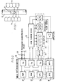
- the opto-electronic system comprises an array of emitters 14 and an array of detectors 16.
- the tube 10 is interposed between the emitters 14 and detectors 16.
- the emitters are off-set from the detectors by half a pitch so that each detector can view two adjacent emitters, as shown by the chain lines.
- the emitters 14 are sequentially energised and the detectors 16 interogated. Therefore sixteen recordings are available from the array of eight detectors.
- the emitters 14 emit infra red radiation and are switched on/off in sequence under micro processor control.
- the pitch of the detectors 16 is 0.2 inches (5.08 mm) for use with a float 12 of at least 5 mm in length.
- the position of the float 12 will be accurately identifiable if the shadow cast by the float 12 on the arry of detectors 16 always overlaps the sensitive area of at least two of the detectors.
- the stagered arrangement of emitters and detectors shown in Figure 1 overcomes problems associated with reduction in sensitivity at the edges of the field of view.
- FIG. 2 is a simplified block diagram of a circuit for activating the emitters 14 and for processing outputs from the detectors 16.
- the circuit comprises a single chip micro processor 18, a number of program select switches 20, a high current driver circuit 22, a light emitting diode display 24, an additional driver 26 for the light emitting diode display 24 and an amplifier 28 which amplifies outputs from the detectors 16.
- the micro processor 18 has input/output ports associated with each of: the switches 20. the high current driver 22 and the additional driver 26.
- the high current driver 22 has outputs for driving the light emitting diode display 24 and for driving the elements 14.
- the micro processor 18 also comprises a ROM 30 which contains programs, a RAM 32 which stores data such as intermediate results and display information, and a CPU 34 which executes the program selected by switches 20.
- the micro processor 18 also includes analog to digital converters 36.
- the micro processor 18 energises the emitters 14 sequentially and relatively rapidly.
- the detectors 16 are interoqated sequentially and relatively rapidly by micro processor 18.
- the speed of movement of float 12 is, by contrast, relatively slow.
- the position of the float 12 is first determined by digital analysis of outputs from the detectors 16 and is susbsequently better determined by analog analysis of output from those detectors 16 which digitally identifiy the position of the float 12.
- the digital analysis merely consists of identifying those detectors 16 whose output is low. Intermediate levels of output are neglected for the digital analysis. It is a practical problem that each of the detectors 16 will have unique charcteristics and similarly each of the emitters 14 can be expected to have unique characteristis.
- a coarse indication of the position of float 12 is given by the digital analysis and the precise algorithm used for the subsequent analog analysis can vary so as to best suit the flow rate sensor and the transducer arrays used with that sensor.
- the above specified dimensions for the arrangement shown in Figure 1 results in the shadow of the float 12 effecting the outputs of at least 2 of the detectors 16.
- the algorithm for analog analysis computes the sum and difference values from the outputs of the two detectors 16 which were identified by the digital analysis as indicating the position of the float 12.
- the ratio of the sum and difference values is considered to indicate the proportional position of the float 12 with respect to the two detectors 16.
- the position of the float 12 is thus accuratly determined by the combined use of digital and analog analysis. It will be appreciated that the precision with which the position of the float 12 can be determined is much enhanced as compared with the prior art purely digital technique, especially when the detectors 16 are located with minimum pitch. Alternately, the number of detectors and emitters required for a specified level of precision can be reduced.
- the above described analog algorithm may be refined in the following manner. Ouput is investigated from that detector 16 subsequent to the two detectors identified by the digital analysis. Three analog signals are thus available for processing and the smallest of the analog signals is subtracted from all three values so as to leave only two non-zero values remaining. The sum and difference of these two values are calculated and their ratio is again considered to indicate the proportional position of the float 12 between the two detectors.
- An alternative analog algorithm is based upon edge detection. If the final output of a detector 16 is a certain percentage of its maximum output then it can be assumed that the float 12 is displaced within the spatial range of that detector with a proportion corresponding to the said percentage. This algorithm can be refined by adding in extra signals from adjacent detectors. This algorithm is considered suitable for flow rate sensors having floats larger than 5 mm in length.
- the described algorithms can be carried out by programs stored in the ROM 30 of the micro processor 18.
- Results of the digital and analog analysis are stored in RAM 32.
- the information can be combined with data relating to the dimensions of tube 10 and float 12 and data relating to characteristics of the fluid flowing in the sensor. This information is processed so as to provide a digital readout on the display 24.
- the system may be further embellished by the provision of features such high and/or low flow rate alarm warnings.
- any range of commercially available microprocessors can be used to implement the described arrangement and each type of microprocessor will provide different capabilities. Therefore it may be necessary to add components, such as RAM, to the standard component.
- Standard programming techniques are employed to implement the described algorithms in a form suitable for processing by the standard microprocessors.
- the staggered array of detectors and emitters can be replaced by aligned arrays in which each emitter illuminates only a respective detector.
- the float 12 can be used to reflect radiation from the emitters onto the detectors. Many variations of the spatial relationship between the emitters and detectors are therefore possible.
- the position sensing system may result from interrogating the detectors sequentially in groups, group-by-group.
- the groups may each include a detector from a preceding group and a detector from a succeeding group.
- Examples of radiation which may be emitted by the emitters 14 are; light, infra red, ultra violet, sonic radiation.
Landscapes
- Fluid Mechanics (AREA)
- General Physics & Mathematics (AREA)
- Physics & Mathematics (AREA)
- Length Measuring Devices By Optical Means (AREA)
- Photo Coupler, Interrupter, Optical-To-Optical Conversion Devices (AREA)
- Moving Of Heads (AREA)
- Vehicle Body Suspensions (AREA)
- Measurement Of Radiation (AREA)
- Geophysics And Detection Of Objects (AREA)
- Polysaccharides And Polysaccharide Derivatives (AREA)
- Non-Silver Salt Photosensitive Materials And Non-Silver Salt Photography (AREA)
- Radiation-Therapy Devices (AREA)
- Length-Measuring Devices Using Wave Or Particle Radiation (AREA)
- Investigating, Analyzing Materials By Fluorescence Or Luminescence (AREA)
Priority Applications (1)
| Application Number | Priority Date | Filing Date | Title |
|---|---|---|---|
| AT84304900T ATE59902T1 (de) | 1983-07-28 | 1984-07-18 | Optoelektronisches positionsfuehlen. |
Applications Claiming Priority (2)
| Application Number | Priority Date | Filing Date | Title |
|---|---|---|---|
| GB8320405 | 1983-07-28 | ||
| GB08320405A GB2144216B (en) | 1983-07-28 | 1983-07-28 | Opto-electronic position sensing |
Publications (3)
| Publication Number | Publication Date |
|---|---|
| EP0151854A2 true EP0151854A2 (de) | 1985-08-21 |
| EP0151854A3 EP0151854A3 (en) | 1988-09-21 |
| EP0151854B1 EP0151854B1 (de) | 1991-01-09 |
Family
ID=10546452
Family Applications (1)
| Application Number | Title | Priority Date | Filing Date |
|---|---|---|---|
| EP19840304900 Expired - Lifetime EP0151854B1 (de) | 1983-07-28 | 1984-07-18 | Optoelektronisches Positionsfühlen |
Country Status (6)
| Country | Link |
|---|---|
| US (1) | US4566337A (de) |
| EP (1) | EP0151854B1 (de) |
| JP (1) | JPS6058576A (de) |
| AT (1) | ATE59902T1 (de) |
| DE (1) | DE3483908D1 (de) |
| GB (1) | GB2144216B (de) |
Families Citing this family (20)
| Publication number | Priority date | Publication date | Assignee | Title |
|---|---|---|---|---|
| US4774676A (en) * | 1984-11-07 | 1988-09-27 | Waukee Engineering Company | Linear digital flowmeter |
| JPS62197787A (ja) * | 1986-02-25 | 1987-09-01 | Minatoerekutoronikusu Kk | 光学式タッチパネルにおける検出回路 |
| US4857050A (en) * | 1987-09-23 | 1989-08-15 | Fisher Scientific Company | Ratiometric air-in-line detector |
| US4864870A (en) * | 1988-07-20 | 1989-09-12 | Waukee Engineering Company | Analog flow meter instrument |
| US4899575A (en) * | 1988-07-29 | 1990-02-13 | Research Foundation Of State University Of New York | Method and apparatus for determining viscosity |
| JP2704946B2 (ja) * | 1988-10-17 | 1998-01-26 | 富士通株式会社 | レチクル及び半導体装置の製造方法 |
| JP2528527B2 (ja) * | 1989-12-27 | 1996-08-28 | 同和鉱業株式会社 | 光学的位置検出装置 |
| US5243183A (en) * | 1992-09-15 | 1993-09-07 | Triad Controls, Inc. | Obstruction position detecting system with comparison and memory means |
| US5379651A (en) * | 1994-02-07 | 1995-01-10 | Semitool, Inc. | Point optical beam electronic rotometer |
| US5824916A (en) * | 1996-12-26 | 1998-10-20 | Posner, Jr.; Paul H. | System for measuring the volume and rate of flow of a media |
| US6901813B2 (en) * | 2003-05-13 | 2005-06-07 | World Wide Plastics, Inc | Flow meter alarm device |
| DE102004011780A1 (de) * | 2004-03-09 | 2005-10-27 | Gerd Reime | Zugangskontrolleinrichtung |
| EP1817541B8 (de) * | 2004-11-09 | 2019-09-18 | PerkinElmer Health Sciences, Inc. | Verfahren und systeme zur bestimmung der position einer sonde |
| US7140262B1 (en) * | 2005-05-05 | 2006-11-28 | Vaughn Neher Technology, Llc | Precision variable area flowmeter apparatus |
| DE102006047537B4 (de) * | 2006-10-07 | 2024-05-16 | Sanofi-Aventis Deutschland Gmbh | Verfahren und Vorrichtung zur Bestimmung der Position eines Stopfens einer Ampulle für ein Arzneimittel in einem medizinischen Gerät sowie deren Verwendung, ein entsprechendes medizinisches Gerät sowie Herstellung eines medizinischen Geräts |
| US7709800B2 (en) * | 2006-12-27 | 2010-05-04 | Nucsafe, Inc. | Method and apparatus for rejecting radioactive interference in a radiation monitoring station |
| US7982201B2 (en) * | 2009-09-08 | 2011-07-19 | Jadak, Llc | System and method for detection of liquid level in a vessel |
| US8695878B2 (en) | 2011-08-31 | 2014-04-15 | Djb Group Llc | Shelf-monitoring system |
| US10955272B2 (en) * | 2017-10-18 | 2021-03-23 | Magnum Venus Products | Catalyst flow sensor |
| US20190041251A1 (en) * | 2018-01-02 | 2019-02-07 | Intel Corporation | Monitor for a flowmeter |
Family Cites Families (14)
| Publication number | Priority date | Publication date | Assignee | Title |
|---|---|---|---|---|
| US2503091A (en) * | 1944-04-26 | 1950-04-04 | Brooke Engineering Company Inc | Electric motor control system |
| US2882520A (en) * | 1953-03-04 | 1959-04-14 | Edward C Hass | Photo-electric sighting device |
| US3582662A (en) * | 1970-04-06 | 1971-06-01 | Abbott Lab | Radiation sensitive electronic flow gauging system |
| US3699560A (en) * | 1970-10-08 | 1972-10-17 | Bendix Corp | Precision position indicator |
| US3845319A (en) * | 1971-10-22 | 1974-10-29 | Sick Erwin | Method and apparatus for the accurate detection of the passage of the edge of a straight contrast jump |
| DE2231776C3 (de) * | 1972-06-29 | 1987-07-30 | Licentia Patent-Verwaltungs-Gmbh, 6000 Frankfurt | Lichtschranke zur Messung der Lage oder Abmessung von Gegenständen |
| DE2544231A1 (de) * | 1975-10-03 | 1977-04-14 | Precitec Gmbh | Lichtschranken-anordnung zur ermittlung flacher, insbesondere bandfoermiger koerper |
| US4084426A (en) * | 1976-08-06 | 1978-04-18 | Jos. Schlitz Brewing Company | Foam monitor and method |
| GB1563570A (en) * | 1976-08-19 | 1980-03-26 | Seiko Instr & Electronics | Hardness tester |
| US4184080A (en) * | 1977-06-30 | 1980-01-15 | Molins Machine Company, Inc. | Ratiometric edge detector system |
| US4200806A (en) * | 1978-04-25 | 1980-04-29 | The United States Of America As Represented By The Department Of Health, Education And Welfare | Scanning flow indicator for rotameters |
| HU183092B (en) * | 1979-03-19 | 1984-04-28 | Mta Mueszaki Kemiai Kutato Int | Apparatus for instrumental measuring and automatic control of streaming fluidal materials |
| DE3103187A1 (de) * | 1981-01-30 | 1982-08-26 | Rota Apparate- Und Maschinenbau Dr. Hennig Gmbh & Co Kg, 7867 Wehr | Schwebekoerper-durchflussmesser |
| GB2111196A (en) * | 1981-09-28 | 1983-06-29 | Platon Limited G A | Indicating or measuring instruments |
-
1983
- 1983-07-28 GB GB08320405A patent/GB2144216B/en not_active Expired
-
1984
- 1984-07-18 AT AT84304900T patent/ATE59902T1/de not_active IP Right Cessation
- 1984-07-18 DE DE8484304900T patent/DE3483908D1/de not_active Expired - Fee Related
- 1984-07-18 EP EP19840304900 patent/EP0151854B1/de not_active Expired - Lifetime
- 1984-07-24 US US06/634,024 patent/US4566337A/en not_active Expired - Fee Related
- 1984-07-27 JP JP59157105A patent/JPS6058576A/ja active Pending
Also Published As
| Publication number | Publication date |
|---|---|
| DE3483908D1 (de) | 1991-02-14 |
| JPS6058576A (ja) | 1985-04-04 |
| GB8320405D0 (en) | 1983-09-01 |
| EP0151854A3 (en) | 1988-09-21 |
| ATE59902T1 (de) | 1991-01-15 |
| GB2144216A (en) | 1985-02-27 |
| EP0151854B1 (de) | 1991-01-09 |
| GB2144216B (en) | 1986-10-22 |
| US4566337A (en) | 1986-01-28 |
Similar Documents
| Publication | Publication Date | Title |
|---|---|---|
| EP0151854B1 (de) | Optoelektronisches Positionsfühlen | |
| US4555633A (en) | Photoelectric dimension measuring system | |
| US5033602A (en) | Device for indentifying coins | |
| US7214954B2 (en) | Method for operating optical sensors | |
| US4962538A (en) | Image analysis counting system | |
| US4739175A (en) | Apparatus for inspecting configuration of terminal legs of an electronic device | |
| US4140395A (en) | Electro-optical method and system for in situ measurements of particle size and distribution | |
| GB2047880A (en) | Determination of characteristics of segmented fluid | |
| US7034937B2 (en) | Flow meter | |
| US4812043A (en) | Method for measuring a physical quantity providing digital data using analog-value measuring devices, and measuring apparatus for applying this method | |
| US20030164944A1 (en) | Apparatus for determining the shape and/or size of little particles | |
| EP0185285A2 (de) | Messapparat für Flüssigkeitspegel | |
| GB2248333A (en) | Arrangement for testing the physical characteristics of coins | |
| WO1987003091A1 (en) | A method and apparatus for detecting the concentration of contaminants in a liquid | |
| EP3550328A1 (de) | Vorrichtung zur detektion und entfernungsmessung mittels gepulstem licht, system und verfahren zur detektion und entfernungsmessung eines objekts in einem system zur detektion und entfernungsmessung mittels gepulstem licht | |
| TW399246B (en) | Method and apparatus for checking shape | |
| US4822170A (en) | Sensor for the contactless linear measurement of the distance of a target by backscattered radiation | |
| KR970704380A (ko) | 생체의 위치결정방법, 생체정보 측정용 위치결정장치 및 생체정보 측정장치(method of positioning living body, positioner for determining biological information, and apparatus for determining biological information) | |
| US4707614A (en) | Self-contained portable photoelectric gas measuring and warning apparatus | |
| US5910663A (en) | Optical system and light emitting diode having a light dividing surface portion | |
| FI70647C (fi) | Apparat foer testning av ett prov av fibrer eller filament | |
| SE8602406D0 (sv) | Sett att bestemma densitet for underliggande lager | |
| EP1258701B1 (de) | Verfahren zur Determinierung von Fraktionen eines Intervals zwischen aufeinander folgenden Photo-elementen in einem linearen optischen Sensor | |
| US20240288464A1 (en) | Optical gate and method for determining a velocity vector of a spherical projectile | |
| RU2289097C1 (ru) | Устройство для рентгеновского контроля толщины слоев биметаллической ленты |
Legal Events
| Date | Code | Title | Description |
|---|---|---|---|
| PUAI | Public reference made under article 153(3) epc to a published international application that has entered the european phase |
Free format text: ORIGINAL CODE: 0009012 |
|
| AK | Designated contracting states |
Kind code of ref document: A2 Designated state(s): AT BE CH DE FR GB IT LI LU NL SE Designated state(s): AT BE CH DE FR GB IT LI LU NL SE |
|
| 17P | Request for examination filed |
Effective date: 19851014 |
|
| PUAL | Search report despatched |
Free format text: ORIGINAL CODE: 0009013 |
|
| AK | Designated contracting states |
Kind code of ref document: A3 Designated state(s): AT BE CH DE FR GB IT LI LU NL SE |
|
| 17Q | First examination report despatched |
Effective date: 19891004 |
|
| RAP3 | Party data changed (applicant data changed or rights of an application transferred) |
Owner name: PLATON FLOW CONTROL LIMITED |
|
| GRAA | (expected) grant |
Free format text: ORIGINAL CODE: 0009210 |
|
| AK | Designated contracting states |
Kind code of ref document: B1 Designated state(s): AT BE CH DE FR GB IT LI LU NL SE |
|
| PG25 | Lapsed in a contracting state [announced via postgrant information from national office to epo] |
Ref country code: SE Effective date: 19910109 Ref country code: NL Effective date: 19910109 Ref country code: IT Free format text: LAPSE BECAUSE OF FAILURE TO SUBMIT A TRANSLATION OF THE DESCRIPTION OR TO PAY THE FEE WITHIN THE PRESCRIBED TIME-LIMIT;WARNING: LAPSES OF ITALIAN PATENTS WITH EFFECTIVE DATE BEFORE 2007 MAY HAVE OCCURRED AT ANY TIME BEFORE 2007. THE CORRECT EFFECTIVE DATE MAY BE DIFFERENT FROM THE ONE RECORDED. Effective date: 19910109 |
|
| REF | Corresponds to: |
Ref document number: 59902 Country of ref document: AT Date of ref document: 19910115 Kind code of ref document: T |
|
| ET | Fr: translation filed | ||
| REF | Corresponds to: |
Ref document number: 3483908 Country of ref document: DE Date of ref document: 19910214 |
|
| RAP4 | Party data changed (patent owner data changed or rights of a patent transferred) |
Owner name: PLATON FLOW CONTROL LIMITED |
|
| NLV1 | Nl: lapsed or annulled due to failure to fulfill the requirements of art. 29p and 29m of the patents act | ||
| PGFP | Annual fee paid to national office [announced via postgrant information from national office to epo] |
Ref country code: GB Payment date: 19910705 Year of fee payment: 8 |
|
| PGFP | Annual fee paid to national office [announced via postgrant information from national office to epo] |
Ref country code: AT Payment date: 19910711 Year of fee payment: 8 |
|
| PGFP | Annual fee paid to national office [announced via postgrant information from national office to epo] |
Ref country code: FR Payment date: 19910721 Year of fee payment: 8 |
|
| PGFP | Annual fee paid to national office [announced via postgrant information from national office to epo] |
Ref country code: CH Payment date: 19910730 Year of fee payment: 8 |
|
| PGFP | Annual fee paid to national office [announced via postgrant information from national office to epo] |
Ref country code: LU Payment date: 19910806 Year of fee payment: 8 |
|
| PGFP | Annual fee paid to national office [announced via postgrant information from national office to epo] |
Ref country code: DE Payment date: 19910830 Year of fee payment: 8 |
|
| PGFP | Annual fee paid to national office [announced via postgrant information from national office to epo] |
Ref country code: BE Payment date: 19910904 Year of fee payment: 8 |
|
| PLBE | No opposition filed within time limit |
Free format text: ORIGINAL CODE: 0009261 |
|
| STAA | Information on the status of an ep patent application or granted ep patent |
Free format text: STATUS: NO OPPOSITION FILED WITHIN TIME LIMIT |
|
| 26N | No opposition filed | ||
| EPTA | Lu: last paid annual fee | ||
| PG25 | Lapsed in a contracting state [announced via postgrant information from national office to epo] |
Ref country code: LU Free format text: LAPSE BECAUSE OF NON-PAYMENT OF DUE FEES Effective date: 19920718 Ref country code: GB Effective date: 19920718 Ref country code: AT Effective date: 19920718 |
|
| PG25 | Lapsed in a contracting state [announced via postgrant information from national office to epo] |
Ref country code: LI Effective date: 19920731 Ref country code: CH Effective date: 19920731 Ref country code: BE Effective date: 19920731 |
|
| BERE | Be: lapsed |
Owner name: PLATON FLOW CONTROL LTD Effective date: 19920731 |
|
| GBPC | Gb: european patent ceased through non-payment of renewal fee |
Effective date: 19920718 |
|
| PG25 | Lapsed in a contracting state [announced via postgrant information from national office to epo] |
Ref country code: FR Effective date: 19930331 |
|
| REG | Reference to a national code |
Ref country code: CH Ref legal event code: PL |
|
| PG25 | Lapsed in a contracting state [announced via postgrant information from national office to epo] |
Ref country code: DE Effective date: 19930401 |
|
| REG | Reference to a national code |
Ref country code: FR Ref legal event code: ST |