EP0151864B1 - Dispositif pour l'examen de pièces de monnaie - Google Patents
Dispositif pour l'examen de pièces de monnaie Download PDFInfo
- Publication number
- EP0151864B1 EP0151864B1 EP84307465A EP84307465A EP0151864B1 EP 0151864 B1 EP0151864 B1 EP 0151864B1 EP 84307465 A EP84307465 A EP 84307465A EP 84307465 A EP84307465 A EP 84307465A EP 0151864 B1 EP0151864 B1 EP 0151864B1
- Authority
- EP
- European Patent Office
- Prior art keywords
- coin
- cross member
- opening
- coil
- plane
- Prior art date
- Legal status (The legal status is an assumption and is not a legal conclusion. Google has not performed a legal analysis and makes no representation as to the accuracy of the status listed.)
- Expired
Links
- 230000007246 mechanism Effects 0.000 claims description 12
- 230000001419 dependent effect Effects 0.000 abstract 1
- 230000000694 effects Effects 0.000 description 3
- 238000013459 approach Methods 0.000 description 2
- 230000002950 deficient Effects 0.000 description 2
- 230000001939 inductive effect Effects 0.000 description 2
- 230000005856 abnormality Effects 0.000 description 1
- 230000007547 defect Effects 0.000 description 1
- 230000008030 elimination Effects 0.000 description 1
- 238000003379 elimination reaction Methods 0.000 description 1
- 230000005484 gravity Effects 0.000 description 1
- 238000004519 manufacturing process Methods 0.000 description 1
- 230000000284 resting effect Effects 0.000 description 1
Images
Classifications
-
- G—PHYSICS
- G07—CHECKING-DEVICES
- G07D—HANDLING OF COINS OR VALUABLE PAPERS, e.g. TESTING, SORTING BY DENOMINATIONS, COUNTING, DISPENSING, CHANGING OR DEPOSITING
- G07D5/00—Testing specially adapted to determine the identity or genuineness of coins, e.g. for segregating coins which are unacceptable or alien to a currency
- G07D5/02—Testing the dimensions, e.g. thickness, diameter; Testing the deformation
Definitions
- This invention relates to the checking of coins and, more generally, to coin accepting mechanisms which operate in accordance with the results of such checking.
- Such mechanisms are used, for example, on vending machines and amusement machines, and operate to accept genuine coins and reject the remainder.
- Rejected coins may be defective in one respect or another, or may be forgeries and it is important to have an accurate system of checking in order to ensure that such forgeries are rejected.
- the great majority of modern coin checking arrangements operate electrically by passing the coin to be checked through an energised test coil and making use of the resultant inductive or eddy current effects or both.
- the resulting of passing a coin through is to obtain some form of output signal indicative of the nature of the coin, and this may either be compared with a reference signal corresponding to the passage of a genuine coin or alternatively it may be fed directly to a micro-processor.
- a micro-processor is capable of discriminating between a number of different denominations of coins, any one of which may be acceptable, but many forms of accepting mechanism are designed for use with only a single denomination of coin and it is primarily with this type of mechanism that the present invention is concerned.
- the signal from the test coil may be compared with a reference signal and this may be derived from a reference coil which has an output effectively identical to that of the test coil, having a core formed either by a genuine coin or its equivalent.
- a reference coil which has an output effectively identical to that of the test coil, having a core formed either by a genuine coin or its equivalent.
- a coin will pass to the acceptence mechanism travelling edge first and the opening through the test coil is in the form of a slot permitting passage of the coin in this attitude. Consequently, when the test signal is generated, i.e. usually when the coin is at the mid-point of its travel through the coil and its diameter lies in the plane of the coil, the portion of the coin which influences the inductive and eddy current effects referred to above is represented by a slice across the diameter of the coin. Any possible defects or abnormalities in the remainder of the coin have little, if any, effect on the signal. This applies particular to non-circular coins such as a fifty pence piece.
- the present invention is based on the principle of passing the coin through the test coil on the flat, that is to say, with the opposite faces of the coin parallel with the plane of the coil, so that virtually the whole volume of the coin affects the output signal.
- the coil is wound on a former having a central opening.of a shape corresponding at least approximately to the outline of a coin to be checked and arranged for mounting with the plane at an angle to the horizontal, the opening in the former having, towards its lower side, a cross member located below the transverse centre line of the coil so that the coin can momentarily rest on the cross member with its plane in the plane of the coil and can then turn above the cross member under its own weight and pass edge-wise through the opening in the former.
- the assembly includes a coin guide for guiding a coin edge-wise in a generally vertical direction towards the lower side of the coil so that a coin emerging edge-wise from the guide enters the part of the opening in the former on the side of the cross member away from the diameter and then turns about the cross member into the plane of the coil.
- the coin approaches the test coil edge-wise in a generally vertical direction, engages the narrower part of the opening through the former, through which it cannot pass, turns about the cross member until it lies in the plane of the coil, at which time the test signal is generated, and then continues its turning movement until it is able to pass edge-wise through the wider part of the opening in the former, after which it continues its travel through the mechanism.
- the test signal thus generated can then be used in any of the different ways referred to previously.
- the arrangement can be used with any type of coin and is found to provide a considerably more accurate indication of the properties of many coins than with previous types of test coil.
- this part of the opening i.e. that on the side of the cross member away from the diameter, preferably has radiused corners where the cross member meets the circumference of the opening.
- the cross member may be made movable so that if a jam occurs, it may be released by movement of the cross member.
- any jam may be made more effective by mounting the cross member on a pivoted lever which is so shaped that when it is turned about its pivot to move the cross member downwardly out of the opening a nose portion enters the opening at the top to clear any obstruction. Not only is the cross member moved out of the way, but any jammed coin or other form of obstruction is forced downwardly to clear the opening.
- An assembly of test coil and coin guide in accordance with the invention forms one component of a complete acceptor mechanism, of which the other essential components are a power source for energising the coil, a circuit for detecting the response to the presence of a coin with its plane in the plane of the coil and for producing a corresponding output signal and means responsive to the output signal for accepting or rejecting the coin as it falls from the coil.
- the assembly must, of course, be so designed as to be capable of being installed in the correct attitude, that is to say with the plane of the opening in the former at an angle to the horizontal and the coin guide substantially vertical. It is found in practice that best results are obtained when the plane of the opening is at an angle of approximately 30° to the horizontal, and the assembly needs to be designed to make this possible.
- the coin guide need not be strictly vertical, and provided it does not depart from the vertical by more than a few degrees, consistent results are obtainable.
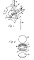
- a test coil 1 is wound on a former 2 which has a central opening (seen in Figure 2) of a shape corresponding to the outline of the particular denomination of coin to be checked, in the example a fifty pence piece,
- the coin is seven-sided, each side having a slight curvature as seen at 3 in Figure 2.
- the central opening 4 in the former 2 differs slightly from this in that it is circular and is slightly larger than the coin itself, so that the latter may pass freely through the opening.
- a cross member 6 having its lower surface level with that of the former 2 extends across the opening 4 so as to divide it into two unequal portions 7 and 8.
- the former 2 is mounted for operation at an angle to the horizontal with the cross member 6 towards its lower side. The precise angle of inclination to the horizontal depends on the coin being checked and the dimension of the former 2, but an angle in the region of 30° is found to be appropriate for most circumstances. In the example illustrated, the angle is 32°.
- the lower side of the cross member 6 is level with the lower side of the former 2 and the upper side of the member is just below the transverse centre line of the coil so that a coin resting momentarily on the cross member in the position indicated as 3b lies in the plane of the coil 1.
- This position is only momentary because the centre of gravity of the coin lies to the right of the cross member 6 as seen in Figure 1, and this causes the coin to turn in a clock-wise direction until it is substantially vertical, when it falls through the larger portion 8 of the opening 4 into the position shown as 3c.
- the right hand side of the cross member 6 as seen in Figure 1 is to the left of the corresponding diameter of the opening 4, so that there is a clear passage for the coin along the diameter of the opening.
- a coin is guided to the former 2 by a guide 10 which is illustrated in Figure 1 as vertical. Strict verticality is not essential, however, and the guide may depart from the vertical by a few degrees, particularly in a clockwise direction where the departure may be up to about 15°.
- a coin just leaving the guide 10 in a vertical attitude is shown as 3a and the corresponding position for a coin leaving a guide inclined to the vertical is shown in dotted lines as 3a'.
- the guide 10 is so located in relation to the former 2 that the coin enters the narrower portion 7 of the opening 4 as seen in Figure 1.
- the coin cannot pass through this relatively narrow space and instead pivots about the cross member 6 until it reaches the position 3b in the plane of the coil 1 as previously described.
- this space has radiused corners 11 where the cross member 6 meets the circumference of the opening. If, despite the presence of these radiuses, a jam occurs, this can be freed by means of a reject lever 12 which is pivoted at 13.
- the lever has one arm 14 which supports the cross member 6 and a second arm 15 shaped to define a nose portion 16.
- a coin to be checked approaches the coil 2 in the position 3a and then turns through slightly less than a right angle to the position 3b where the checking action occurs as the result of energisation of the coil 1 and production of an output signal indicative of the nature of coin.
- the position 3b is only momentary and the coin continues its turning movement until it reaches a generally vertical position when it falls through the larger space 8 in a generally vertical attitude, as shown at 3c.
Landscapes
- Physics & Mathematics (AREA)
- General Physics & Mathematics (AREA)
- Testing Of Coins (AREA)
- Control Of Vending Devices And Auxiliary Devices For Vending Devices (AREA)
- Noodles (AREA)
- Pinball Game Machines (AREA)
- Chair Legs, Seat Parts, And Backrests (AREA)
- Investigating Materials By The Use Of Optical Means Adapted For Particular Applications (AREA)
- Inspection Of Paper Currency And Valuable Securities (AREA)
Claims (6)
Priority Applications (1)
| Application Number | Priority Date | Filing Date | Title |
|---|---|---|---|
| AT84307465T ATE45052T1 (de) | 1984-01-03 | 1984-10-30 | Muenzpruefeinrichtung. |
Applications Claiming Priority (2)
| Application Number | Priority Date | Filing Date | Title |
|---|---|---|---|
| GB8400046 | 1984-01-03 | ||
| GB848400046A GB8400046D0 (en) | 1984-01-03 | 1984-01-03 | Coin checking |
Publications (3)
| Publication Number | Publication Date |
|---|---|
| EP0151864A2 EP0151864A2 (fr) | 1985-08-21 |
| EP0151864A3 EP0151864A3 (en) | 1986-09-10 |
| EP0151864B1 true EP0151864B1 (fr) | 1989-07-26 |
Family
ID=10554503
Family Applications (1)
| Application Number | Title | Priority Date | Filing Date |
|---|---|---|---|
| EP84307465A Expired EP0151864B1 (fr) | 1984-01-03 | 1984-10-30 | Dispositif pour l'examen de pièces de monnaie |
Country Status (7)
| Country | Link |
|---|---|
| US (1) | US4662501A (fr) |
| EP (1) | EP0151864B1 (fr) |
| JP (1) | JPS60147897A (fr) |
| AT (1) | ATE45052T1 (fr) |
| DE (1) | DE3479170D1 (fr) |
| ES (1) | ES538435A0 (fr) |
| GB (1) | GB8400046D0 (fr) |
Families Citing this family (6)
| Publication number | Priority date | Publication date | Assignee | Title |
|---|---|---|---|---|
| US5067604A (en) * | 1988-11-14 | 1991-11-26 | Bally Manufacturing Corporation | Self teaching coin discriminator |
| DE4233194C2 (de) * | 1992-10-02 | 1995-09-21 | Nat Rejectors Gmbh | Verfahren zum Eichen eines mindestens eine Münze akzeptierenden Münzprüfers und Eichmodul |
| US5524143A (en) * | 1993-01-12 | 1996-06-04 | Turk; Nathan N. | Anti-stuffing coin realigner |
| JP4446053B2 (ja) * | 2004-11-17 | 2010-04-07 | 旭精工株式会社 | コインセレクター |
| JP6425878B2 (ja) * | 2013-10-18 | 2018-11-21 | 株式会社日本コンラックス | 硬貨処理装置 |
| JP7369404B2 (ja) * | 2021-03-08 | 2023-10-26 | 旭精工株式会社 | コインセレクターおよび自動サービス機 |
Family Cites Families (8)
| Publication number | Priority date | Publication date | Assignee | Title |
|---|---|---|---|---|
| US2129512A (en) * | 1936-08-17 | 1938-09-06 | Marshall Seeburg N | Apparatus for separating genuine and spurious coins |
| US3241751A (en) * | 1964-02-12 | 1966-03-22 | Burgess Day Inc | Coin turning chute |
| US3317016A (en) * | 1965-05-21 | 1967-05-02 | Int Nickel Co | Coin selecting device |
| GB1483192A (en) * | 1973-11-22 | 1977-08-17 | Mars Inc | Arrival sensor |
| JPS639019Y2 (fr) * | 1979-11-22 | 1988-03-17 | ||
| DE3014792A1 (de) * | 1980-04-17 | 1981-10-22 | Nsm-Apparatebau Gmbh & Co Kg, 6530 Bingen | Anordnung zum identifizieren von opjekten |
| GB2092798B (en) * | 1981-01-22 | 1984-06-06 | Coin Control Ltd | Coin discriminator |
| GB2096812B (en) * | 1981-02-18 | 1985-06-05 | Appliance Components Ltd | Validation of coins and tokens |
-
1984
- 1984-01-03 GB GB848400046A patent/GB8400046D0/en active Pending
- 1984-10-30 EP EP84307465A patent/EP0151864B1/fr not_active Expired
- 1984-10-30 DE DE8484307465T patent/DE3479170D1/de not_active Expired
- 1984-10-30 AT AT84307465T patent/ATE45052T1/de not_active IP Right Cessation
- 1984-11-06 US US06/668,851 patent/US4662501A/en not_active Expired - Fee Related
- 1984-11-28 JP JP59249830A patent/JPS60147897A/ja active Pending
- 1984-12-10 ES ES538435A patent/ES538435A0/es active Granted
Also Published As
| Publication number | Publication date |
|---|---|
| ATE45052T1 (de) | 1989-08-15 |
| EP0151864A2 (fr) | 1985-08-21 |
| ES8600823A1 (es) | 1985-11-01 |
| ES538435A0 (es) | 1985-11-01 |
| US4662501A (en) | 1987-05-05 |
| DE3479170D1 (en) | 1989-08-31 |
| JPS60147897A (ja) | 1985-08-03 |
| EP0151864A3 (en) | 1986-09-10 |
| GB8400046D0 (en) | 1984-02-08 |
Similar Documents
| Publication | Publication Date | Title |
|---|---|---|
| US3782543A (en) | Document recognition systems | |
| EP0134686B1 (fr) | Dispositif pour l'examen de pièces de monnaie | |
| US4681204A (en) | Device for counting and sorting coins belonging to a set of coins | |
| US3373856A (en) | Method and apparatus for coin selection | |
| JP2599347B2 (ja) | コイル測寸方法 | |
| US5042635A (en) | Rapid coin acceptor | |
| US5433310A (en) | Coin discriminator with offset null coils | |
| JPH04357575A (ja) | 通貨認識のための方法 | |
| JPS6051159B2 (ja) | 複数の額面のコインの真贋性と額面を決定する装置 | |
| EP0151864B1 (fr) | Dispositif pour l'examen de pièces de monnaie | |
| US5496212A (en) | Coin sorting device | |
| US4582189A (en) | Coin validation apparatus | |
| US3980168A (en) | Method and apparatus for authenticating and identifying coins | |
| US5460256A (en) | Coin sensor device | |
| US3672481A (en) | Variable magnetic flux coin-sensing devices | |
| GB2105893A (en) | A coin segregator | |
| US4546868A (en) | Coin testing apparatus | |
| GB2096812A (en) | Validation of coins and tokens | |
| US4574935A (en) | Coin checking method and apparatus employing wave train comparison | |
| US3145821A (en) | Coin testing device | |
| EP0500366B1 (fr) | Méchanisme de validation d'un jeton | |
| EP0047172B1 (fr) | Dispositif de déblocage et leur distribution automatique de denrées actionné par pièces de monnaie | |
| US7617922B2 (en) | Coin acceptor | |
| US3323627A (en) | Apparatus for sorting coins | |
| GB2071382A (en) | Coin Testing Device |
Legal Events
| Date | Code | Title | Description |
|---|---|---|---|
| PUAI | Public reference made under article 153(3) epc to a published international application that has entered the european phase |
Free format text: ORIGINAL CODE: 0009012 |
|
| AK | Designated contracting states |
Designated state(s): AT DE FR GB IT NL |
|
| PUAL | Search report despatched |
Free format text: ORIGINAL CODE: 0009013 |
|
| AK | Designated contracting states |
Kind code of ref document: A3 Designated state(s): AT DE FR GB IT NL |
|
| 17P | Request for examination filed |
Effective date: 19870305 |
|
| 17Q | First examination report despatched |
Effective date: 19881019 |
|
| GRAA | (expected) grant |
Free format text: ORIGINAL CODE: 0009210 |
|
| AK | Designated contracting states |
Kind code of ref document: B1 Designated state(s): AT DE FR GB IT NL |
|
| PG25 | Lapsed in a contracting state [announced via postgrant information from national office to epo] |
Ref country code: NL Effective date: 19890726 Ref country code: IT Free format text: LAPSE BECAUSE OF FAILURE TO SUBMIT A TRANSLATION OF THE DESCRIPTION OR TO PAY THE FEE WITHIN THE PRESCRIBED TIME-LIMIT;WARNING: LAPSES OF ITALIAN PATENTS WITH EFFECTIVE DATE BEFORE 2007 MAY HAVE OCCURRED AT ANY TIME BEFORE 2007. THE CORRECT EFFECTIVE DATE MAY BE DIFFERENT FROM THE ONE RECORDED. Effective date: 19890726 Ref country code: FR Free format text: THE PATENT HAS BEEN ANNULLED BY A DECISION OF A NATIONAL AUTHORITY Effective date: 19890726 Ref country code: AT Effective date: 19890726 |
|
| REF | Corresponds to: |
Ref document number: 45052 Country of ref document: AT Date of ref document: 19890815 Kind code of ref document: T |
|
| REF | Corresponds to: |
Ref document number: 3479170 Country of ref document: DE Date of ref document: 19890831 |
|
| PG25 | Lapsed in a contracting state [announced via postgrant information from national office to epo] |
Ref country code: GB Effective date: 19891030 |
|
| EN | Fr: translation not filed | ||
| NLV1 | Nl: lapsed or annulled due to failure to fulfill the requirements of art. 29p and 29m of the patents act | ||
| PLBE | No opposition filed within time limit |
Free format text: ORIGINAL CODE: 0009261 |
|
| STAA | Information on the status of an ep patent application or granted ep patent |
Free format text: STATUS: NO OPPOSITION FILED WITHIN TIME LIMIT |
|
| GBPC | Gb: european patent ceased through non-payment of renewal fee | ||
| PG25 | Lapsed in a contracting state [announced via postgrant information from national office to epo] |
Ref country code: DE Effective date: 19900703 |
|
| 26N | No opposition filed |