EP0151968A2 - Système d'alimentation de matière lubrifiante - Google Patents
Système d'alimentation de matière lubrifiante Download PDFInfo
- Publication number
- EP0151968A2 EP0151968A2 EP85100606A EP85100606A EP0151968A2 EP 0151968 A2 EP0151968 A2 EP 0151968A2 EP 85100606 A EP85100606 A EP 85100606A EP 85100606 A EP85100606 A EP 85100606A EP 0151968 A2 EP0151968 A2 EP 0151968A2
- Authority
- EP
- European Patent Office
- Prior art keywords
- tank
- lubricant
- supply system
- lubricant supply
- consumer
- Prior art date
- Legal status (The legal status is an assumption and is not a legal conclusion. Google has not performed a legal analysis and makes no representation as to the accuracy of the status listed.)
- Granted
Links
- 239000000314 lubricant Substances 0.000 title claims abstract description 29
- 239000012530 fluid Substances 0.000 claims abstract 2
- 230000005540 biological transmission Effects 0.000 claims 1
- 238000001816 cooling Methods 0.000 claims 1
- 239000003921 oil Substances 0.000 description 5
- 230000004048 modification Effects 0.000 description 2
- 238000012986 modification Methods 0.000 description 2
- 239000010687 lubricating oil Substances 0.000 description 1
- 238000011084 recovery Methods 0.000 description 1
- 238000009987 spinning Methods 0.000 description 1
- 230000003068 static effect Effects 0.000 description 1
- 238000003756 stirring Methods 0.000 description 1
Images
Classifications
-
- F—MECHANICAL ENGINEERING; LIGHTING; HEATING; WEAPONS; BLASTING
- F02—COMBUSTION ENGINES; HOT-GAS OR COMBUSTION-PRODUCT ENGINE PLANTS
- F02C—GAS-TURBINE PLANTS; AIR INTAKES FOR JET-PROPULSION PLANTS; CONTROLLING FUEL SUPPLY IN AIR-BREATHING JET-PROPULSION PLANTS
- F02C7/00—Features, components parts, details or accessories, not provided for in, or of interest apart form groups F02C1/00 - F02C6/00; Air intakes for jet-propulsion plants
- F02C7/06—Arrangements of bearings; Lubricating
-
- F—MECHANICAL ENGINEERING; LIGHTING; HEATING; WEAPONS; BLASTING
- F01—MACHINES OR ENGINES IN GENERAL; ENGINE PLANTS IN GENERAL; STEAM ENGINES
- F01D—NON-POSITIVE DISPLACEMENT MACHINES OR ENGINES, e.g. STEAM TURBINES
- F01D25/00—Component parts, details, or accessories, not provided for in, or of interest apart from, other groups
- F01D25/18—Lubricating arrangements
- F01D25/20—Lubricating arrangements using lubrication pumps
-
- F—MECHANICAL ENGINEERING; LIGHTING; HEATING; WEAPONS; BLASTING
- F16—ENGINEERING ELEMENTS AND UNITS; GENERAL MEASURES FOR PRODUCING AND MAINTAINING EFFECTIVE FUNCTIONING OF MACHINES OR INSTALLATIONS; THERMAL INSULATION IN GENERAL
- F16N—LUBRICATING
- F16N19/00—Lubricant containers for use in lubricators or lubrication systems
-
- F—MECHANICAL ENGINEERING; LIGHTING; HEATING; WEAPONS; BLASTING
- F16—ENGINEERING ELEMENTS AND UNITS; GENERAL MEASURES FOR PRODUCING AND MAINTAINING EFFECTIVE FUNCTIONING OF MACHINES OR INSTALLATIONS; THERMAL INSULATION IN GENERAL
- F16N—LUBRICATING
- F16N39/00—Arrangements for conditioning of lubricants in the lubricating system
- F16N39/06—Arrangements for conditioning of lubricants in the lubricating system by filtration
Definitions
- the invention relates to a lubricant supply system for an engine with a gas turbine. It is based on a state of the art such as is contained in DE-OS 30 47 719.
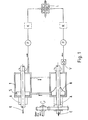
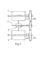
- the object of the present invention is a further improvement of the known lubricant supply system in that the energy still inherent in the return oil (static and kinetic energy) can be used to drive a rotating tank.
- This task is solved by connecting the lubricant tank in series, a centrifugal pump supplying it with lubricant and an air separator. These parts are advantageously spatially separated in the system. Your assignment may vary. The supply or discharge of the lubricant is advantageously controllable.
- the invention also includes all combinations and sub-combinations of the claimed described and illustrated features, both with one another and with features from the prior art.
- FIG. 1 the separator for air can be assigned either to the centrifugal pump R or to the tank T, while in the embodiment of the invention according to FIG. 2 the separator is arranged between the centrifugal pump R and the tank T.
- a modification of the versions shown is to only rotate the tank contents instead of the tank, either directly (e.g. from the inside by stirring) or indirectly (e.g. from the outside by spinning or magnetically).
Landscapes
- Engineering & Computer Science (AREA)
- General Engineering & Computer Science (AREA)
- Mechanical Engineering (AREA)
- Chemical & Material Sciences (AREA)
- Combustion & Propulsion (AREA)
- Lubrication Details And Ventilation Of Internal Combustion Engines (AREA)
- Lubricants (AREA)
- Processes Of Treating Macromolecular Substances (AREA)
Applications Claiming Priority (2)
| Application Number | Priority Date | Filing Date | Title |
|---|---|---|---|
| DE19843405366 DE3405366A1 (de) | 1984-02-15 | 1984-02-15 | Schmiermittelversorgungssystem |
| DE3405366 | 1984-02-15 |
Publications (3)
| Publication Number | Publication Date |
|---|---|
| EP0151968A2 true EP0151968A2 (fr) | 1985-08-21 |
| EP0151968A3 EP0151968A3 (en) | 1988-01-27 |
| EP0151968B1 EP0151968B1 (fr) | 1990-01-03 |
Family
ID=6227787
Family Applications (1)
| Application Number | Title | Priority Date | Filing Date |
|---|---|---|---|
| EP19850100606 Expired - Lifetime EP0151968B1 (fr) | 1984-02-15 | 1985-01-22 | Système d'alimentation de matière lubrifiante |
Country Status (3)
| Country | Link |
|---|---|
| EP (1) | EP0151968B1 (fr) |
| JP (1) | JPS60192166A (fr) |
| DE (1) | DE3405366A1 (fr) |
Cited By (3)
| Publication number | Priority date | Publication date | Assignee | Title |
|---|---|---|---|---|
| WO2007006253A1 (fr) * | 2005-07-07 | 2007-01-18 | Mtu Aero Engines Gmbh | Systeme de lubrification |
| FR3002980A1 (fr) * | 2013-03-07 | 2014-09-12 | Snecma | Groupe de lubrification pour une turbomachine |
| WO2017085430A1 (fr) * | 2015-11-19 | 2017-05-26 | Safran Aircraft Engines | Systeme d'alimentation en fluide de lubrification d'au moins un organe d'un ensemble propulsif d'aeronef et un tel procédé |
Families Citing this family (1)
| Publication number | Priority date | Publication date | Assignee | Title |
|---|---|---|---|---|
| DE3432198C2 (de) * | 1984-09-01 | 1986-08-21 | Heidelberger Druckmaschinen Ag, 6900 Heidelberg | Verfahren zum Steuern des Hubantriebs am Bogenanleger von Druckmaschinen und Bogenanleger zur Durchführung des Verfahrens |
Family Cites Families (9)
| Publication number | Priority date | Publication date | Assignee | Title |
|---|---|---|---|---|
| US2268653A (en) * | 1940-09-18 | 1942-01-06 | Laval Separator Co De | Apparatus and process for purifying airplane engine oil |
| US2888097A (en) * | 1957-07-12 | 1959-05-26 | Westinghouse Electric Corp | Lubrication system |
| US2952329A (en) * | 1957-10-25 | 1960-09-13 | Richard G Cunningham | Device for de-aerating liquids |
| US3722212A (en) * | 1971-03-04 | 1973-03-27 | Avco Corp | Gas turbine engine lubrication system |
| JPS484446U (fr) * | 1971-06-14 | 1973-01-19 | ||
| US4153141A (en) * | 1977-06-20 | 1979-05-08 | General Electric Company | Auxiliary oil supply system |
| DE3137947C2 (de) * | 1980-09-26 | 1983-10-27 | Rolls-Royce Ltd., London | Für beliebige Flugmanöver taugliches Schmierölsystem für Gasturbinentriebwerke |
| DE3047719C2 (de) * | 1980-12-18 | 1983-10-27 | MTU Motoren- und Turbinen-Union München GmbH, 8000 München | Einrichtung zur Entlüftung eines Flüssigkeitsbehälters, insbesondere eines Schmiermittelbehälters für Flugzeuge bei extremen Fluglagen und -bedingungen |
| DE3242366C2 (de) * | 1982-11-16 | 1985-02-07 | MTU Motoren- und Turbinen-Union München GmbH, 8000 München | Ölversorgungseinrichtung für beliebigen Flugsituationen aussetzbare Gasturbinentriebwerke |
-
1984
- 1984-02-15 DE DE19843405366 patent/DE3405366A1/de active Granted
-
1985
- 1985-01-22 EP EP19850100606 patent/EP0151968B1/fr not_active Expired - Lifetime
- 1985-02-13 JP JP2750985A patent/JPS60192166A/ja active Granted
Cited By (6)
| Publication number | Priority date | Publication date | Assignee | Title |
|---|---|---|---|---|
| WO2007006253A1 (fr) * | 2005-07-07 | 2007-01-18 | Mtu Aero Engines Gmbh | Systeme de lubrification |
| US8807282B2 (en) | 2005-07-07 | 2014-08-19 | Mtu Aero Engines Gmbh | Lubricant system |
| FR3002980A1 (fr) * | 2013-03-07 | 2014-09-12 | Snecma | Groupe de lubrification pour une turbomachine |
| WO2017085430A1 (fr) * | 2015-11-19 | 2017-05-26 | Safran Aircraft Engines | Systeme d'alimentation en fluide de lubrification d'au moins un organe d'un ensemble propulsif d'aeronef et un tel procédé |
| FR3044044A1 (fr) * | 2015-11-19 | 2017-05-26 | Snecma | Systeme d'alimentation en fluide d'au moins un organe d'un ensemble propulsif d'aeronef |
| US10934889B2 (en) | 2015-11-19 | 2021-03-02 | Safran Aircraft Engines | System and method for supplying lubrication fluid to at least one member of an aircraft propulsion assembly |
Also Published As
| Publication number | Publication date |
|---|---|
| JPS60192166A (ja) | 1985-09-30 |
| EP0151968A3 (en) | 1988-01-27 |
| DE3405366C2 (fr) | 1989-01-05 |
| JPS6330551B2 (fr) | 1988-06-20 |
| EP0151968B1 (fr) | 1990-01-03 |
| DE3405366A1 (de) | 1985-08-22 |
Similar Documents
| Publication | Publication Date | Title |
|---|---|---|
| DE3137947C2 (de) | Für beliebige Flugmanöver taugliches Schmierölsystem für Gasturbinentriebwerke | |
| DE3522595C2 (fr) | ||
| DE2909878C2 (de) | Vorrichtung zur Abführung des Leckflusses eines hydraulischen Lagermediums | |
| DE69006453T2 (de) | Schmierölrückgewinnungssystem. | |
| DE3242366A1 (de) | Fluessigkeitsversorgungsystem fuer gasturbinentriebwerke, insbesondere oelversorgungssystem fuer gasturbinenstrahltriebwerke von flugzeugen | |
| DE2213731A1 (de) | Zentrifugalpumpe | |
| DE2606978A1 (de) | Schmiersystem zum schmieren der lager, vorzugsweise einer turbine | |
| DE2403159C3 (de) | Anlage zum Kühlen von an Bord eines Flugzeugs befindlichem Brennstoff | |
| DE3034941A1 (de) | Mit aerosol arbeitende hilfs-schmiervorrichtung, insbesondere fuer fluggeraete | |
| DE102013214758A1 (de) | Anordnung zur Ölversorgung eines Automatgetriebes | |
| EP0151968A2 (fr) | Système d'alimentation de matière lubrifiante | |
| DE2034188C3 (de) | Schmiervorrichtung fur Gastur binentriebwerke | |
| DE1288446B (de) | Startbeschleunigungsanlage fuer Luftfahrzeuge | |
| DE2255769A1 (de) | Verfahren zum anfahren eines mit einem arbeitsmedium im geschlossenen kreislauf arbeitenden systems und vorrichtung zur durchfuehrung des verfahrens | |
| DE836131C (de) | Schmiervorrichtung fuer die Wellenlager von mit hoher Drehzahl umlaufenden, mit einem Verdichter ausgeruesteten Triebwerken | |
| EP0188713B1 (fr) | Dispositif de refoulement d'huile pour pompes à vide | |
| DE4034012A1 (de) | Schmiersystem für Flugzeugtriebwerke | |
| DE2527238A1 (de) | Verfahren und vorrichtung zum ableiten des oelueberschusses aus dem getriebegehaeuse eines rotationskompressors mit oeleinspritzung | |
| EP1899583A1 (fr) | Systeme de lubrification | |
| DE746114C (de) | Einrichtung zum Abdichten der Wellen von Turbomaschinen von Waermekraftanlagen, in welchen ein gasfoermiges Arbeitsmittel im wesentlichen einen geschlossenen Kreislauf unter UEberdruck beschreibt | |
| DE3209251C2 (de) | Verfahren zum Hindrängen von in einem Behälter im schwerelosen Zustand befindlicher Flüssigkeit zu Ausflußöffnungen hin sowie Vorrichtung zur Durchführung des Verfahrens | |
| DE1167966C2 (de) | Abdichtungsvorrichtung zwischen einer Gasumwaelzpumpe und dem fluessigkeitsgefuellten elektrischen Antriebsmotor | |
| DE131155C (fr) | ||
| DE1097224B (de) | Wellendichtung | |
| DE519635C (de) | Kuehlfluessigkeitsfoerderanlage fuer Oberflaechenkondensation des Abdampfes von Dampfmaschinen |
Legal Events
| Date | Code | Title | Description |
|---|---|---|---|
| PUAI | Public reference made under article 153(3) epc to a published international application that has entered the european phase |
Free format text: ORIGINAL CODE: 0009012 |
|
| AK | Designated contracting states |
Designated state(s): DE FR GB IT |
|
| PUAL | Search report despatched |
Free format text: ORIGINAL CODE: 0009013 |
|
| AK | Designated contracting states |
Kind code of ref document: A3 Designated state(s): DE FR GB IT |
|
| 17P | Request for examination filed |
Effective date: 19880310 |
|
| 17Q | First examination report despatched |
Effective date: 19890118 |
|
| ITF | It: translation for a ep patent filed | ||
| GRAA | (expected) grant |
Free format text: ORIGINAL CODE: 0009210 |
|
| AK | Designated contracting states |
Kind code of ref document: B1 Designated state(s): FR GB IT |
|
| ET | Fr: translation filed | ||
| GBT | Gb: translation of ep patent filed (gb section 77(6)(a)/1977) | ||
| PLBE | No opposition filed within time limit |
Free format text: ORIGINAL CODE: 0009261 |
|
| STAA | Information on the status of an ep patent application or granted ep patent |
Free format text: STATUS: NO OPPOSITION FILED WITHIN TIME LIMIT |
|
| 26N | No opposition filed | ||
| ITTA | It: last paid annual fee | ||
| REG | Reference to a national code |
Ref country code: GB Ref legal event code: 746 Effective date: 19960215 |
|
| REG | Reference to a national code |
Ref country code: FR Ref legal event code: D6 |
|
| PGFP | Annual fee paid to national office [announced via postgrant information from national office to epo] |
Ref country code: GB Payment date: 19980112 Year of fee payment: 14 |
|
| PGFP | Annual fee paid to national office [announced via postgrant information from national office to epo] |
Ref country code: FR Payment date: 19980116 Year of fee payment: 14 |
|
| PG25 | Lapsed in a contracting state [announced via postgrant information from national office to epo] |
Ref country code: GB Free format text: LAPSE BECAUSE OF NON-PAYMENT OF DUE FEES Effective date: 19990122 |
|
| GBPC | Gb: european patent ceased through non-payment of renewal fee |
Effective date: 19990122 |
|
| PG25 | Lapsed in a contracting state [announced via postgrant information from national office to epo] |
Ref country code: FR Free format text: LAPSE BECAUSE OF NON-PAYMENT OF DUE FEES Effective date: 19990930 |
|
| REG | Reference to a national code |
Ref country code: FR Ref legal event code: ST |