EP0152015B1 - Dispositif pour loger des barres d'armatures - Google Patents
Dispositif pour loger des barres d'armatures Download PDFInfo
- Publication number
- EP0152015B1 EP0152015B1 EP85100954A EP85100954A EP0152015B1 EP 0152015 B1 EP0152015 B1 EP 0152015B1 EP 85100954 A EP85100954 A EP 85100954A EP 85100954 A EP85100954 A EP 85100954A EP 0152015 B1 EP0152015 B1 EP 0152015B1
- Authority
- EP
- European Patent Office
- Prior art keywords
- reinforcing steel
- steel bars
- openings
- cardboard
- areas
- Prior art date
- Legal status (The legal status is an assumption and is not a legal conclusion. Google has not performed a legal analysis and makes no representation as to the accuracy of the status listed.)
- Expired
Links
Images
Classifications
-
- E—FIXED CONSTRUCTIONS
- E04—BUILDING
- E04G—SCAFFOLDING; FORMS; SHUTTERING; BUILDING IMPLEMENTS OR AIDS, OR THEIR USE; HANDLING BUILDING MATERIALS ON THE SITE; REPAIRING, BREAKING-UP OR OTHER WORK ON EXISTING BUILDINGS
- E04G21/00—Preparing, conveying, or working-up building materials or building elements in situ; Other devices or measures for constructional work
- E04G21/12—Mounting of reinforcing inserts; Prestressing
- E04G21/125—Reinforcement continuity box
Definitions
- the invention relates to a device for storing reinforcing steel for connection areas of concrete structures.
- a disadvantage of the known devices is their comparatively complex structure. This is noticeable in handling and economically.
- the invention has for its object to provide a device for storing reinforcing steel, which is characterized by a particularly simple structure and which is versatile.
- the invention is based on the finding that cardboard, in particular hydrophilic corrugated cardboard, is particularly suitable as a material for devices for storing reinforcing steel.
- the invention relates to a device for storing reinforcing steel for connection areas of concrete structures according to WO-A-8 302128 in the form of an elongated, essentially strip-shaped, one-piece body, which has at least three longitudinal folding edges, can be embedded in the bending-out connection areas of the reinforcing steel are, the anchoring areas protrude from a wide longitudinal surface of the body which has spaced openings in the longitudinal direction.
- the invention is characterized in that the entire body embedding the reinforcing steel consists of hydrophilic cardboard.
- Cardboard is an extremely inexpensive material that can be easily processed.
- the openings can be punched and folded edges can be pre-folded.
- the material is light and easy to transport.
- the hydrophilicity of cardboard has proven to be particularly advantageous for the use of devices for storing reinforcing steel.
- the water of the wet concrete is absorbed by the cardboard and softens it.
- the softened cardboard can then be pulled off particularly easily and removed without any residue. If necessary, the softened cardboard can simply be sprayed away with a water jet.
- corrugated cardboard is particularly suitable because this material has high stiffness but flexibility at the same time. Furthermore, the surface of corrugated cardboard is smooth.
- the reinforcement steels are only held in position by the strip surfaces themselves. It is advantageous if the internal distance between the two wide longitudinal surfaces corresponds approximately to the strength of the reinforcing steel. A slightly larger inner distance is acceptable as long as the reinforcement bars are adequately fixed in their position. With a much larger inner distance than the reinforcing steel thickness, however, the required hold is no longer guaranteed.
- the device can be designed primarily for reinforcement steels of 8 mm thickness. The inner distance is then about 8 mm, possibly a little less. Reinforcing steels with 6 mm are not optimally held in this device, but the device can be used for this. The irons are given an additional hold by the narrow sides of the device.
- the device is also suitable for iron with a diameter of 10 or 12 mm.
- the flexible cardboard material only bulges out.
- the internal distance can also be smaller than the thickness of the reinforcing steel, since the cardboard material used is flexible and with larger thicknesses, the strip is only bulged.
- the strip generally has 4 folded edges. However, an embodiment with only 3 folded edges, in which case a broad longitudinal surface of the strip would rest on the narrow side of a narrow longitudinal surface, would also be considered.
- the wide longitudinal surface in which the openings are provided is a surface which is not subdivided in the longitudinal direction in the folded state.
- the openings provided in the strip preferably correspond to the strength of the reinforcing steel to be used, but can also be somewhat smaller, if appropriate also somewhat larger, because of the easy deformability of cardboard.
- Two rows of openings are preferably provided in the strip, it then being advantageous to make the distances between the individual openings different.
- the distances can be 20 cm in one row and 15 cm in the other row.
- the row with shorter intervals is loaded when a lot of iron is required. Both rows can also be equipped.
- a penetration of concrete into the free openings is not to be feared since the side provided with the openings Device is attached to the formwork.
- a major advantage of the device is that, if desired, any number of further openings can be made in a very simple manner, such as by simply pushing them through, so that all special conditions can be taken into account.
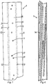
- the strip 1 shown in FIG. 1 consists of cardboard, openings 11 being spaced apart being punched in a wide longitudinal surface 6. Two rows of openings 17, 18 are provided, the distances between the openings in the rows being different.
- the fold edges 2, 3, 4, 5, which are preferably prefolded, run in the longitudinal direction.
- the lateral strip sections 9, 10 preferably have dimensions such that they overlap when folded. But they can also be designed so that they only or not even meet.
- the dimensions of the strip in the longitudinal direction are arbitrary per se. A length of about 130 cm has proven to be suitable.
- the width of the wide longitudinal surfaces is essentially determined by the amount of reinforcing steel embedded in the device and is preferably 6 cm.
- the width of the narrow longitudinal surfaces 12, 13 is measured by the desired internal distance, which should preferably correspond to the thickness of the reinforcing steel 8.
- the openings 11 also preferably correspond to the strength of the reinforcing steels 8. Their spacing and their arrangement are determined by the desired reinforcement.
- the reinforcement steel used generally has a diameter between 6 and 12 mm. Steels with 8 and 10 mm are preferred.
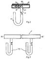
- connection areas 14 of the reinforcing steel 8 are embedded in the device, while the anchoring areas 15 of the reinforcing steel 8 are guided through the openings 11 and protrude.
- the length of the connection areas 14 is usually 30 to 60 cm, often 45 cm.
- the shape of the anchoring areas can be any.
- the length of the anchoring parts 15 is usually 5 to 20 cm.
- the anchoring part is designed as a bracket 19.
- the connection areas can be accommodated together in one device.
- the device is preferably closed by gluing. Sealing with adhesive strips has proven to be particularly simple and suitable.
- FIG. 3 shows a side view of the device in the folded state.
- the anchoring areas 15 of the reinforcing steels 8 protrude from the folded strip 1.
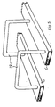
- connection areas 14 of the reinforcing steels 8 shows a possible arrangement of the connection areas 14 of the reinforcing steels 8.
- the arrangement is in itself arbitrary and depends on the number and length of the reinforcing steel.
- the device according to the invention is used in a manner known per se, for which reference can be made, for example, to the explanations in European Patent 0 024 697.
Landscapes
- Engineering & Computer Science (AREA)
- Architecture (AREA)
- Mechanical Engineering (AREA)
- Civil Engineering (AREA)
- Structural Engineering (AREA)
- Forms Removed On Construction Sites Or Auxiliary Members Thereof (AREA)
- Spinning Or Twisting Of Yarns (AREA)
- Liquid Developers In Electrophotography (AREA)
- Measuring Pulse, Heart Rate, Blood Pressure Or Blood Flow (AREA)
- Discharge Heating (AREA)
- Heat Treatment Of Strip Materials And Filament Materials (AREA)
Claims (4)
Priority Applications (1)
| Application Number | Priority Date | Filing Date | Title |
|---|---|---|---|
| AT85100954T ATE48867T1 (de) | 1984-02-10 | 1985-01-30 | Vorrichtung zur verwahrung von bewehrungsstaehlen. |
Applications Claiming Priority (2)
| Application Number | Priority Date | Filing Date | Title |
|---|---|---|---|
| DE3404837 | 1984-02-10 | ||
| DE3404837A DE3404837C2 (de) | 1984-02-10 | 1984-02-10 | Vorrichtung zur Verwahrung von Bewehrungsstählen |
Publications (3)
| Publication Number | Publication Date |
|---|---|
| EP0152015A2 EP0152015A2 (fr) | 1985-08-21 |
| EP0152015A3 EP0152015A3 (en) | 1986-08-27 |
| EP0152015B1 true EP0152015B1 (fr) | 1989-12-20 |
Family
ID=6227405
Family Applications (1)
| Application Number | Title | Priority Date | Filing Date |
|---|---|---|---|
| EP85100954A Expired EP0152015B1 (fr) | 1984-02-10 | 1985-01-30 | Dispositif pour loger des barres d'armatures |
Country Status (4)
| Country | Link |
|---|---|
| EP (1) | EP0152015B1 (fr) |
| AT (2) | AT390102B (fr) |
| DE (2) | DE3404837C2 (fr) |
| FI (1) | FI850544A7 (fr) |
Cited By (3)
| Publication number | Priority date | Publication date | Assignee | Title |
|---|---|---|---|---|
| EP0457315A1 (fr) * | 1990-05-17 | 1991-11-21 | Max Frank GmbH & Co. KG | Raccord pour armature et construction en béton avec un tel raccord |
| FR2694954A1 (fr) * | 1992-08-18 | 1994-02-25 | Mure Ets | Caisson pour la mise en attente d'armatures de liaison entre deux parties d'ouvrage en béton contigues et coulées l'une après l'autre. |
| AU2009238356B2 (en) * | 2008-11-21 | 2016-08-18 | Illinois Tool Works Inc. | A Box for Form Work |
Families Citing this family (1)
| Publication number | Priority date | Publication date | Assignee | Title |
|---|---|---|---|---|
| FR2796095B1 (fr) | 1999-07-08 | 2001-09-07 | Cogito | Caisson de boite d'attente et boite d'attente integrant un tel caisson |
Family Cites Families (13)
| Publication number | Priority date | Publication date | Assignee | Title |
|---|---|---|---|---|
| FR1227400A (fr) * | 1959-03-05 | 1960-08-19 | Dispositif assurant la liaison entre des éléments de construction | |
| CH627811A5 (de) * | 1978-12-18 | 1982-01-29 | Brechbuehler Fritz | Armierungseisenhalter zur verwendung bei anschlussbetonierungen. |
| CH637178A5 (en) * | 1979-04-09 | 1983-07-15 | Fritz Brechbuehler | Anchoring device for attaching to a shuttering of a prefabricated concrete unit |
| CH626676A5 (fr) * | 1979-05-01 | 1981-11-30 | Witschi H | |
| DE7924049U1 (de) * | 1979-08-23 | 1979-11-22 | Sigma Bauelemente Gmbh | Vorrichtung zum Verwahren von Bewehrungsstaehlen |
| CH641518A5 (en) * | 1979-10-15 | 1984-02-29 | Hp System Ag | Process for producing an anchoring used as a reinforced-concrete connection |
| DE8101897U1 (de) * | 1981-01-27 | 1982-06-16 | Sigma Bauelemente Gmbh, 4800 Bielefeld | "vorrichtung zum verwahren von bewehrungsstaehlen" |
| DE3134253A1 (de) * | 1981-08-29 | 1983-03-10 | Reent 4970 Bad Oeynhausen Obernolte | "vorrichtung zum verwahren von bewehrungsstaehlen" |
| DE8131746U1 (de) * | 1981-10-30 | 1982-03-11 | Max Frank Gmbh & Co Kg, 8441 Leiblfing | Vorrichtung zum verwahren und halten von verbindungsstaehlen fuer betonbauteile |
| FI62888C (fi) * | 1981-12-15 | 1983-03-10 | Rake Oy | Foertillverkat betongarmeringselement och foerfarande vid tillverkning av armeringsanslutningar |
| DE8205197U1 (de) * | 1982-02-25 | 1982-06-16 | Dausend, Hans Werner, 5600 Wuppertal | Verwahrgehaeuse fuer wandanschluss-bewehrungsstaehle |
| DE3211563C2 (de) * | 1982-02-25 | 1985-03-28 | Bernd 6451 Mainhausen Reichelt | Schalungs- und Verwahrungselement |
| AT376267B (de) * | 1982-12-13 | 1984-10-25 | Avi Alpenlaendische Vered | Verbindungsteil fuer zwei stahlbetonbauelemente |
-
1984
- 1984-02-10 DE DE3404837A patent/DE3404837C2/de not_active Expired
- 1984-04-20 AT AT0133984A patent/AT390102B/de not_active IP Right Cessation
-
1985
- 1985-01-30 DE DE8585100954T patent/DE3574889D1/de not_active Expired - Lifetime
- 1985-01-30 EP EP85100954A patent/EP0152015B1/fr not_active Expired
- 1985-01-30 AT AT85100954T patent/ATE48867T1/de not_active IP Right Cessation
- 1985-02-08 FI FI850544A patent/FI850544A7/fi not_active Application Discontinuation
Cited By (5)
| Publication number | Priority date | Publication date | Assignee | Title |
|---|---|---|---|---|
| EP0457315A1 (fr) * | 1990-05-17 | 1991-11-21 | Max Frank GmbH & Co. KG | Raccord pour armature et construction en béton avec un tel raccord |
| US5341616A (en) * | 1990-05-17 | 1994-08-30 | Max Frank Gmbh & Co Kg | Concrete insert element and concrete structure having at least one concrete insert element |
| FR2694954A1 (fr) * | 1992-08-18 | 1994-02-25 | Mure Ets | Caisson pour la mise en attente d'armatures de liaison entre deux parties d'ouvrage en béton contigues et coulées l'une après l'autre. |
| AU2009238356B2 (en) * | 2008-11-21 | 2016-08-18 | Illinois Tool Works Inc. | A Box for Form Work |
| AU2009238356C1 (en) * | 2008-11-21 | 2017-01-19 | Illinois Tool Works Inc. | A Box for Form Work |
Also Published As
| Publication number | Publication date |
|---|---|
| ATA133984A (de) | 1989-08-15 |
| DE3404837A1 (de) | 1985-08-22 |
| AT390102B (de) | 1990-03-26 |
| EP0152015A3 (en) | 1986-08-27 |
| FI850544L (fi) | 1985-08-11 |
| FI850544A0 (fi) | 1985-02-08 |
| DE3574889D1 (de) | 1990-01-25 |
| DE3404837C2 (de) | 1986-09-25 |
| FI850544A7 (fi) | 1985-08-11 |
| ATE48867T1 (de) | 1990-01-15 |
| EP0152015A2 (fr) | 1985-08-21 |
Similar Documents
| Publication | Publication Date | Title |
|---|---|---|
| EP0274085B1 (fr) | Pince-papier en matière plastique | |
| DE1750713B2 (de) | Verbindung von Holzbauteilen einer Baukonstruktion mit zwei Krallenplatten | |
| DE2827950A1 (de) | Hohlprofilstab, insbesondere fuer tor- oder zaunpfosten | |
| DE2907656C2 (fr) | ||
| DE3238312C1 (de) | Kantenschutzband | |
| DE2708489B2 (de) | Riemenverbinder | |
| DE3404837C2 (de) | Vorrichtung zur Verwahrung von Bewehrungsstählen | |
| DE3127087A1 (de) | "vorrichtung zum verwahren von bewehrungsstaehlen" | |
| DE2923903C2 (fr) | ||
| DE2613522B2 (de) | Fur Holzverbindungen bestimmte Krallenplatte | |
| CH676567A5 (fr) | ||
| DE2650181B2 (de) | Krallenplatte | |
| DE1534957B1 (de) | Schalungsrost fuer Betonwaende od.dgl. | |
| DE2843457C2 (de) | Wandbekleidung | |
| EP0397293B1 (fr) | Rail de fixation pour tôles à ondes trapézoidales pour la technique de la construction | |
| DE202019103391U1 (de) | Spannvorrichtung für eine Eckverschalung | |
| DE29519544U1 (de) | Sollriß-Fugenschiene für Betonbauten | |
| DE9109283U1 (de) | Schalung für den Betonbau sowie Vorrichtung zum Herstellen der Schalung | |
| DE2065276C3 (de) | Längsstrahlende Antenne mit einem Längsträger und darauf angeordneten Antenne nelementen | |
| DE3623361A1 (de) | Webblatt | |
| DE2128553B2 (de) | Anordnung zum Befestigen eines Kupplungsstucks fur Betonschalungen | |
| DE1484328C (de) | Mehrschichtiges Bauelement | |
| DE102024121610A1 (de) | Mehrteiliges Schalungselement zum Erstellen einer Arbeitsfuge | |
| DE2457523B1 (de) | Schalungszuganker mit abstandhalter fuer einander gegenueberstehende schalungswaende | |
| DE1908368A1 (de) | Matrize fuer Eintreibgeraete von Befestigungsmitteln |
Legal Events
| Date | Code | Title | Description |
|---|---|---|---|
| PUAI | Public reference made under article 153(3) epc to a published international application that has entered the european phase |
Free format text: ORIGINAL CODE: 0009012 |
|
| AK | Designated contracting states |
Designated state(s): AT BE CH DE FR GB IT LI LU NL SE |
|
| PUAL | Search report despatched |
Free format text: ORIGINAL CODE: 0009013 |
|
| AK | Designated contracting states |
Kind code of ref document: A3 Designated state(s): AT BE CH DE FR GB IT LI LU NL SE |
|
| 17P | Request for examination filed |
Effective date: 19870121 |
|
| 17Q | First examination report despatched |
Effective date: 19871207 |
|
| GRAA | (expected) grant |
Free format text: ORIGINAL CODE: 0009210 |
|
| AK | Designated contracting states |
Kind code of ref document: B1 Designated state(s): AT BE CH DE FR GB IT LI LU NL SE |
|
| REF | Corresponds to: |
Ref document number: 48867 Country of ref document: AT Date of ref document: 19900115 Kind code of ref document: T |
|
| GBT | Gb: translation of ep patent filed (gb section 77(6)(a)/1977) | ||
| REF | Corresponds to: |
Ref document number: 3574889 Country of ref document: DE Date of ref document: 19900125 |
|
| ET | Fr: translation filed | ||
| ITF | It: translation for a ep patent filed | ||
| PGFP | Annual fee paid to national office [announced via postgrant information from national office to epo] |
Ref country code: AT Payment date: 19900627 Year of fee payment: 6 |
|
| PG25 | Lapsed in a contracting state [announced via postgrant information from national office to epo] |
Ref country code: DE Effective date: 19901002 |
|
| PLBE | No opposition filed within time limit |
Free format text: ORIGINAL CODE: 0009261 |
|
| STAA | Information on the status of an ep patent application or granted ep patent |
Free format text: STATUS: NO OPPOSITION FILED WITHIN TIME LIMIT |
|
| 26N | No opposition filed | ||
| PG25 | Lapsed in a contracting state [announced via postgrant information from national office to epo] |
Ref country code: AT Effective date: 19910130 |
|
| ITTA | It: last paid annual fee | ||
| EPTA | Lu: last paid annual fee | ||
| EAL | Se: european patent in force in sweden |
Ref document number: 85100954.8 |
|
| PGFP | Annual fee paid to national office [announced via postgrant information from national office to epo] |
Ref country code: GB Payment date: 19970113 Year of fee payment: 13 |
|
| PGFP | Annual fee paid to national office [announced via postgrant information from national office to epo] |
Ref country code: FR Payment date: 19970120 Year of fee payment: 13 |
|
| PGFP | Annual fee paid to national office [announced via postgrant information from national office to epo] |
Ref country code: SE Payment date: 19970123 Year of fee payment: 13 Ref country code: BE Payment date: 19970123 Year of fee payment: 13 |
|
| PGFP | Annual fee paid to national office [announced via postgrant information from national office to epo] |
Ref country code: CH Payment date: 19970128 Year of fee payment: 13 |
|
| PGFP | Annual fee paid to national office [announced via postgrant information from national office to epo] |
Ref country code: NL Payment date: 19970131 Year of fee payment: 13 |
|
| PGFP | Annual fee paid to national office [announced via postgrant information from national office to epo] |
Ref country code: LU Payment date: 19970709 Year of fee payment: 13 |
|
| PG25 | Lapsed in a contracting state [announced via postgrant information from national office to epo] |
Ref country code: LU Free format text: LAPSE BECAUSE OF NON-PAYMENT OF DUE FEES Effective date: 19980130 Ref country code: GB Free format text: LAPSE BECAUSE OF NON-PAYMENT OF DUE FEES Effective date: 19980130 |
|
| PG25 | Lapsed in a contracting state [announced via postgrant information from national office to epo] |
Ref country code: SE Free format text: LAPSE BECAUSE OF NON-PAYMENT OF DUE FEES Effective date: 19980131 Ref country code: LI Free format text: LAPSE BECAUSE OF NON-PAYMENT OF DUE FEES Effective date: 19980131 Ref country code: FR Free format text: THE PATENT HAS BEEN ANNULLED BY A DECISION OF A NATIONAL AUTHORITY Effective date: 19980131 Ref country code: CH Free format text: LAPSE BECAUSE OF NON-PAYMENT OF DUE FEES Effective date: 19980131 Ref country code: BE Free format text: LAPSE BECAUSE OF NON-PAYMENT OF DUE FEES Effective date: 19980131 |
|
| BERE | Be: lapsed |
Owner name: BLASY ROLF Effective date: 19980131 Owner name: FUHS JOSEH Effective date: 19980131 |
|
| PG25 | Lapsed in a contracting state [announced via postgrant information from national office to epo] |
Ref country code: NL Free format text: LAPSE BECAUSE OF NON-PAYMENT OF DUE FEES Effective date: 19980801 |
|
| REG | Reference to a national code |
Ref country code: CH Ref legal event code: PL |
|
| GBPC | Gb: european patent ceased through non-payment of renewal fee |
Effective date: 19980130 |
|
| NLV4 | Nl: lapsed or anulled due to non-payment of the annual fee |
Effective date: 19980801 |
|
| EUG | Se: european patent has lapsed |
Ref document number: 85100954.8 |
|
| REG | Reference to a national code |
Ref country code: FR Ref legal event code: ST |