EP0152020A2 - Méthode et appareil pour couper des pièces planes, par exemple des plaques métalliques - Google Patents
Méthode et appareil pour couper des pièces planes, par exemple des plaques métalliques Download PDFInfo
- Publication number
- EP0152020A2 EP0152020A2 EP85101001A EP85101001A EP0152020A2 EP 0152020 A2 EP0152020 A2 EP 0152020A2 EP 85101001 A EP85101001 A EP 85101001A EP 85101001 A EP85101001 A EP 85101001A EP 0152020 A2 EP0152020 A2 EP 0152020A2
- Authority
- EP
- European Patent Office
- Prior art keywords
- workpiece
- knives
- knife
- cutting
- moved
- Prior art date
- Legal status (The legal status is an assumption and is not a legal conclusion. Google has not performed a legal analysis and makes no representation as to the accuracy of the status listed.)
- Granted
Links
- 238000005520 cutting process Methods 0.000 title claims abstract description 91
- 238000000034 method Methods 0.000 title claims abstract description 27
- 239000002184 metal Substances 0.000 title abstract description 9
- 230000000737 periodic effect Effects 0.000 claims description 4
- 238000007654 immersion Methods 0.000 claims description 3
- 230000000149 penetrating effect Effects 0.000 claims 1
- 230000000284 resting effect Effects 0.000 description 2
- 239000000725 suspension Substances 0.000 description 2
- 230000001419 dependent effect Effects 0.000 description 1
- 238000011161 development Methods 0.000 description 1
- 230000018109 developmental process Effects 0.000 description 1
- 239000013013 elastic material Substances 0.000 description 1
- 230000001404 mediated effect Effects 0.000 description 1
- 238000005096 rolling process Methods 0.000 description 1
- 230000001360 synchronised effect Effects 0.000 description 1
Images
Classifications
-
- B—PERFORMING OPERATIONS; TRANSPORTING
- B23—MACHINE TOOLS; METAL-WORKING NOT OTHERWISE PROVIDED FOR
- B23D—PLANING; SLOTTING; SHEARING; BROACHING; SAWING; FILING; SCRAPING; LIKE OPERATIONS FOR WORKING METAL BY REMOVING MATERIAL, NOT OTHERWISE PROVIDED FOR
- B23D15/00—Shearing machines or shearing devices cutting by blades which move parallel to themselves
- B23D15/06—Sheet shears
-
- B—PERFORMING OPERATIONS; TRANSPORTING
- B23—MACHINE TOOLS; METAL-WORKING NOT OTHERWISE PROVIDED FOR
- B23D—PLANING; SLOTTING; SHEARING; BROACHING; SAWING; FILING; SCRAPING; LIKE OPERATIONS FOR WORKING METAL BY REMOVING MATERIAL, NOT OTHERWISE PROVIDED FOR
- B23D15/00—Shearing machines or shearing devices cutting by blades which move parallel to themselves
- B23D15/02—Shearing machines or shearing devices cutting by blades which move parallel to themselves having both upper and lower moving blades
-
- B—PERFORMING OPERATIONS; TRANSPORTING
- B23—MACHINE TOOLS; METAL-WORKING NOT OTHERWISE PROVIDED FOR
- B23D—PLANING; SLOTTING; SHEARING; BROACHING; SAWING; FILING; SCRAPING; LIKE OPERATIONS FOR WORKING METAL BY REMOVING MATERIAL, NOT OTHERWISE PROVIDED FOR
- B23D31/00—Shearing machines or shearing devices covered by none or more than one of the groups B23D15/00 - B23D29/00; Combinations of shearing machines
Definitions
- the invention relates to a method and an apparatus for separating flat workpieces, for example sheet metal, with a pair of separating cutting knives, which are periodically moved towards and away from one another with their cutting edges interposed between the workpiece to be cut and the mutual overlap.
- the cutting direction of the two knives which are to be moved towards one another is always the longitudinal direction of their cutting edges. Since in the known methods and devices the cutting edges of the knives remain unchanged in their orientation, when cutting curves, arches or corners the workpiece must be rotated in such a way that the line of the new partial cut to be made on this workpiece extends parallel to the knife cutting edges.
- the invention is therefore based on the object in a method or a device of the type mentioned not to have to rotate the workpiece in the direction desired for the respective next partial cut in relation to the knives in order to cut a curve. to allow computer-controlled automatic feed of the workpiece through the device.
- the workpiece is moved relative to the knives substantially without changing its orientation in a coordinate system in the direction of the desired cutting line and in that the knives with their cutting edge are perpendicular to the surface of the workpiece to be cut (cutting plane)
- the axis should be rotated in the respective cutting direction required for the next separating cut, whereby the setting of the feed direction of the guide for feeding the workpiece according to the desired cutting line and the setting of the knives with their cutting edges are appropriately coupled in this cutting direction.
- the procedure is such that, by coordinate guidance of the workpiece, the front cutting edges of the knives, with which they plunge into the workpiece ahead, are in any desired cutting direction at the location of the coordinate start values for the new partial cut to be made and the cutting length is in each case continues in the direction of the next coordinate values.
- the knives are rotated in the respective new cutting direction if at least one, expediently, however, both knives are moved out of the workpiece during their periodic movement towards and away from one another or if they have emerged from their mutual overlap.
- the above-mentioned procedural measures ensure that every small part cut is made completely new and independent of the previous partial cut on the workpiece, so that any cutting line, including sharp-angled corner cuts without rounding or sharp curves with the smallest curve radius, is possible, whereby the workpiece to be cut can be pushed towards the knives without any tension.
- a free contactless feed movement of the workpiece relative to the knives is also possible. This feed movement can be controlled so that it only occurs when the knives are pulled out of the workpiece.
- the method according to the invention ensures completely waste-free separating cuts, which can be carried out at a high cutting speed that parts that fit into one another practically without play can be produced with a single cut.
- a different length of the cuts is obtained depending on the depth of overlap of the knives, so that with a correspondingly small overlap it is possible to make a faceted cut sequence only with cutting lengths of approx. 1 mm, which results in an almost homogeneous arc or circular shape of the cutting line to be produced.
- the period of time during which at least one knife is moved out of the workpiece is longer than that during which this knife overlaps with the other knife during a periodic movement towards and away from one another Workpiece is immersed.
- the depth of overlap of the knives is advantageously kept smaller the smaller the curve radius is in order to obtain curve cuts that are as continuous as possible.
- a device which, according to the invention, has a guide for the movement of the workpiece relative to the knives essentially without changing its orientation in a coordinate system, both knives with their mutually parallel cutting edges around a surface of the workpiece to be cut (cutting plane ) vertical or substantially vertical axis can be rotated, which passes through the tip or the area of the cutting edges of the knives, with which they first dip into the workpiece when they are moved towards one another.
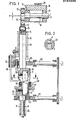
- the two cutting knives 1, 2 are arranged vertically one above the other and provided with cutting edges 3, 4 which are oblique to one another.
- Each of these knives is stored in its own knife holder 5, 6, which are fastened at the end of each shaft 7, 8.
- the shaft 8 for the lower knife 2 is rotatable in a cylindrical bearing 9, but is non-displaceable in the axial direction
- the shaft 7 of the upper knife 1 forms a piston which can be moved up and down axially in a cylindrical bearing 10 and which the upper knife has to carry out of the cutting according to the invention required up and down movement relative to the lower knife mediated.
- the knife holder 5 for the upper knife is rotatably mounted about the axis 25.
- the tips of the the two knives have a distance from one another which corresponds approximately or at least to the thickness of the workpiece to be cut, for example a metal sheet or the like.
- an eccentric disc 11 is used, on which a crank part 13 is seated via a ball or roller bearing 12 and which is connected with its crank arm 14 via a crank pin 15 to the upper end of the shaft 7.
- the eccentric disc 11 is eccentrically seated on an eccentric shaft 16 driven by a motor (not shown).
- the eccentric shaft 16 is in turn seated via ball or roller bearings 17 in a screw eccentric 18, which can be adjusted in its rotational position via a screw shaft 19.
- the height of the eccentric shaft 16 mounted in it can be changed by rotating the screw eccentric 18, as a result of which the depth of overlap of the two knives 1, 2 and the depth of immersion of the knife 1 in the workpiece to be cut can be adjusted.
- a worm wheel 20, 21 with associated worm 22, 23 is provided on each shaft 7, 8.
- the two screws are for a synchronous drive via a gearbox, a chain or another drive element, e.g. Toothed belt or the like. Forcibly coupled together.
- the lower worm wheel 21 is fixedly connected to the rotatable shaft 8, while the upper but rotatable but rotatable shaft 7 is not fixedly connected to the upper worm wheel 20 but projects loosely through it.
- at least one driver pin 24 is seated on this knife holder and can be moved axially up and down in the worm wheel 20 via a guide bushing (not shown in the drawing) is stored. This design ensures that the knife holder rotates with the worm wheel without the upward and downward movement of the knife holder on the shaft 7 being impeded.
- the knives 1, 2 are mounted in their knife holders 5, 6 so that their axis of rotation 25 lies in the vertical front edge 26 of the knives leading to the knife tip. This ensures that the front cut edges of the better form the starting coordinates of the cutting line in each cutting direction, the direction of the next partial cut being determined by the feed direction and the dependent rotary position of the knives, which can be predetermined by coordinate control.
- a support ring 27 made of elastic material and surrounding the lower knife 2 is used to support the workpiece to be cut in the area of the cutting knives during the cutting process.
- the top of this ring is provided with a wear-resistant metal cover 28, over which the workpiece to be cut can be advanced in relation to the knives in the desired cutting direction.
- the elasticity of this support ring 27 is dimensioned such that its support surface formed by the top of the metal cover 28 is at least as high or higher than the cutting tip of the lower knife 2 or the cutting plane 29 without the workpiece being loaded, with the workpiece resting thereon and vertically downward on this workpiece, however, the cutting pressure exerted by the upper knife 1 can be pressed with its support surface so far below the cutting plane 29 that the lower knife 2 is immersed in the workpiece.
- the elastically flexible support ring can also be formed by a rubber mat or by support springs having a support surface on its upper side.
- a hold-down arm 40 is provided for holding and guiding the workpiece on its upper side, against which the upper side of the workpiece can be supported and the height of which can be adjusted relative to the workpiece.
- the two knives 1, 2 can be pivoted back and forth slightly in the direction of the workpiece feed about horizontal axes 30, 31 in the knife holders 5, 6.
- they are mounted on their front and rear edges as well as on their top edge with corresponding play in their knife holders.
- the front edges 26 of the knives are loaded via spring elements 32 mounted in the knife holders in such a way that the knives are pressed into their vertical starting pivot position shown in FIG. 1, which is fixed by abutting the rear edges of the knives against the knife holder.
- the knives can follow the workpiece with their cutting edges against the pressure of the spring elements 32 until they are moved out of the workpiece again at the end of their cutting process. whereupon they are moved back into their starting pivot position by the spring elements.
- the spring force of the spring elements 32 must be such that the possibility of the knives pivoting out about their axes 30 and 31 does not endanger the immersion of the knives with their cutting edges in the workpiece.
- the cutting knives 1, 2 are not pivoted laterally about horizontal axes, as in the embodiment shown in the drawing, but are rigidly or fixedly mounted in the knife holders 5, 6, for example by a clamping ring, a stopping of the workpiece feed is necessary during the period while the knife 1,2 immerse in the workpiece.
- the workpiece can only be fed as long as the knives with their cutting edges are outside the workpiece. This results in a jerky workpiece feed, which must be controlled in accordance with the up and down movement of the knives.
- a hydraulic drive can also be used for the up and down movement of the upper rotary shaft 7 for the upper knife 1.
- the cutting edges 3 ', 4' of the two knives 1, 2 are curved concavely with respect to the cutting plane 29.
- this results in the knives rolling down into the workpiece as it is advanced during the cutting process.
- a concavely curved, that is to say hollow-ground, cutting edge may also be expedient under certain circumstances, in particular when separating cuts are to be made with tight curves or sharp corners.
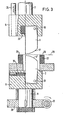
- the embodiment shown in FIG. 3 is the same as that in FIGS. 1 and 2 with the exception that the spring element for the upper knife 1 is formed by a rubber stopper 33.
- the hold-down arm 30 is omitted for reasons of clarity.
- the knife holder 6 for the lower knife 2 is rotatably mounted on the shaft 7 ', which can be moved up and down in a corresponding cylindrical bearing 10' like a piston.
- Both shafts 7, 7 ' are connected at their ends facing away from the knives 1, 2 with an eccentric disk 11, 11', on which a crank part 13, 13 'is seated via a ball or roller bearing 12, 12', which has a crank arm 14, 14 'is connected to the upper end of the shaft 7, 7' via a crank pin 15, 15 '.
- the eccentric disks 11, 12 sit eccentrically around the dimension x on an eccentric shaft 16, 16 'driven by a motor, not shown, which in turn is mounted on the machine frame via ball or roller bearings 17, 17'.
- the up and down movement of both separating knives 1, 2 is thus generated in this exemplary embodiment in the same way as in the upper separating knife 1 of the exemplary embodiment according to FIGS. 1 to 3.
- the rotary movement of the separating knives 1, 2 also takes place in this exemplary embodiment in the same way as in the upper knife of the exemplary embodiment according to FIGS. 1 and 2, that is to say via worm wheels 20, 21 driven by screws 22, 23, the rotation of which takes place via driving pins 24, 24 ' the knife holder 5,6 is transferred.
- the cutting knives are not tiltably mounted in the knife holders via tilting axes, but are replaceable in the knife holders 5,6, for example attached by clamping devices.
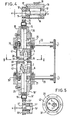
- the two separating knives 1, 2 protrude through openings 34, 35 in turntables 36, 37 which are rotatably supported in ball bearings 38, 39 in suspensions 41, 42, which suspensions are fastened to the machine frame.
- the turntables also rotate about the axis 25.
- the turntables serve as abutments for the sheet to be cut between them.
- pulling the separating knife 1, 2 out of the sheet metal they support the sheet metal on both sides, so that the knife cannot pull it along. This encourages the knives to slide out of the separating slot created in the sheet metal, without entanglement or tension occurring in it. This happens regardless of the rotary position of the knives, since the turntables can be rotated with the knives.
Landscapes
- Engineering & Computer Science (AREA)
- Mechanical Engineering (AREA)
- Shearing Machines (AREA)
- Details Of Cutting Devices (AREA)
- Control Of Cutting Processes (AREA)
- Manufacture Of Wood Veneers (AREA)
- Perforating, Stamping-Out Or Severing By Means Other Than Cutting (AREA)
Priority Applications (1)
| Application Number | Priority Date | Filing Date | Title |
|---|---|---|---|
| AT85101001T ATE51784T1 (de) | 1984-02-07 | 1985-01-31 | Verfahren und vorrichtung zum trennschneiden von flaechigen werkstuecken, beispielsweise blechen. |
Applications Claiming Priority (2)
| Application Number | Priority Date | Filing Date | Title |
|---|---|---|---|
| DE19843404234 DE3404234A1 (de) | 1984-02-07 | 1984-02-07 | Verfahren und vorrichtung zum trennschneiden von flaechigen werkstuecken, beispielsweise blechen |
| DE3404234 | 1984-02-07 |
Publications (3)
| Publication Number | Publication Date |
|---|---|
| EP0152020A2 true EP0152020A2 (fr) | 1985-08-21 |
| EP0152020A3 EP0152020A3 (en) | 1986-10-22 |
| EP0152020B1 EP0152020B1 (fr) | 1990-04-11 |
Family
ID=6226987
Family Applications (1)
| Application Number | Title | Priority Date | Filing Date |
|---|---|---|---|
| EP85101001A Expired - Lifetime EP0152020B1 (fr) | 1984-02-07 | 1985-01-31 | Méthode et appareil pour couper des pièces planes, par exemple des plaques métalliques |
Country Status (3)
| Country | Link |
|---|---|
| EP (1) | EP0152020B1 (fr) |
| AT (1) | ATE51784T1 (fr) |
| DE (2) | DE3404234A1 (fr) |
Cited By (4)
| Publication number | Priority date | Publication date | Assignee | Title |
|---|---|---|---|---|
| EP1074324A1 (fr) * | 1999-07-27 | 2001-02-07 | Mabi Ag | Dispositif pour couper des feuilles métalliques |
| CN113547558A (zh) * | 2021-07-13 | 2021-10-26 | 郑州中顺智能设备有限公司 | 一种裁切装置 |
| CN114833396A (zh) * | 2022-03-29 | 2022-08-02 | 新疆八钢金属制品有限公司 | 一种钢管管端保护器出料导向装置 |
| CN119973214A (zh) * | 2025-03-31 | 2025-05-13 | 航天科工火箭技术有限公司 | 一种异形金属管切割装置及使用方法 |
Families Citing this family (1)
| Publication number | Priority date | Publication date | Assignee | Title |
|---|---|---|---|---|
| RU2121414C1 (ru) * | 1997-06-25 | 1998-11-10 | Открытое акционерное общество "Уральский завод тяжелого машиностроения" | Способ резки горячего проката |
Family Cites Families (4)
| Publication number | Priority date | Publication date | Assignee | Title |
|---|---|---|---|---|
| BE462011A (fr) * | ||||
| US3830122A (en) * | 1973-03-26 | 1974-08-20 | Gerber Garment Technology Inc | Apparatus for dispensing a liquid onto a tool |
| DE2717508A1 (de) * | 1977-04-20 | 1978-10-26 | Potomac Applied Mechanics | Verfahren und vorrichtung zum schneiden von blech |
| GB1535815A (en) * | 1977-06-20 | 1978-12-13 | Bowman H | Cropping machine |
-
1984
- 1984-02-07 DE DE19843404234 patent/DE3404234A1/de not_active Withdrawn
-
1985
- 1985-01-31 DE DE8585101001T patent/DE3577051D1/de not_active Expired - Lifetime
- 1985-01-31 AT AT85101001T patent/ATE51784T1/de active
- 1985-01-31 EP EP85101001A patent/EP0152020B1/fr not_active Expired - Lifetime
Cited By (4)
| Publication number | Priority date | Publication date | Assignee | Title |
|---|---|---|---|---|
| EP1074324A1 (fr) * | 1999-07-27 | 2001-02-07 | Mabi Ag | Dispositif pour couper des feuilles métalliques |
| CN113547558A (zh) * | 2021-07-13 | 2021-10-26 | 郑州中顺智能设备有限公司 | 一种裁切装置 |
| CN114833396A (zh) * | 2022-03-29 | 2022-08-02 | 新疆八钢金属制品有限公司 | 一种钢管管端保护器出料导向装置 |
| CN119973214A (zh) * | 2025-03-31 | 2025-05-13 | 航天科工火箭技术有限公司 | 一种异形金属管切割装置及使用方法 |
Also Published As
| Publication number | Publication date |
|---|---|
| DE3577051D1 (de) | 1990-05-17 |
| DE3404234A1 (de) | 1985-08-08 |
| EP0152020B1 (fr) | 1990-04-11 |
| EP0152020A3 (en) | 1986-10-22 |
| ATE51784T1 (de) | 1990-04-15 |
Similar Documents
| Publication | Publication Date | Title |
|---|---|---|
| EP0321590B1 (fr) | Méthode et appareil pour la production d'une matrice d'estampage à bord de coupe aigu | |
| CH659203A5 (de) | Scherschneidemaschine. | |
| DE19638990A1 (de) | Schneidemaschine | |
| DE19516953B4 (de) | Vorrichtung zum Seitenschneiden von Papier | |
| DE2507449A1 (de) | Maschinenschere | |
| DE2826476C2 (fr) | ||
| DE1511269B1 (de) | Vorrichtung zum radialen Schneiden rollenfoermiger Koerper | |
| DE1502998A1 (de) | Schrottzerkleinerer fuer Seitenbesaeumscheren | |
| DE69107375T2 (de) | Sägeblattschärfapparat. | |
| EP0152020B1 (fr) | Méthode et appareil pour couper des pièces planes, par exemple des plaques métalliques | |
| DE3415438A1 (de) | Eindrueckungsfreie rohrschneidevorrichtung | |
| DE3145599C2 (de) | Lederspaltmaschine | |
| DE2422815B2 (de) | Schneideinrichtung | |
| DE304676C (fr) | ||
| DE3615381C2 (de) | Fuehrungsvorrichtung fuer den messerbalken einer schere zur blechbearbeitung | |
| DE3022922A1 (de) | Blechschere | |
| DE2341671A1 (de) | Elektroerodiermaschine | |
| DE3040447C1 (de) | Rollentisch fuer Blechbearbeitungsmaschinen | |
| DE2700062A1 (de) | Schlauch-zusammenfuegmaschine | |
| DE2911576A1 (de) | Schnellaufende maschine zum kaltschmieden von schrauben, nieten u.ae. hartwaren | |
| EP0076526B1 (fr) | Dispositif de coupage | |
| DE235786C (fr) | ||
| DE2526199A1 (de) | Schere zum schneiden von profilmaterial | |
| DE157599C (fr) | ||
| DE2717508A1 (de) | Verfahren und vorrichtung zum schneiden von blech |
Legal Events
| Date | Code | Title | Description |
|---|---|---|---|
| PUAI | Public reference made under article 153(3) epc to a published international application that has entered the european phase |
Free format text: ORIGINAL CODE: 0009012 |
|
| AK | Designated contracting states |
Designated state(s): AT BE CH DE FR GB IT LI LU NL SE |
|
| PUAL | Search report despatched |
Free format text: ORIGINAL CODE: 0009013 |
|
| AK | Designated contracting states |
Kind code of ref document: A3 Designated state(s): AT BE CH DE FR GB IT LI LU NL SE |
|
| 17P | Request for examination filed |
Effective date: 19870304 |
|
| 17Q | First examination report despatched |
Effective date: 19881028 |
|
| GRAA | (expected) grant |
Free format text: ORIGINAL CODE: 0009210 |
|
| AK | Designated contracting states |
Kind code of ref document: B1 Designated state(s): AT BE CH DE FR GB IT LI LU NL SE |
|
| REF | Corresponds to: |
Ref document number: 51784 Country of ref document: AT Date of ref document: 19900415 Kind code of ref document: T |
|
| ITF | It: translation for a ep patent filed | ||
| GBT | Gb: translation of ep patent filed (gb section 77(6)(a)/1977) | ||
| REF | Corresponds to: |
Ref document number: 3577051 Country of ref document: DE Date of ref document: 19900517 |
|
| ET | Fr: translation filed | ||
| PG25 | Lapsed in a contracting state [announced via postgrant information from national office to epo] |
Ref country code: LU Free format text: LAPSE BECAUSE OF NON-PAYMENT OF DUE FEES Effective date: 19910131 Ref country code: GB Effective date: 19910131 Ref country code: BE Effective date: 19910131 Ref country code: AT Effective date: 19910131 |
|
| PG25 | Lapsed in a contracting state [announced via postgrant information from national office to epo] |
Ref country code: SE Effective date: 19910201 |
|
| PLBE | No opposition filed within time limit |
Free format text: ORIGINAL CODE: 0009261 |
|
| STAA | Information on the status of an ep patent application or granted ep patent |
Free format text: STATUS: NO OPPOSITION FILED WITHIN TIME LIMIT |
|
| 26N | No opposition filed | ||
| PG25 | Lapsed in a contracting state [announced via postgrant information from national office to epo] |
Ref country code: NL Effective date: 19910801 |
|
| NLV4 | Nl: lapsed or anulled due to non-payment of the annual fee | ||
| GBPC | Gb: european patent ceased through non-payment of renewal fee | ||
| PG25 | Lapsed in a contracting state [announced via postgrant information from national office to epo] |
Ref country code: FR Effective date: 19910930 |
|
| PG25 | Lapsed in a contracting state [announced via postgrant information from national office to epo] |
Ref country code: DE Effective date: 19911001 |
|
| REG | Reference to a national code |
Ref country code: FR Ref legal event code: ST |
|
| EUG | Se: european patent has lapsed |
Ref document number: 85101001.7 Effective date: 19911008 |
|
| PGFP | Annual fee paid to national office [announced via postgrant information from national office to epo] |
Ref country code: CH Payment date: 19960122 Year of fee payment: 12 |
|
| PG25 | Lapsed in a contracting state [announced via postgrant information from national office to epo] |
Ref country code: LI Effective date: 19970131 Ref country code: CH Effective date: 19970131 |
|
| REG | Reference to a national code |
Ref country code: CH Ref legal event code: PL |