EP0152035A2 - Korsettstange - Google Patents
Korsettstange Download PDFInfo
- Publication number
- EP0152035A2 EP0152035A2 EP85101093A EP85101093A EP0152035A2 EP 0152035 A2 EP0152035 A2 EP 0152035A2 EP 85101093 A EP85101093 A EP 85101093A EP 85101093 A EP85101093 A EP 85101093A EP 0152035 A2 EP0152035 A2 EP 0152035A2
- Authority
- EP
- European Patent Office
- Prior art keywords
- corset
- rods
- rod
- sheathing material
- bar according
- Prior art date
- Legal status (The legal status is an assumption and is not a legal conclusion. Google has not performed a legal analysis and makes no representation as to the accuracy of the status listed.)
- Granted
Links
Images
Classifications
-
- A—HUMAN NECESSITIES
- A41—WEARING APPAREL
- A41C—CORSETS; BRASSIERES
- A41C1/00—Corsets or girdles
- A41C1/12—Component parts
- A41C1/14—Stays; Steels
- A41C1/18—Stays; Steels of built-up type
Definitions
- the invention relates to a corset rod for women's outer and lower clothing with a flat cross-section, consisting of a plastic-coated, spring-elastic reinforcement carrier made of a plurality of spring-elastic rods arranged in a plane parallel to one another with lateral spacing, the sheathing material connecting the rods filling the space to form a one-piece corset rod.
- corset rod of the type mentioned which consists of a plastic.
- This document claims to weave, act or braid the corset rod from monofilament plastic threads of various thicknesses.
- Such corset bars can be sewn onto a piece of clothing, but they do not have sufficient transverse rigidity and are relatively expensive to manufacture.
- the publication also proposes to inject the corset rod in one piece. According to the main claim, the required spring elasticity is determined by the choice of the cross-sectional profile and the dimensions of the corset rod.
- Such a corset bar is difficult to sew through and must therefore be accommodated in the cross-section corresponding pockets in the garment to be reinforced. There is also a risk of breakage with one-piece plastic corset rods.
- Profiled corset bars made of a solid plastic also push through the inside and outside of the garment, which is unsightly and uncomfortable.
- a one-piece corset rod which consists of rods arranged in parallel and connected to one another at the ends and is produced overall by injection molding.
- the rods are not covered by a space-filling sheathing material, but can be connected to one another with short connecting rods.
- the spring elasticity is significantly influenced by the choice of the cross-sectional profile in the middle area of the corset rod.
- Corset bars of this type therefore also have the disadvantages of profiled, one-piece molded corset bars.
- the invention has for its object to provide a corset rod of the type described above, which is particularly simple to manufacture and process, can be sewn through, in particular its entire length can be fastened by sewing through to the relevant garment, and one has suitable spring elasticity, transverse rigidity and breaking strength.
- the sheathing material be an investment material which adheres to the circumferential surfaces of the rods from a more flexible plastic than the rods.
- the invention is therefore based on the basic idea of arranging resilient rods in a plane parallel to one another with lateral spacing as reinforcement carriers and embedding them together in a relatively softer plastic, so that the resilient effects of the individual rods add up and the cross section of the corset rod is essentially determined by the covering material is.
- the resilient rods are made of a thermosetting plastic, in particular of polyester resin.
- Such rods made of polyester resin have preferred thicknesses between 0.8 and 1.2 mm.
- the cross-section of the rod can in principle be freely chosen with regard to its shape and cross-sectional area, in particular hollow rods can also be used, but it has been found that a cylindrical rod shape has the most favorable mechanical property values for corset rods, with relatively thicker rods made of a material of relatively high spring elasticity and thinner rods with fewer Spring elasticity is preferable because then the adhesion with the sheathing material and the carrying of the neighboring bars is improved. In the case of rods made of plastic, there is also a reduced risk of a sewing needle accidentally hitting a rod breaking off when such corset rods are sewn in the area between the rods.
- the sheathing material fills the spaces between the resilient rods such as webbed skins, but the corset rods in the area of these spaces can be the same thickness as in the area of the resilient rods.
- Thermoplastic materials are particularly suitable for sheathing material not only because of their mechanical properties, but also because of the simple possibility of sheathing the resilient rods in the endless extrusion process.
- Polyolefins are particularly suitable as the sheathing material because their property values can be varied to a large extent.
- polyethylenes have to be sewn through, in particular in connection with 0.9 to 1.0 mm thick cylindrical
- Rods made of polyester resin are found to be particularly suitable for the purpose of the invention.
- Such polyethylenes are readily available, for example, under the trade name "Lupolen”.
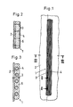
- an elongated corset bar 1 with a flat cross section is sewn onto a fabric base 2 with a thread 3.
- Five resilient rods 4 made of solid material made of polyester resin with a diameter of 0.9 to 1.0 mm serve as reinforcement members. These rods, which are arranged in a plane parallel to one another with a lateral spacing, are jointly embedded in a covering material 5, which consists of polyethylene and is applied to the polyester rods in an endless extrusion process.
- This sheathing material is sufficiently soft that it can be pierced by the sewing needle of a normal sewing machine. The sewing stitches are thus placed in the spaces between the bars 4 by the covering material 5 and either along the Corset bar in a single row or - as shown in Fig. 1 in the upper half - in a zigzag pattern, being careful when setting the stitch length that care should be taken not to pierce the polyester bars.
- the adhesion of the sheathing material 5 to the bars 4 increases the rigidity of the corset bar 1 in comparison to the rigidity of the bars alone because tensile or compressive forces arise above and below the bars 4 during bending.
Landscapes
- Engineering & Computer Science (AREA)
- Textile Engineering (AREA)
- Orthopedics, Nursing, And Contraception (AREA)
- Corsets Or Brassieres (AREA)
- Nitrogen And Oxygen Or Sulfur-Condensed Heterocyclic Ring Systems (AREA)
- Pharmaceuticals Containing Other Organic And Inorganic Compounds (AREA)
- Details Of Garments (AREA)
- Joining Of Building Structures In Genera (AREA)
Abstract
Description
- Die Erfindung betrifft eine Korsettstange für die Damenober-und Unterbekleidung mit flachem Querschnitt, bestehend aus änem kunststoffummantelten, federelastischen Verstärkungsträger aus mehreren, in einer Ebene parallel zueinander mit seitlichem Abstand angeordneten federelastischen Stäben, wobei das Ummantelungsmaterial die Stäbe zwischenraumfüllend unter Bildung einer einteiligen Korsettstange verbindet.
- Aus der DE-GM 18 12 212 ist eine Korsettstange der eingangs genannten Art bekannt, die aus einem Kunststoff besteht. In dieser Druckschrift wird beansprucht, die Korsettstange aus monofilen Kunststoffäden verschiedener Dicke zu weben, zu wirken oder zu flechten. Solche Korsettstangen können zwar an einem Kleidungsstück angenäht werden, haben jedoch keine ausreichende Quersteifigkeit und sind relativ aufwendig in der Herstellung. In der Druckschrift wird weiterhin vorgeschlagen, die Korsettstange einstückig zu spritzen. Gemäß dem Hauptanspruch wird dabei die erforderliche Federelastizität über die Wahl des Querschnitssprofils und die Abmessungen der Korsettstange festgelegt. Eine solche Korsettstange ist schwer durchnähbar und muß deshalb in ihrem Querschnitt entsprechenden Taschen in dem zu verstärkenden Kleidungsstück untergebracht werden. Auch besteht bei einstückigen Korsettstangen aus Kunststoff Bruchgefahr. Profilierte Korsettstangen aus einem festen Kunststoff drücken sich zudem am Kleidungsstück nach innen und nach außen durch, was unansehnlich und unbequem ist.
- Aus der GB-PS 10 72 281 ist eine einstückige Korsettstange bekannt, die aus parallel angeordneten und an den Enden miteinander verbundenen Stäben besteht und insgesamt im Spritzgußverfahren hergestellt wird. Die Stäbe sind nicht von einem zwischenraumfüllenden Ummantelungsmaterial umhüllt, können aber mit kurzen Verbindungsstäben untereinander verbunden sein. Die Federelastizität wird maßgeblich durch die Wahl des Querschnittsprofils im mittleren Bereich der Korsettstange beeinflußt. Korsettstangen dieser Bauart haben somit auch die bereits oben angeführten Nachteile profilierter, einstückig gespritzter Korsettstangen.
- Davon ausgehend liegt der Erfindung die Aufgabe zugrunde, eine Korsettstange der eingangs beschriebenen Art zu schaffen, die besonders einfach herzustellen und zu verarbeiten ist, durchnäht werden kann, wobei sie insbesondere ihrer gesamten Länge nach durch Durchnähen an dem betreffenden Kleidungsstück befestigbar ist, und die eine geeignete Federelastizität, Quersteifigkeit und Bruchfestigkeit hat.
- Zur technischen Lösung dieser Aufgabe wird vorgeschlagen, daß das Ummantelungsmaterial eine Einbettmasse, welche auf den Umfangsflächen der Stäbe allseitig haftet, aus einem nachgiebigeren Kunststoff als die Stäbe ist.
- Die Erfindung basiert also auf dem Grundgedanken, als Verstärkungsträger federelastische Stäbe in einer Ebene parallel zueinander mit seitlichem Abstand anzuordnen und diese gemeinsam in einen relativ weicheren Kunststoff einzubetten, so daß sich die federelastischen Wirkungen der Einzelstäbe addieren und der Querschnitt der Korsettstange im wesentlichen von Ummantelungsmaterial festgelegt ist.
- Bei einer praktischen Ausführungsform der Erfindung sind die federelastischen Stäbe aus einem duroplastischen Kunststoff, insbesondere aus Polyesterharz, hergestellt. Solche Stäbe aus Polyesterharz haben bevorzugte Dicken zwischen 0,8 und 1,2 mm.
- Der Stabquerschnitt kann hinsichtlich seiner Form und Querschnittsfläche grundsätzlich frei gewählt werden, insbesondere sind auch Hohlstäbe anwendbar, doch hat sich herausgestellt, daß eine zylindrische Stabform die für Korsettstangen günstigsten mechanischen Eigenschaftswerte aufweist, wobei relativ dickere Stäbe aus einem Material relativ großer Federelastizität dünneren Stäben mit geringerer Federelastizität vorzuziehen sind, weil dann die Haftung mit dem Ummantelungsmaterial und das Mittragen der benachbarten Stäbe verbessert wird. Bei Stäben aus Kunststoff veringert sich zudem die Gefahr, daß beim Durchnähen solcher Korsettstangen im Bereich zwischen den Stäben eine unbeabsichtigt auf einen Stab treffende Nähnadel abbricht.
- Das Ummantelungsmaterial füllt die Zwischenräume der federelastischen Stäbe wie Schwimmhäute aus, wobei die Korsettstangen aber im Bereich dieser Zwischenräume gleich dick wie im Bereich der federelastischen Stäbe sein können. Thermoplastische Kunststoffe eignen sich für Ummantelungsmaterial nicht nur wegen ihrer mechanischen Eigenschaften besonders gut, sondern auch wegen der einfachen Möglichkeit, die federelastischen Stäbe im endlos-Extrudierverfahren damit zu ummanteln. Insbesondere sind als Ummantelungsmaterial Polyolefine geeignet, weil deren Eigenschaftswerte in großem Umfang variierbar sind. Hierbei haben sich Polyäthylene hinsichtlich ihrer Durchnähbarkeit, insbesondere in Verbindung mit 0,9 bis 1,0 mm dicken zylindrischen
- Stäben aus Polyesterharz als für den Erfindungszweck vorzüglich geeignet ergeben. Solche Polyäthylene sind zum Beispiel unter dem Handelsnamen "Lupolen" im Handel ohne weiteres erhältlich.
- Weitere Einzelheiten und Vorteile des Gegenstandes der Erfindung ergeben sich aus der nachfolgenden Beschreibung der zugehörigen Zeichnung, in der eine bevorzugte Ausführungsform einer erfindungsgemäßen Korsettstange dargestellt worden ist. In der Zeichnung zeigen:
- Fig. 1 eine auf Stoff aufgenähte Korsettstange in Aufsicht;
- Fig. 2 dieselbe Korsettstange im Schnitt entlang der Linie II-II gemäß Fig. 1 in vergrößerter Darstellung;
- Fig. 3 dieselbe Korsettstange im Schnitt entlang der Linie III-III gemäß Fig. 1 in vergrößerter Darstellung.
- Gemäß Fig. 1 ist eine längliche Korsettstange 1 mit flachem Querschnitt auf eine Stoffunterlage 2 mit einem Faden 3 aufgenäht. Als Verstärkungsträger dienen fünf federelastische Stäbe 4 aus Vollmaterial aus Polyesterharz mit einem Durchmesser von 0.9 bis 1.0 mm. Diese in einer Ebene parallel zueinander mit seitlichem Abstand angeordneten Stäbe sind gemeinsam in ein Ummatelungsmaterial 5 eingebettet, welches aus Polyäthylen besteht und im endlos-Extrudierverfahren auf die Polyesterstäbe aufgebracht ist. Dieses Ummantelungsmaterial ist hinreichend weich, so daß es von der Nähnadel einer normalen Nähmaschine durchstochen werden kann. Die Nähstiche werden also in die Zwischenräume zwischen den Stäben 4 durch das Ummantelungsmaterial 5 gesetzt und entweder entlang der Korsettstange in einer einzigen Reihe oder - wie in Fig. 1 in der oberen Hälfte dargestellt - im Zick-Zack-Muster, wobei beim Einstellen der Stichlänge darauf zu achten ist, daß die Polyesterstäbe möglichst nicht durchstochen werden.
- Durch die Haftung des Ummantelungsmaterials 5 auf den Stäben 4 erhöht sich die Steifigkeit der Korsettstange 1 im Vergleich zur Steifigkeit der Stäbe allein, weil ober- und unterhalb der Stäbe 4 beim Verbiegen Zug- bzw. Druckkräfte entstehen.
- Bezugszeichenliste :
- 1 Korsettstange
- 2 Stoffunterlage
- 3 Faden
- 4 Stäbe
- 5 Ummantelungsmaterial
Claims (9)
dadurch gekennzeichnet
daß das Ummantelungsmaterial (5) eine Einbettmasse, welche auf den Umfangsflächen der Stäbe (4) allseitig haftet, aus einem nachgiebigeren Kunststoff als die Stäbe (4) ist.
Priority Applications (1)
| Application Number | Priority Date | Filing Date | Title |
|---|---|---|---|
| AT85101093T ATE60982T1 (de) | 1984-02-11 | 1985-02-02 | Korsettstange. |
Applications Claiming Priority (2)
| Application Number | Priority Date | Filing Date | Title |
|---|---|---|---|
| DE3404946 | 1984-02-11 | ||
| DE3404946A DE3404946C1 (de) | 1984-02-11 | 1984-02-11 | Korsettstange |
Publications (3)
| Publication Number | Publication Date |
|---|---|
| EP0152035A2 true EP0152035A2 (de) | 1985-08-21 |
| EP0152035A3 EP0152035A3 (en) | 1987-11-25 |
| EP0152035B1 EP0152035B1 (de) | 1991-02-27 |
Family
ID=6227480
Family Applications (1)
| Application Number | Title | Priority Date | Filing Date |
|---|---|---|---|
| EP85101093A Expired - Lifetime EP0152035B1 (de) | 1984-02-11 | 1985-02-02 | Korsettstange |
Country Status (3)
| Country | Link |
|---|---|
| EP (1) | EP0152035B1 (de) |
| AT (1) | ATE60982T1 (de) |
| DE (2) | DE3404946C1 (de) |
Cited By (1)
| Publication number | Priority date | Publication date | Assignee | Title |
|---|---|---|---|---|
| US12605265B2 (en) | 2024-02-14 | 2026-04-21 | Kathrine A. Johns | Orthopedic back support corset |
Family Cites Families (6)
| Publication number | Priority date | Publication date | Assignee | Title |
|---|---|---|---|---|
| AT19702B (de) * | 1904-03-26 | 1905-04-10 | Emile Mederic Bossuet | Versteifungsstab für Mieder und andere Kleidungsstücke. |
| DE948917C (de) * | 1954-12-04 | 1956-09-06 | Schaumgummiwerk Oberlahnstein | Verfahren zur Herstellung von versteiften Miederbaendern, Bandagen und Formteilen |
| DE1744007U (de) * | 1957-03-04 | 1957-05-02 | Hoelken A Sohn D | Versteifungsband fuer bandagen, mieder od. dgl. |
| AT232456B (de) * | 1959-10-10 | 1964-03-25 | Triumph International Ag | Versteifungseinlage für Mieder u. dgl. |
| GB1072281A (en) * | 1965-03-18 | 1967-06-14 | Thomas Victor Brunner | Improvements in stiffener elements for clothing |
| DE1812212A1 (de) * | 1968-12-02 | 1970-06-25 | Gartner & Co J | Metallfenster oder -tuer |
-
1984
- 1984-02-11 DE DE3404946A patent/DE3404946C1/de not_active Expired
-
1985
- 1985-02-02 DE DE8585101093T patent/DE3581813D1/de not_active Expired - Lifetime
- 1985-02-02 EP EP85101093A patent/EP0152035B1/de not_active Expired - Lifetime
- 1985-02-02 AT AT85101093T patent/ATE60982T1/de active
Cited By (1)
| Publication number | Priority date | Publication date | Assignee | Title |
|---|---|---|---|---|
| US12605265B2 (en) | 2024-02-14 | 2026-04-21 | Kathrine A. Johns | Orthopedic back support corset |
Also Published As
| Publication number | Publication date |
|---|---|
| EP0152035A3 (en) | 1987-11-25 |
| ATE60982T1 (de) | 1991-03-15 |
| EP0152035B1 (de) | 1991-02-27 |
| DE3404946C1 (de) | 1985-08-29 |
| DE3581813D1 (de) | 1991-04-04 |
Similar Documents
| Publication | Publication Date | Title |
|---|---|---|
| DE3636128C2 (de) | ||
| DE4397668C2 (de) | Rutschfester Schnürsenkel und Verfahren zu dessen Herstellung | |
| DE1685212A1 (de) | Verbesserungen bei elastischen Polstern | |
| DE3014040C2 (de) | Elastisches Drehergewebe | |
| DE2631895A1 (de) | Schmales, schlauchfoermiges gewebe mit polsterwirkung | |
| WO1995023251A1 (de) | Abstandsgewebe | |
| DE3013972A1 (de) | Zweiseitiges flaechengebilde | |
| DE2338533A1 (de) | Band geringer breite aus kettenwirkware (schmalgewebe) | |
| DE2460082A1 (de) | Textil mit imitierter gewebestruktur | |
| DE3416234A1 (de) | Papiermaschinenbespannung | |
| DE69827655T2 (de) | Drahtarmierung mit niedriger dehnung | |
| DE2930642A1 (de) | Gewebtes reissverschlussband | |
| EP0152035A2 (de) | Korsettstange | |
| DE2926605A1 (de) | Gewebtes reissverschlussband | |
| EP2085060B1 (de) | Material zur Herstellung eines Stützverbandes | |
| DE102009003867A1 (de) | Elektrisch leitendes Polymerband und Polymergewebe auf der Basis von elektrisch leitenden Polymerfasern, Garnen, Zwirnen und Schnüren für flächenhafte Heizelemente, Heizgewebe und ähnliches und Verfahren zur Herstellung des flächenhaften Heizelementes | |
| DE1535788A1 (de) | Gezogenes Samtgewebe und Verfahren zur Herstellung desselben | |
| DE2608148A1 (de) | Reissverschluss | |
| DE2339941A1 (de) | Foerderband | |
| DE2856131A1 (de) | Gewebte verschlusskette fuer reissverschluesse | |
| DE69404507T2 (de) | Zehenkappe für Sicherheitsschuhe | |
| DE9116083U1 (de) | Maschennetz mit elektrisch leitfähigen Drähten | |
| EP3879020B1 (de) | Elektrisch leitfähiges flachgeflecht | |
| DE102004021524A1 (de) | Kraftübertragungsriemen und Verfahren zu dessen Herstellung | |
| DE4008477A1 (de) | Verfahren zur herstellung von netzen mit genauen und rechtwinkligen maschen sowie netz hergestellt nach diesem verfahren |
Legal Events
| Date | Code | Title | Description |
|---|---|---|---|
| PUAI | Public reference made under article 153(3) epc to a published international application that has entered the european phase |
Free format text: ORIGINAL CODE: 0009012 |
|
| AK | Designated contracting states |
Designated state(s): AT BE CH DE FR GB IT LI NL SE |
|
| RAP1 | Party data changed (applicant data changed or rights of an application transferred) |
Owner name: DIJKMAN, HENK |
|
| RIN1 | Information on inventor provided before grant (corrected) |
Inventor name: DIJKMAN, HENK |
|
| PUAL | Search report despatched |
Free format text: ORIGINAL CODE: 0009013 |
|
| AK | Designated contracting states |
Kind code of ref document: A3 Designated state(s): AT BE CH DE FR GB IT LI NL SE |
|
| 17P | Request for examination filed |
Effective date: 19871110 |
|
| 17Q | First examination report despatched |
Effective date: 19890323 |
|
| GRAA | (expected) grant |
Free format text: ORIGINAL CODE: 0009210 |
|
| AK | Designated contracting states |
Kind code of ref document: B1 Designated state(s): AT BE CH DE FR GB IT LI NL SE |
|
| REF | Corresponds to: |
Ref document number: 60982 Country of ref document: AT Date of ref document: 19910315 Kind code of ref document: T |
|
| ET | Fr: translation filed | ||
| GBT | Gb: translation of ep patent filed (gb section 77(6)(a)/1977) | ||
| REF | Corresponds to: |
Ref document number: 3581813 Country of ref document: DE Date of ref document: 19910404 |
|
| ITF | It: translation for a ep patent filed | ||
| K2C3 | Correction of patent specification (complete document) published |
Effective date: 19910227 |
|
| PLBE | No opposition filed within time limit |
Free format text: ORIGINAL CODE: 0009261 |
|
| STAA | Information on the status of an ep patent application or granted ep patent |
Free format text: STATUS: NO OPPOSITION FILED WITHIN TIME LIMIT |
|
| 26N | No opposition filed | ||
| PGFP | Annual fee paid to national office [announced via postgrant information from national office to epo] |
Ref country code: SE Payment date: 19930219 Year of fee payment: 9 |
|
| PGFP | Annual fee paid to national office [announced via postgrant information from national office to epo] |
Ref country code: AT Payment date: 19930223 Year of fee payment: 9 |
|
| PGFP | Annual fee paid to national office [announced via postgrant information from national office to epo] |
Ref country code: NL Payment date: 19930228 Year of fee payment: 9 |
|
| PGFP | Annual fee paid to national office [announced via postgrant information from national office to epo] |
Ref country code: BE Payment date: 19930303 Year of fee payment: 9 |
|
| PGFP | Annual fee paid to national office [announced via postgrant information from national office to epo] |
Ref country code: CH Payment date: 19930317 Year of fee payment: 9 |
|
| PGFP | Annual fee paid to national office [announced via postgrant information from national office to epo] |
Ref country code: GB Payment date: 19940114 Year of fee payment: 10 |
|
| PGFP | Annual fee paid to national office [announced via postgrant information from national office to epo] |
Ref country code: FR Payment date: 19940117 Year of fee payment: 10 |
|
| PG25 | Lapsed in a contracting state [announced via postgrant information from national office to epo] |
Ref country code: AT Effective date: 19940202 |
|
| PG25 | Lapsed in a contracting state [announced via postgrant information from national office to epo] |
Ref country code: SE Effective date: 19940203 |
|
| PG25 | Lapsed in a contracting state [announced via postgrant information from national office to epo] |
Ref country code: LI Effective date: 19940228 Ref country code: CH Effective date: 19940228 Ref country code: BE Effective date: 19940228 |
|
| PGFP | Annual fee paid to national office [announced via postgrant information from national office to epo] |
Ref country code: DE Payment date: 19940414 Year of fee payment: 10 |
|
| BERE | Be: lapsed |
Owner name: DIJKMAN HENK Effective date: 19940228 |
|
| PG25 | Lapsed in a contracting state [announced via postgrant information from national office to epo] |
Ref country code: NL Effective date: 19940901 |
|
| NLV4 | Nl: lapsed or anulled due to non-payment of the annual fee | ||
| REG | Reference to a national code |
Ref country code: CH Ref legal event code: PL |
|
| EUG | Se: european patent has lapsed |
Ref document number: 85101093.4 Effective date: 19940910 |
|
| PG25 | Lapsed in a contracting state [announced via postgrant information from national office to epo] |
Ref country code: GB Effective date: 19950202 |
|
| GBPC | Gb: european patent ceased through non-payment of renewal fee |
Effective date: 19950202 |
|
| PG25 | Lapsed in a contracting state [announced via postgrant information from national office to epo] |
Ref country code: FR Effective date: 19951031 |
|
| PG25 | Lapsed in a contracting state [announced via postgrant information from national office to epo] |
Ref country code: DE Effective date: 19951101 |
|
| REG | Reference to a national code |
Ref country code: FR Ref legal event code: ST |