EP0152041A2 - Dispositif pour prévenir les chutes et pour lever des personnes ou charges ayant fait une chute - Google Patents
Dispositif pour prévenir les chutes et pour lever des personnes ou charges ayant fait une chute Download PDFInfo
- Publication number
- EP0152041A2 EP0152041A2 EP85101115A EP85101115A EP0152041A2 EP 0152041 A2 EP0152041 A2 EP 0152041A2 EP 85101115 A EP85101115 A EP 85101115A EP 85101115 A EP85101115 A EP 85101115A EP 0152041 A2 EP0152041 A2 EP 0152041A2
- Authority
- EP
- European Patent Office
- Prior art keywords
- shaft
- rope
- pawl
- housing
- cable drum
- Prior art date
- Legal status (The legal status is an assumption and is not a legal conclusion. Google has not performed a legal analysis and makes no representation as to the accuracy of the status listed.)
- Granted
Links
Images





Classifications
-
- A—HUMAN NECESSITIES
- A62—LIFE-SAVING; FIRE-FIGHTING
- A62B—DEVICES, APPARATUS OR METHODS FOR LIFE-SAVING
- A62B35/00—Safety belts or body harnesses; Similar equipment for limiting displacement of the human body, especially in case of sudden changes of motion
- A62B35/0093—Fall arrest reel devices
-
- B—PERFORMING OPERATIONS; TRANSPORTING
- B66—HOISTING; LIFTING; HAULING
- B66D—CAPSTANS; WINCHES; TACKLES, e.g. PULLEY BLOCKS; HOISTS
- B66D3/00—Portable or mobile lifting or hauling appliances
-
- E—FIXED CONSTRUCTIONS
- E06—DOORS, WINDOWS, SHUTTERS, OR ROLLER BLINDS IN GENERAL; LADDERS
- E06C—LADDERS
- E06C7/00—Component parts, supporting parts, or accessories
- E06C7/18—Devices for preventing persons from falling
- E06C7/186—Rail or rope for guiding a safety attachment, e.g. a fall arrest system
Definitions
- the invention relates to a device for fall protection and for catching fallen people or loads.
- Fall protection devices with an extendable safety line typically have a cable drum with a brake arranged in a housing.
- the device is connected to an anchor, usually a fixed component, and the free end of the safety cable, which is wound on the cable drum, is attached to the person or a belt system of the person.
- the rope drum is usually biased in the winding direction to avoid loosening of the rope tension when the person is relative to the Device moved up or down.
- devices of this type are designed so that when the speed at which the rope is pulled out reaches a predetermined value, the rotation of the rope drum is braked to a complete standstill with a predetermined deceleration.
- the delay is set so that the fall of the person is braked relatively quickly, but not so quickly that the falling person is subjected to excessive deceleration forces. After braking, the rope drum is held until the load on the lower end of the rope is removed.
- the fall is stopped as soon as the falling speed has reached a value at which the cable drum also reaches its predetermined rotational speed. After the fall and after braking the fall, the person hangs on the rope, which can no longer be unwound. If the person is passed out, injured, or otherwise unable to grasp nearby components, such as a ladder or the like, to get back on the support, they must rely on the help of others. However, catching or lifting or lowering a person found can be very difficult, especially at the exit of limited spaces if the person has descended through a manhole, for example.
- the rope of the device must first be raised a little in order to reduce the load on the rope drum, and then the person must be slowly lowered again hand over hand. In this case, too, a second rope can be used until the fallen person has reached the lower, supporting surface. Accordingly, catching or lowering a fallen person hanging on the rope of the device requires the help of several people and can be very dangerous, impractical and time consuming.
- the object of the invention is to improve a device for fall protection so that a fallen person caught with the device can be quickly and easily caught up or lowered onto a supporting surface.
- the device should be reliable and in particular be operated by a single person without great effort.
- the device should be easy to check after each use and easy to maintain.
- options should also be provided that allow a user to recognize whether the device has been used previously and subsequently inspected and serviced by persons authorized for it.
- the device should also be able to be used repeatedly in an emergency and, in particular, should also be able to be used at other locations for catching up or lowering people in need, by lowering the rope and connecting it to a belt system of other people.
- possibilities should be provided for attaching the device to a solid and stable scaffold, which is built up above narrow openings, such as hatches or manholes, in order to facilitate the use of the device.
- the fall of a person connected to the rope is braked from a great height, so that the person hangs on the rope after the fall. Then the person hanging on the rope can be brought into the area of a safe support surface by winding or unwinding the rope.
- the device can be used both to protect against falling and to catch up a fallen person or several fallen people, several people being caught one after the other. Self-help by the person hanging on the rope is not required to catch up with the person or persons.
- the device has a brakable cable drum that can be rotated in both directions of rotation, the rotational speed in one Direction of rotation is predetermined and limited, so that the fall of a person is braked and, after braking, the rope drum is held in a rotationally fixed manner until the rope force generated by the person hanging on the rope is at least temporarily canceled.
- the rope drum is designed so that it is released as soon as the rope force is removed, whereby the rotation of the rope drum in the unwinding direction of the rope is possible again up to the predetermined rotational speed.
- the cable drum is arranged in a housing that is attached to a fixed component. This can be a leg or another solid component which, according to the preferred embodiment, is arranged on a leg of a tripod set up for this purpose.
- the rope of the device and the device for collecting are guided over a roller in the center of the tripod.
- the arrangement of the device and the device for retrieving on one leg of a tripod is supplemented by a console which carries the device in an easily accessible place and facilitates the operation and use of the device.
- a device for collecting is arranged on the device itself so that it can be coupled to the cable drum via a gear.
- the device for hauling in is not coupled to the cable drum in normal use of the device, but only when it is necessary to rescue a fallen person. After actuation of the device for hauling in, it is coupled with the rope drum. It can only be solved with the help of a special tool, which is preferably not available at the construction site. Is accordingly the device and also the device for collecting after an operation are no longer operational and must first be inspected, serviced and returned to the idle state by authorized personnel.
- the device for hauling in can be coupled to a gearwheel arranged on the outside on an end face of the cable drum.
- the device for collecting does not couple with the device as long as it is used as a conventional fall protection device.
- the gear wheel of the cable drum can be coupled with an associated pinion on a shaft so that the cable drum together with the shaft, which also has a ratchet mechanism , is rotated.
- a conventional hand crank can be used as the drive device, which is connected to a nut which is screwed onto a thread of the shaft and can be coupled to the latter via a coupling.
- the threaded nut is part of the coupling which, when activated, ensures that the shaft engages with or is released from a ratchet mechanism.
- the ratchet mechanism can only rotate in one direction around the shaft due to the effect of its ratchets.
- the design and design of the clutch of the retractor are such that when the drive is rotated in one direction, the ratchet of the clutch and the shaft are gradually coupled together by frictional force. are coupled, a further rotation of the drive in the same direction causes a rotation of the pinion and thus the gear on the rope drum and the rope drum itself - in a direction of rotation in which the rope is wound on the rope drum, so that the hanging on the rope Person is pulled up.
- the pawl ratchet shaft is prevented from rotating in the opposite direction, ie in the sense of unwinding the rope, because of the action of the pawls. Accordingly, the person hanging on the rope cannot be lowered.
- the drive When the drive is rotated in the opposite direction, ie in a direction in which the clutch engagement between the ratchet mechanism and the shaft is released, a controlled sliding engagement takes place between the ratchet mechanism and the shaft, which enables the cable to be slowly pulled off the cable drum.
- the clutch is designed so that this sliding intervention is self-limiting. This means that the rotation of the cable drum during this sliding engagement between the ratchet mechanism and the shaft in turn leads to an increase in the frictional engagement between the ratchet mechanism and the shaft, which limits or terminates the relative movement between the two. Accordingly, the drive should be rotated continuously in a direction relieving the frictional engagement in order to enable the rope to be unwound evenly from the rope drum.
- the device for catching up thus forms a brake and one at the same time Shock absorber.
- the device for catching up after coupling is first rotated with the fall protection device in the direction that the rope winds on the rope drum in order to release its blocking.
- the drive can then be turned in one direction or the other to lift or lower the person hanging on the rope. But even if the drive is not initially rotated in a direction in which the rope is wound onto the rope drum, but instead is rotated in the opposite direction, the device for retracting remains functional. If the drive is rotated in a direction in which the clutch is released immediately after the coupling of the device for catching up with the fall protection device, then the clutch is released, but this has no effect on the cable drum, which is caused by its own clutch arrangement is held against rotation.
- the device according to the invention is not only suitable for securing against falling, but also for catching up people who have fallen in emergencies, the person hanging on the rope being able to be lowered or pulled up, depending on the functional state of the device for securing against falling or the rope-drum clutch, either the rope-drum clutch loosened and then the person can be lowered or pulled up, or the cable drum's own clutch is "run over" to lower the person hanging on the rope.
- a cable 12 which can be wound up and unwound and which carries at its free end a snap hook 14 or the like which can be connected to a belt system 16 of a person.
- the snap hook 14 can also be connected to a load. If in the following one speaks of a person connected to the device on the one hand or a load connected to the device on the other hand, this is not meant to be restrictive, because the device according to the invention can be used both for fall protection and for catching people and loads.
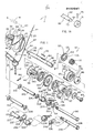
- the rope 12 is wound on a rotatable rope drum 40 which runs on a fixed shaft 41 with a central axis AA.
- the shaft 41 is mounted on opposite walls 22, 24 of a housing 20.
- the cable drum 40 is biased in the winding direction of the cable. As a result, the rope 12 always remains taut and loose rope sections are avoided.
- the pretensioning of the cable drum 40 in one direction of rotation is known per se; it can be generated, for example, with a wound torsion spring 45, one end of which is attached to the cable drum 40 and the other end of which is fixed to the fixed shaft 41.
- the cable drum 40 also has a speed-dependent device, for example pawls 47 or the like, which are actuated by centrifugal force or cams.
- the pawls 47 are articulated on a brake plate 49, which in turn is rotatably arranged on the fixed shaft 41 (Fig. 5,6).
- the pawls 47 are biased with springs 53 so that the end of the respective pawl 47 facing away from the spring makes no contact with Has cam 50 of a cam plate 51.
- the end of a pawl 47 connected to the associated spring 53 extends along and outside the circumference of the cam plate 51 and is guided on straight circumferential sections 51a (FIG. 5).
- the brake plate 49 can rotate relative to the fixed shaft 41 when a force is applied to it. Normally, however, the brake plate 49 does not rotate until the pawls 47 engage the cam plate 51 and a force is thereby exerted on the brake plate 49.
- the cam plate 51 is firmly connected with screws 52 to an end face of the cable drum 40. Therefore, the cam plate 51 rotates together with the cable drum 40.
- each pawl 41 connected to the spring 43 is abruptly acted upon by the peripheral sections 51a of the cam plate 51 and is pushed outwards, the pivoting path of the pawls 47 depending on the rotational speed of the cable drum 40. If a pawl 47 is deflected sufficiently far, it engages behind the shoulder of a cam 50 on the cam plate 51, so that the pawl 47 and the brake plate 49 connected to it rotate at the same rotational speed as the cable drum 40.
- Thin friction disks 56 are arranged between each two clutch disks 55, which are fixed in a rotationally fixed manner on the shaft 41 and are therefore also arranged in a rotationally fixed manner relative to the housing 20. Therefore, the rotation of the brake plate 49 and the clutch disks 55 entrained by it via the projections 54 is caused by friction between the clutch disks 55 and the friction disk ben 56 braked. Accordingly, the rotation of the cable drum 40 is quickly braked and stopped.
- the magnitude of the frictional force between the clutch disks 55 and the friction disks 56 can be adjusted by a device 57 with which the pressure between the clutch disks 55 and the friction disks 56 can be changed by adjusting a nut 57a which can be screwed onto a threaded end of the fixed shaft 41.
- the cable drum 40 When the clutch-brake mechanism is activated when a predetermined rotational speed of the cable drum 40 is reached, the cable drum 40 is gradually decelerated to a rotational speed 0 in a short time. The cable drum 40 is then in a blocked position, ie it is held in a rotationally fixed manner by the interaction of the pawls 47 with the shoulders of the cams 50. The rope 12 can now no longer be pulled out until the rope end is relieved of the load or person attached to it so far that the pretension of the torsion spring 45 becomes effective again. After relieving the rope end, the pawls 47 are pivoted back by their springs 53 into the rest position shown in FIG. 5, and the rope drum 40 can be rotated again - in the unwinding direction of the rope up to the predetermined rotational speed at which the clutch-brake mechanism is actuated again.
- the device 10 shown also includes a device 60 shown in FIGS. 1 and 2 for catching up the person or load.
- This device 60 includes a shaft 62 with an axis BB, which is parallel to the axis AA of the cable drum 40 is arranged.
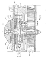
- the shaft 62 is rotatably mounted on the one hand in a bushing 66 of the housing 20 and on the other hand in a bearing 88 of a bearing housing 90 (FIG. 2).
- a pinion 100 is arranged on the shaft 62 in a rotationally fixed but axially displaceable manner.
- the pinion 100 can be brought into engagement with a gear 48 on an end face of the cable drum 40. Normally, the pinion 100 is not in engagement with the gear 48, as is indicated by dash-dotted lines in FIG. 2.
- a pawl 228 is pivoted radially, so that a spring 110 can bring the pinion 100 into engagement with the gear 48 of the cable drum 40, as is shown in FIG. 2 with solid lines.
- a bushing 130 with a T-shaped cross section is fastened on the shaft 62 with a pin 144 and carries a ratchet wheel 152 with friction disks 150, 164 arranged on both sides thereof.
- the ratchet wheel 152 and the friction disks 150, 164 are rotatable and axially displaceable.
- the upper end, of the bush 130 has a thread onto which a nut 170 is screwed, with which the pressure force on the friction disk 164 can be adjusted.
- a handle 182 or the like can be attached to the nut 170 in order to facilitate the turning of the nut 170 in one or the other direction, the handle 182 also simultaneously serving as an abutment to prevent the turning of the nut 170 in certain operating states as described below.
- the ratchet wheel 150 is connected to the socket 130 in a rotationally fixed manner.
- the rotational movement is also transmitted to the ratchet wheel 152.
- the ratchet wheel 152 is assigned two pawls 194 and 220, each of which only allows one direction of rotation of the ratchet wheel 152 (FIGS. 3, 4, the pawl 194 not being shown in FIG. 4).
- the gear 48, the pinion 100 and the cable drum 40 rotate back only a little and only until one of the pawls 194 or 220 engages between the teeth of the ratchet wheel 152. After such an intervention, the clutch is blocked by frictional forces and prevents further lowering of the load or Person at the end of the rope.
- the shaft 62 When the torque required to rotate the shaft 62 counterclockwise becomes less than the torque transmitted from the rope load via the cable drum 40, the gear 48 and the pinion 100 to the shaft 62, the shaft 62 begins to rotate.
- the bushing 130 also rotates with the shaft 62 because it is connected to the shaft 62 in a rotationally fixed manner.
- the rotation of the shaft 62 and the bush 130 causes the nut 170 to tighten on the threaded portion 138, thereby increasing the frictional pressure between the bush 130 and the ratchet wheel 152.
- the increase in friction leads to an increase in the torque which is required for the rotation of the shaft 62, and counteracts this rotation and possibly stops the rotation of the shaft 62 and the cable drum 40.
- controlled downward movements of the cable 12 can be achieved by slow release the mother 170 by allowing a relative movement between the Bush 130 and the ratchet wheel 152 is made possible. This results in rotation of the cable drum 40 and unwinding of the cable 12.
- rotation of the cable drum 40 also leads to a gradual tightening of the nut 170. This in turn slows down or stops the downward movement of the cable 12 until the nut 170 is loosened again somewhat by turning the handle 182.
- a load hanging on the rope can be released in various ways after a fall and after the rope drum 40 has been blocked.
- the cable drum 40 can be rotated by relieving the cable 12 and by subsequent rotation in the unwinding direction at a relatively low rotational speed such that there is little or no relative movement between the nut 170 and the shaft 62.
- the cable drum 40 is released by releasing the cable 12 and turning it back (clockwise in FIG. 1), the handle 182 and the nut 170 being rotated relatively quickly counterclockwise (FIG. 1), unlike in the first case, so that the nut 170 initially rotates faster than the shaft 62.
- this rapid initial movement of the nut 170 relative to the shaft 62 causes an imbalance in the coupling, which results in the cable drum 40 being free to rotate in accordance with the rope load.
- this rotation of the cable drum 40 leads to the shaft 62 also starting to rotate and soon rotating faster than the nut 170, so that the clutch engages again and decelerates the rotation of the cable drum 40 and the shaft 62.
- the rope 12 is handled discontinuously, with acceleration periods and deceleration periods alternating until a complete stop.
- the clutch-brake mechanism of the rope drum 40 responds and decelerates the rotation of the rope drum 40. After activation of the clutch-brake mechanism of the Rope drum 40 is then blocked, and it is necessary to subsequently release the rope drum 40 in order to be able to continue unwinding in one way or another.
- the drive and the nut 170 are initially not turned back in order to pull in the cable 12 and to release the cable drum 40. Rather, the drive and the nut 170 are first rotated in the unwinding direction of the rope 12. During this initial rotation, the shaft 62 is held firmly on the blocked cable drum 40 via the gear 48 and the pinion 100, and by rotating the nut 170 it is axially displaced until it hits a stop, such as a washer 87 in FIG. meets. With further rotation in the same direction of drive and nut 170, shaft 62 is then also rotated.
- the rotating force must be sufficiently large to the resistance of the clutch-brake - mechanism to overcome the cable drum 40th If the torque is large enough, the cable drum 40 is also rotated in a direction in which the rope 12 is unwound. However, as soon as the torque decreases, the rotation of the cable drum 40 is stopped again by the clutch-brake mechanism.
- the housing 20 has a substantially teardrop shape with a connecting device 25 at one end and a section 26 for receiving the cable 12 at the other end.
- the housing 20 consists of two separate halves 27, 28 (FIG. 11), each with flat lateral walls 22, 24 and edges 29, 30 extending therefrom (FIG. 2.11).
- the two halves 27, 28 are connected to one another by screws, rivets or the like, the edges 29, 30 abutting one another.
- the shaft 41 of the cable drum 40 is firmly supported on the opposite walls 22, 24 and the cable drum 40 is rotatably arranged thereon (FIGS. 1, 5, 6).
- the cable drum 40 has a section 42 with a relatively large radius for receiving a torsion spring 45, a section 44 with a smaller radius for receiving the cable 12 and next to it a radial flange 46 which is approximately the same radius as section 44 has.
- the gear 48 is fastened, which has a plurality of teeth 49a arranged on the circumference.
- the diameter of the radial flange 46 is slightly larger than the diameter of the gear 48 .mu.m ensure engagement between gear 48 and pinion 100.
- the shaft 62 with its axis BB is guided at one end 63 in the bush 66, which is arranged in the wall 24 at a location which allows the bush 66 to extend through an opening 67 in the wall 24 (FIG. 2 ).
- the bushing 66 can be held in a non-rotatable manner in a nut 68, which in turn is fastened to the wall 24.
- the rotatable shaft 62 is held in the bush 66 with a guide section 70 adjoining its end 63 and is secured against axial displacement in a groove 74 by means of a snap ring 72.
- a shoulder 76 of the shaft 62 is supported on the upper edge of the bush 66, while a section 80 with a smaller diameter is guided or supported in the bush 66.
- a wedge 82 is fixedly arranged in a longitudinal groove 84 of the shaft 82.
- a bore 86 for receiving a pin is located between the groove 84 and the end 64 of the shaft 62.
- a threaded bore 81 is provided at the end 64, into which a retaining screw 83 is screwed, which carries two washers 85, 87, which serve as a stop for the axial movement of the nut 170 and enable the device to be operated in the third case described above.
- a retaining ring 71 sits on a section 73 with a reduced diameter of the shaft 62 and is fixed with a pin 75.
- the smaller diameter section 73 extends beyond the end of the sleeve 130.
- the annular bearing 88 is fixed to the shaft 62 by a press fit or other known manner, at a location between the longitudinal groove 84 and the bore 86.
- the bearing housing 90 has a radially extending portion 92 with a central bore 93 and one Section 94 extending in the axial direction with a recess 95.
- the bearing housing 90 is fastened by welding or in some other way to the wall 22 of the housing 20 via a circular opening 97 in the wall 22.
- the opening 97 has a slightly larger diameter than the pinion 100.
- a play of e.g. 15 mm is provided between the axially inner end face 98 of the section 92 and the outer surface of the wall 22 in order to have sufficient space for the pinion 100 (FIG. 2).
- the pinion 100 has a disk 102 with teeth 103 arranged on the circumference thereof, which can come into engagement with the teeth 49a of the gear 48.
- the pinion 100 also has an axial flange 104 which is integrally formed on the disk 102 and which has an axial groove 106 on the inside.
- the wedge 82 engages in the axial groove 106, so that the pinion 100 can be displaced in the axial direction along the shaft 62 and is non-rotatably coupled to the latter.
- a coil spring 110 is arranged, which is so long and has such a spring constant that it presses the pinion 100 against the radial flange 46 of the cable drum 40 (FIG. 2).
- the Radial distance between the axis AA of the cable drum 40 and the axis BB of the shaft 62 is such that the pinion 100 is in engagement with the gear 48 on the cable drum 40 when it is in a corresponding position, which in Fig. 2 with solid lines is shown, has been brought.
- the coil spring 110 can also be compressed to such an extent that the inner end face of the disk 102 of the pinion 100 lies axially outside of the pawl 228, which is arranged such that it can cover the opening 97, as in FIG. 2 with dash-dotted lines is shown.
- the inside end face of the disk 102 should bear against the outside end face of the radial flange 46 when the pinion 100 is in engagement with the gear 48.
- the pinion 100 can have an abutment disk 105 (FIG. 2), which is attached to the outer end face of the disk 102 and bears against the outside of the gearwheel 48 when it engages with the pinion 100.
- the gear 48 has a larger diameter than the radial flange 46 and the pinion 100 is held axially by a stop, such as a collar 120, which is shown in FIG. 2 with dashed lines.
- the bush 130 has a substantially T-shaped cross section, which is formed by the radial flange 132 and an axial flange 134 adjoining it.
- the bushing 130 has a through bore 135 in which the shaft 62 is guided or supported.
- the axial flange 134 has a section 136 with a smooth surface and then a threaded section 138.
- a section 140 with a small diameter is located between the two.
- a radial bore 142 is provided for receiving a pin.
- This radial bore 182 is aligned with the bore 86 of the shaft 62, so that the bush 130 can be fastened to the shaft 62 with a pin 144 inserted into the bores 86 and 142.
- the friction disc 150 may be made of conventional synthetic brake material, rubber, or other material with great shock absorbing properties.
- the friction disc 150 is rotatable and axially displaceable on the axial flange 134 of the bush 130 next to the radial flange 132.
- the ratchet wheel 152 has a plurality of teeth 154 extending in the radial direction, which cooperate with the pawls 194 and 220.
- the ratchet wheel 152 has a central bore 156 with a slightly larger diameter than the diameter of the axial flange 134, so that it can rotate freely on the axial flange 134 and move axially.
- An inner end face of the ratchet wheel 152 is arranged directly next to and in contact with the friction disk 150.
- the outer friction disk 164 which can be constructed in the same way as the friction disk 150, is arranged next to and in contact with the other end face 158 of the ratchet wheel 152. According to a preferred embodiment, the friction disk 164 should have a greater shock-absorbing effect with regard to its thickness and compressibility.
- the nut 170 has a central bore 172 with an internal thread 174, which on the thread ab section 138 is turned open, the outer end face of the friction disk 164 being in contact with the associated end face of the nut 170.
- the handle 182 is attached to the nut 170 at one end 184 and carries a handle 187 at the other end 186.
- the handle 187 may also be secured to the housing 20 at the end 186 until the hauling device is put into use.
- the end 186 forms a section 452 on which a pin 454 is rotatably mounted essentially at right angles to it.
- the pin 454 is freely rotatable about its longitudinal axis.
- a knob 458 is fastened to the pin 454 with a pin 460.
- a socket 462 is fastened, in which a further socket 464 is arranged so as to be telescopically displaceable.
- a threaded bolt 468 is arranged in the inner bush 464 in a rotationally fixed and axially displaceable manner.
- the threaded bolt 468 is screwed into the threaded bore 456 by turning the knob 458.
- a spring 466 which surrounds the threaded bolt 468 and is arranged in the inner bush 464 presses the threaded bolt 468 and the bush 464 connected to it outwards into the position shown in FIG. 14.
- the bushing 464 and the threaded bolt 468 can be brought into a position, for example with the aid of a screwdriver or the like, in which the threaded bolt 468 can engage in the threaded bore 456, so that the threaded bolt 468 can be screwed into the threaded bore 456 by turning the knob 458 .
- the button 458 becomes opposite device rotated until the threaded bolt 468 comes out of the threaded bore 456 and is pressed under the action of the spring 466 into the position shown in FIG. 14.
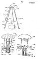
- a lead or plastic seal 470 is located at the lower end of the assembly. An operator can thus recognize whether the arrangement has been moved from the position shown in FIG. 13 to the position shown in FIG. 14.
- the nut 170 has a profiled peripheral surface as an attachment for a ratchet 171, the handle 173 of which replaces the handle 182.
- the nut 170 can be moved in one direction or the other by relatively short pivoting movements of the ratchet 171.
- the reversible ratchet 171, 173 can be attached directly to the nut 170. It is also possible to drive the nut 170 with a reversible motor, e.g. if Loads are to be handled with the device.
- the pawl 194 has a bore 196 at one end and a notch 198 at the other end. It is rotatably mounted on a bush 202, which in turn is arranged on a pawl pin 190.
- the pawl bolt extends through the bore 196 of the pawl 194, through a pawl spring 200, through the bush 202, through a further bush 210 and through washers 212, 214.
- the pawl 194 is arranged next to a shoulder 205 of the sleeve 202 and against the ratchet wheel 152 by the torsion spring 200 biased, which is arranged on a portion 204 of the sleeve 202.
- the torsion spring 200 is supported in the axial direction on a collar 206 of the sleeve 202. Another section 208 of the bush 202 lies against the outside of the wall 22 of the housing 20.
- the bushing 210 is arranged in the region of openings 216, only one of which is shown in FIG. 1, between the walls 22, 24 of the housing 20 in order to withstand the loads which arise when a nut 192 is screwed onto the threaded end of the pawl bolt 190, to record.
- Washers 212, 214 are arranged in the region of both ends of the bush 210. Accordingly, the pawl 194 can pivot about the pawl pin 190 and is biased toward the ratchet wheel 182.
- the other pawl 220 is mounted on an associated pawl pin 222 together with a pawl spring 224, a spacer sleeve 226, the pawl 228 and a bush 230, a section 231 of a bush 227 being rotatably arranged in the bush 230.
- the sleeve 227 in turn serves to receive the pawl pin 222 and is otherwise designed such that the spacer sleeve 226 is rotatably arranged between the pawls 228 and 220 thereon.
- a radial collar 229 of the sleeve 227 serves on the one hand as an abutment for the wall 22 of the housing 20 and on the other hand as an abutment for the pawl 228.
- the upper end of the section 231 abuts the head of the pawl pin 222 and is relative to the surface by frictional forces Jack bolt 222 held.
- pawls 194 and 220 are spaced apart around the circumference of ratchet wheel 152 so that when one pawl engages ratchet wheel 152, the other pawl is disengaged.
- the pawls are arranged so that they come into engagement with the ratchet wheel 152 symmetrically and in phase opposition.
- the short rotational movement of the ratchet wheel 182 is generated by the handle 182 when it is rotated so that the nut 170 is displaced axially inward so far that frictional forces between the bushing 130 and the ratchet wheel 152 act, as described in detail above has been.
- the pinion 100 after being brought into engagement with the gear 48, in this position remains until it is reset by authorized personnel.
- the reset can, as indicated in FIG. 8, be carried out by inserting a special tool, such as an elongated fork 250, preferably with two fork tines 252, 254, into associated holes 256, 258 in the wall 24 directly opposite the pinion 100.
- a special tool such as an elongated fork 250, preferably with two fork tines 252, 254 into associated holes 256, 258 in the wall 24 directly opposite the pinion 100.
- the holes 256, 258 can be provided with a thread so that bolts or the like, not shown, can be screwed in.
- the bolts can be countersunk and covered with paint so that the holes 256, 258 are not immediately discovered by unauthorized persons.
- FIGS. 9 to 12 An advantageous and expedient anchorage for the device for securing against falling and for collecting fallen people or loads is a tripod 270 shown in FIGS. 9 to 12.
- the tripod has a triangular plate 272 which extends essentially horizontally and has bent corners 274.275. Only two bent corners 274, 275 are visible in FIG. 9.
- the plate has a central circular opening 278 through which the cable 12 is passed when the housing 20 of the device is attached to one of the legs of the tripod, as will be described later.
- the opening 278 is surrounded by an upstanding collar 280 which has two bores 281, only one of which is visible in FIG. 9.
- the bores 281 serve to receive an anchor bolt 282.
- the anchor bolt 282 has a bore 283 for a pin at one end and is connected at its other end to a securing line 284 which is fastened to the plate 272 or at another suitable location.
- a securing pin 286 is also attached to a securing line 288 which is attached to the plate 272 or other suitable location so that the securing pin 286 is not lost.
- the locking pin 286 is inserted into the bore 283 after the anchor bolt 282 has been inserted into the openings 281.
- an upright roller housing 290 is fastened, so that the cable 12 can be guided via a deflecting roller 300 mounted thereon through the opening 278 of the plate 272 without coming into contact with the edges of the plate 272.
- the roller housing 290 has two side walls 292, 294, each of which is connected to one another have aligned bores 296 for receiving a roller journal 298, on which the deflection roller 300 runs within the roller housing 290.
- a cover 302 for the deflection rollers 300 has at one end 304 a bore 305 which is aligned with bores 307, only one of which is shown, which are arranged in projections 308 of the roller housing 290.
- a pin 306 is inserted into the bores 305, 307 so that the cover 302 can be swung open.
- the cover 302 can also have a bore 311 at the other end 310, which is aligned with associated bores 316 in projections 314 of the roller housing 290 and into which a pin 312 can be inserted. Accordingly, the rope 12 can be placed around the deflection roller 300 when the cover 312 is swung open, and the rope 12 is also secured on the deflection roller 300 after the cover 302 is closed again and by inserting the pin 312 into the associated bores 311 and 316 is secured.
- two stabilizing plates 320, 322 are attached by welding or the like, in a concentric arrangement to the opening 278 of plate 272.
- the stabilizing plates 320, 322 hold the housing 20 of the device in a relatively fixed position when it is fastened to the tripod by means of the anchor bolt 282 becomes as shown in Fig. 11.
- the construction and construction of the tripod 270 and the locking plates 320, 322 are such that the contours of the locking plates 320, 322 are adapted to the dimensions of the housing 20 accommodated therein.
- a support leg 326, 328 is attached to each of the three corners of the tripod 270 by welding or the like.
- Each of these support legs has three sides 330, 331 and 332.
- the inward side 333 is open (Fig. 9).
- the supporting legs 326, 328 have a square cross section and take up standing legs with a square cross section.
- Each of the outer sides 331 has an upper cutout 335, which at the same time delimits an upper side part 331A and facilitates the up and down movement of the upper part of the associated supporting leg.
- the tripod 270 has three legs 340,342,344, each of which has an upper section 346, which preferably consists of a high-strength, square hollow profile, and a lower section 348, which preferably consists of a high-strength hollow section with a square cross-section and is disposed within the upper portion 346.
- the upper and lower sections 346, 348 each have a plurality of aligned holes 350, 352 which are arranged so that they can be brought into register with one another and that retaining pins 353 can be inserted into aligned holes. The length of the legs of the tripod 270 can thus be adjusted.
- a pivotable foot 354 in a conventional ladder construction has slot holes 355 which are aligned with the lowermost holes 356 of each leg 340, 342, 344, so that a leg 354 can be connected to each leg using a pin 357.
- the tripod 270 has three legs of adjustable length, each leg having a pivoting foot.
- the upper end of the respective upper sections 346 is pivotable about a bolt 360 on the support leg 326 or 328 (FIG. 9), the bolt 360 extending through mutually opposite bores 362 in the support legs 326, 328 and through downward slits 364 of the respective upper sections 346 of the legs.
- each upper section 346 is not only pivotally mounted about the bolt 360, but is also relatively displaceable relative to the bolt 360 by the length of the slot 364. If an upper section 346 is displaced upward relative to the bolt, it can no longer move around the bolt be pivoted because it abuts the side portion 331A. However, when the upper portion 346 is pivoted downward relative to the bolt 360, it can be pivoted inward, with its upper end pivoting out through the cutout 335 of the side 331. So that a leg is not inadvertently pulled down and swivels inward, each leg or each upper section 346 is prestressed with a spring 370.
- One end of the spring 370 is fixed to the pin 360 and the other end to a pin 366 at the lower portion 348. Accordingly, the legs of the tripod 217 can be pivoted between an inner position and an outer position.
- the pivoting path into the outer position is limited in that the support legs 326, 328 form an abutment and that each leg, when pivoted into the outer position, is blocked by the pretension. Before a leg can be swiveled inwards, it must first be pulled down, the force to be applied depends on the size of the preload.
- the housing 20 of the device is of a middle one Part of the tripod 270 suspended and attached to it, for example with anchor bolts 282.
- the housing may have a foldable handle 399 in order to facilitate manipulation of the device 10 when the handle 182 is actuated.
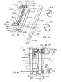
- a bracket 400 is attached to a support leg 340 of the tripod 270, specifically below the roller housing 290 for the deflecting roller 100.
- the housing 20 is detachably arranged on the bracket 400, in such a way that the outlet opening for the cable 12 on the housing 20 is directed upwards in the direction of the deflecting roller 300 and that the handle 182 or a corresponding drive of the device 60 is directed outwards for catching up, so that a person standing next to the tripod 270 can easily move the Handle 282 can operate.
- the console 400 has two elongated angle profiles 402, 404 with legs 406, 408 directed laterally outwards and legs 410.412 directed inwards.
- a gap 414 between the opposing surfaces of the legs 410, 412 serves to receive the upper section 346 of the supporting leg 340, which is arranged therein with close play.
- the gap 416 extends continuously from the front end 416 to the rear end 418 of the console.
- At the front ends of the two legs 406 and 408 outward holding plates 420, 422 are fastened, for example by welding or the like, which serve to hold the housing 20 of the device.
- Each of the retaining plates 420, 422 has tabs 424, 426 bent back at the free end, which prevent the housing 20 from falling out once it has been was used.
- the two legs 406, 408 are connected to one another in the region of the front end 416 by a web 426 which is welded to the legs 406, 408.
- the two legs 406, 408 are connected to one another by a crossmember 428, which is also welded on.
- Stiffening webs 430, 432 are welded onto the legs 406, 408 and extend in the longitudinal direction of the angle profiles 402, 404 between the upper end 416 and the crossmember 428.
- the stiffening webs 430, 432 support the one wall 24 of the housing 20 of the device.
- the stiffening webs can have outwardly beveled sections 434, 436 at the lower end, which are supported on the crossmember 428.
- the projection 438 carries a pin 440 to which a retaining pin 441 can be attached to prevent displacement of the housing 20 when it is on the Console 400 has been placed.
- the console 400 To connect the console 400 to a supporting leg, there are bores 442 aligned with one another at the rear end of the legs 406, 408, to which holes 350 on the supporting leg 340 are assigned, so that the console can be held on the supporting leg 340 with an inserted pin 444.
- the console 400 In addition, in the area of the upper end there are bores 446 which are aligned with one another and into which a pin 448 can be inserted, which is arranged beneath the supporting leg 340 when the bracket 400 is placed on the supporting leg 340 and thereby fixes the bracket 400 to the supporting leg 340.
- the console 400 can be made entirely of high-strength material and be provided with a resistant coating made of plastic or the like.
- the housing 20 can be securely fastened to the console 400 in such a way that actuation of the device 60 for retraction is possible without problems.
- the console 400 is also attached to a leg 340 of the tripod 270 so that it can be quickly assembled and disassembled.
- the device 10 can also be anchored to an I-beam 500, around which a flexible cushion 502 is placed to avoid wear.
- a rope 504 is placed around the carrier 500 and over the cushion 502, which has snap hooks 506 at its ends, which engage in a ring 508.
- the ring in turn carries a snap hook 510 on which the connection device 25 of the device 10 hangs. 15 also shows "that the handle 399 can be folded against the housing 20 for stabilization when not in use.
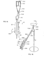
- FIG. 16 shows a portable embodiment of a device 530 that can be head-connected to an anchor 548.
- the device has the console 400, which is constructed identically, as in the embodiment according to FIG. 10.
- the console 400 carries on its underside a plate 532 which is connected by screws, by welding or in another way and has a handle 534 attached to its lower end which is used to manipulate and hold the device 530 during use.
- a longer tube 536 is connected, in which the Rope 12 is guided.
- a roller housing 540 for a deflection roller 542 rotatably arranged therein.
- a snap hook 544 is also fastened to the roller housing 540, with which the device 530 can be connected to a ring 546 of the armature 548. 16 makes it clear that the device 10 or 530 can be used in any position, taking into account its own weight, and is then also operational.
- the tripod 270 of Fig. 9 can also be used together with other devices, e.g. with a 560 winch.
- the winch 560 has a housing 562 which is fastened to a bracket 563 in the lower region of the supporting leg 340.
- a tube 564 adjoins the winch 560, which extends along the support leg 340 and is fixed at the upper end of the support leg 340 with brackets 566 and associated pins.
- the upper end of the tube 564 merges into a roller housing 568 in which a deflection roller (not shown) runs, over which the winch cable 570 is guided, which is then guided through a central opening in the plate 272 of the tripod 270.
- Fig. 18 shows a modified version, in which a portable winch 561 with winch housing 562, subsequent tube 564, roller housing 574 and connecting hook 576 is suspended under the plate 272 of the tripod 270.
- horizontal supports 600, 602 are provided between the legs 342, 344, which are provided with clamps or otherwise secured to the legs 342,344.
- the console 400 is attached to the brackets 600, 602.
- the roller housing 290 is located opposite the upper end of the leg 340.
- FIG. 20 shows an embodiment in which the roller housing 590 is fastened below the plate 272 of the tripod 270, so that the associated deflecting roller 291 is also located below the plate 272.
- webs 598 directed downwards are fastened to the edge of the plate 272 and are also connected to the supporting legs 326, 328.
- the deflection roller 596 is arranged within the recess formed by the webs 598.
- the console 400 can also be attached to the leg 346 in a lateral orientation.
Landscapes
- Engineering & Computer Science (AREA)
- Mechanical Engineering (AREA)
- Health & Medical Sciences (AREA)
- General Health & Medical Sciences (AREA)
- Business, Economics & Management (AREA)
- Emergency Management (AREA)
- Emergency Lowering Means (AREA)
- Spinning Or Twisting Of Yarns (AREA)
Priority Applications (1)
| Application Number | Priority Date | Filing Date | Title |
|---|---|---|---|
| AT85101115T ATE44242T1 (de) | 1984-02-10 | 1985-02-04 | Vorrichtung zur absturzsicherung und zum einholen abgestuerzter personen oder lasten. |
Applications Claiming Priority (2)
| Application Number | Priority Date | Filing Date | Title |
|---|---|---|---|
| US578963 | 1984-02-10 | ||
| US06/578,963 US4589523A (en) | 1984-02-10 | 1984-02-10 | Fall arrester and emergency retrieval apparatus and anchor apparatus therefor |
Publications (3)
| Publication Number | Publication Date |
|---|---|
| EP0152041A2 true EP0152041A2 (fr) | 1985-08-21 |
| EP0152041A3 EP0152041A3 (en) | 1986-10-22 |
| EP0152041B1 EP0152041B1 (fr) | 1989-06-28 |
Family
ID=24315043
Family Applications (1)
| Application Number | Title | Priority Date | Filing Date |
|---|---|---|---|
| EP85101115A Expired EP0152041B1 (fr) | 1984-02-10 | 1985-02-04 | Dispositif pour prévenir les chutes et pour lever des personnes ou charges ayant fait une chute |
Country Status (4)
| Country | Link |
|---|---|
| US (1) | US4589523A (fr) |
| EP (1) | EP0152041B1 (fr) |
| AT (1) | ATE44242T1 (fr) |
| DE (1) | DE3571206D1 (fr) |
Cited By (6)
| Publication number | Priority date | Publication date | Assignee | Title |
|---|---|---|---|---|
| WO1991011217A1 (fr) * | 1990-01-27 | 1991-08-08 | Denis Ferranti Meters Limited | Dispositif de securite |
| WO1992007626A1 (fr) * | 1990-10-31 | 1992-05-14 | Barrow Hepburn Sala Ltd | Dispositif d'arret de chute |
| EP0539759A1 (fr) * | 1991-10-03 | 1993-05-05 | Rose Systems, Inc. | Appareil pour limiter la charge dans un engine de levage |
| WO1997042121A1 (fr) * | 1996-05-07 | 1997-11-13 | Josef Martin Metallverarbeitung Ges.Mbh & Co. Kg | Installation de levage |
| WO2008134698A1 (fr) * | 2007-04-30 | 2008-11-06 | Ferno-Washington, Inc. | Directionnel eleve presentant un nombre configurable de pieds telescopiques |
| EP4349763A1 (fr) * | 2022-10-05 | 2024-04-10 | Safehold Limited | Trépied |
Families Citing this family (57)
| Publication number | Priority date | Publication date | Assignee | Title |
|---|---|---|---|---|
| US4660679A (en) * | 1986-02-10 | 1987-04-28 | Meyer Ostrobrod | Safety alarm tripod |
| US4877110A (en) * | 1988-10-14 | 1989-10-31 | D B Industries, Inc. | Safety device with retractable lifeline |
| US5022489A (en) * | 1990-06-15 | 1991-06-11 | Sauber Mfg. Co. | Hoisting apparatus for a manhole |
| US5090507A (en) * | 1990-10-29 | 1992-02-25 | Rose Manufacturing Company | Load limiting apparatus for a hoist |
| US5150768A (en) * | 1990-10-29 | 1992-09-29 | Rose Manufacturing Company | Load limiting apparatus for a hoist |
| WO1994008658A1 (fr) * | 1992-10-14 | 1994-04-28 | Rose Systems, Inc. | Appareil de securite |
| US5431248A (en) * | 1993-10-25 | 1995-07-11 | Willaughby; Donald | Confined space lowering and retrieving apparatus |
| EP0739225B1 (fr) * | 1994-01-13 | 1997-12-29 | Barrow Hepburn Sala Limited | Dispositif de couplage reagissant a la vitesse, con u en particulier pour des dispositifs antichute |
| US5498011A (en) * | 1994-02-02 | 1996-03-12 | American Safety Products, Inc. | Lifeline retrieval device |
| US5603488A (en) * | 1994-10-21 | 1997-02-18 | Surety Manufacturing & Testing Ltd. | Rail attachable rescue frame for rail bridges |
| US5725070A (en) * | 1995-02-13 | 1998-03-10 | Eldred; Harold J. | Trailer-based support frame for use in vertically transferring persons and equipment |
| US5820108A (en) * | 1995-08-21 | 1998-10-13 | Ostrobrod; Meyer | Monopod anchoring device |
| US5899298A (en) * | 1997-03-19 | 1999-05-04 | Crouse, Jr.; Benjamin F. | Safety harness for stairs |
| FR2804332B1 (fr) * | 2000-01-31 | 2002-04-19 | Applic Mecanique Electr Et Fri | Dispositif d'acces securise a l'interieur d'une structure, notamment d'un reservoir muni d'une ouverture |
| US20030057018A1 (en) * | 2001-09-27 | 2003-03-27 | Dodson William D. | Retractable safety tether and harness assembly |
| US6899238B2 (en) * | 2001-10-05 | 2005-05-31 | D B Industries, Inc. | Methods and apparatus for supporting a davit arm |
| US20070036640A1 (en) * | 2003-03-12 | 2007-02-15 | Randy Boudreaux | Methods, systems and apparatuses for retrieving an entity from a confined space |
| US7281620B2 (en) * | 2003-09-05 | 2007-10-16 | D B Industries, Inc. | Self-retracting lifeline |
| US20050161285A1 (en) * | 2004-01-27 | 2005-07-28 | Blackford Matthew J. | Ratcheting anchorage device |
| US7699292B2 (en) * | 2004-03-30 | 2010-04-20 | James Earl Barnett | Flange mounted load transition apparatus and method |
| US7469771B2 (en) * | 2004-10-29 | 2008-12-30 | Techxotic Lc | High directional and kit for a high directional |
| US20070227995A1 (en) * | 2006-03-31 | 2007-10-04 | D B Industries, Inc. | Davit assembly |
| GB2440134B (en) * | 2006-07-14 | 2011-04-20 | Latchways Plc | Speed responsive engagement device |
| US8192126B1 (en) * | 2007-02-07 | 2012-06-05 | Telpro, Inc. | Mobile hoist system |
| US20080237415A1 (en) * | 2007-03-28 | 2008-10-02 | John Michalec | Hoist apparatus |
| WO2008137723A2 (fr) * | 2007-05-02 | 2008-11-13 | T.A. Pelsue Company | Système de récupération et d'arrêt de chute pour des applications de trou d'homme |
| US7780146B2 (en) * | 2007-09-28 | 2010-08-24 | D B Industries, Inc. | Retrieval assembly |
| IL190512A0 (en) * | 2008-03-30 | 2008-12-29 | Alon Tavori | Portable apparatus for rescue from elevated locations |
| US8701833B2 (en) * | 2008-04-22 | 2014-04-22 | Gf Protection Inc. | Distance limiting self-retractable lifeline |
| GB2467953B (en) * | 2009-02-20 | 2013-07-17 | Latchways Plc | Fall arrest system safety device |
| US10688323B2 (en) * | 2009-03-09 | 2020-06-23 | D B Industries, Llc | Safety device with fall arrest and descending modes |
| US9764172B2 (en) * | 2009-03-09 | 2017-09-19 | D B Industries, Llc | Safety device with fall arrest and descending modes |
| US8567562B2 (en) * | 2009-11-02 | 2013-10-29 | B D Industries, LLC | Brake assembly for a self-retracting lifeline assembly |
| US20110174914A1 (en) * | 2010-01-20 | 2011-07-21 | Gimmal Co., Ltd. | Connector device to prevent person from falling |
| USD656686S1 (en) | 2010-03-17 | 2012-03-27 | LynRus Aluminum Products, LLC | Auto-arresting safety device |
| WO2012068420A2 (fr) * | 2010-11-17 | 2012-05-24 | Reliance Industries, Llc | Dispositif antichute rétractable doté d'un assemblage de composant et d'un arbre principal en porte-à-faux |
| CA2860425C (fr) * | 2011-01-28 | 2015-08-18 | Tuffbuilt Products Inc. | Dispositif d'absorption des charges de choc |
| US9056753B2 (en) | 2011-10-18 | 2015-06-16 | LynRus Aluminum Products, LLC | Disabling system for auto-arresting safety device |
| US9121462B2 (en) | 2011-10-28 | 2015-09-01 | D B Industries, Llc | Self-retracting lifeline |
| CN102923565A (zh) * | 2012-11-06 | 2013-02-13 | 南通建筑工程总承包有限公司 | 一种简易倒链提升支架 |
| US10004927B2 (en) | 2012-12-02 | 2018-06-26 | Reliance Industries, Llc | Retractable lanyard lock mechanism |
| US9821178B2 (en) | 2013-02-08 | 2017-11-21 | D B Industries, Llc | Bracket assembly |
| CN104030203A (zh) | 2013-03-08 | 2014-09-10 | 煤矿安全设备公司 | 支架和升/降设备总成 |
| US8752671B1 (en) * | 2013-04-11 | 2014-06-17 | Diane Henderson Holman | Portable collapsible horse-mounting device |
| US20150307197A1 (en) * | 2014-04-28 | 2015-10-29 | Capewell Systems Llc | Multi-Use Emergency Descent Device |
| WO2016038417A1 (fr) * | 2014-09-08 | 2016-03-17 | Palomo Adírcio José | Améliorations apportées à un dispositif antichutes rétractable |
| US10792520B2 (en) * | 2014-09-12 | 2020-10-06 | D B Industries, Llc | Personal descent system |
| GB2539418B (en) * | 2015-06-15 | 2019-10-02 | Swisslogo Ag | Self-braking pulley |
| EP3210650B1 (fr) | 2016-02-28 | 2018-07-04 | Honeywell International Inc. | Guidage de câble |
| FR3053598B1 (fr) * | 2016-07-11 | 2018-08-10 | Total Raffinage Chimie | Dispositif d'acces securise a un espace confine, notamment un espace confine a acces lateral. |
| US20180236274A1 (en) * | 2017-02-22 | 2018-08-23 | Jeffrey D. Decker | Retrieval tower and rescue method for sloped roof structures |
| CN106969745B (zh) * | 2017-03-20 | 2019-06-28 | 浙江荣庆工程管理有限公司 | 一种水准仪及其上的三脚架 |
| DE102019120036A1 (de) * | 2019-07-24 | 2021-01-28 | Columbus Mckinnon Industrial Products Gmbh | Hebezeug |
| CN112791324B (zh) * | 2021-01-27 | 2022-05-13 | 重庆市巴岳建筑安装工程有限公司 | 一种高空作业安全防护装置 |
| US20220348442A1 (en) * | 2021-05-01 | 2022-11-03 | Alexander Andrew, Inc. Dba Falltech | Confined space tripod pulley improvements |
| CN113679980A (zh) * | 2021-09-02 | 2021-11-23 | 四川水利职业技术学院 | 一种高空速差防坠器及高空作业设备 |
| US12565406B2 (en) * | 2024-03-21 | 2026-03-03 | Hangzhou Rock Machinery Manufacture Co., Ltd | Hand winch |
Family Cites Families (10)
| Publication number | Priority date | Publication date | Assignee | Title |
|---|---|---|---|---|
| US1950289A (en) * | 1933-03-22 | 1934-03-06 | Equipment Company Inc Const | Scaffold hoist |
| US1950288A (en) * | 1933-03-22 | 1934-03-06 | Equipment Company Inc Const | Scaffold hoist |
| DE894354C (de) * | 1938-04-02 | 1953-10-22 | Joseph Trouin | Vorrichtung zum Schutz gegen Abstuerzen |
| US2518934A (en) * | 1946-08-14 | 1950-08-15 | Hayden H Renner | Safety device |
| US2802637A (en) * | 1955-04-29 | 1957-08-13 | Robert C Gschwind | Automatic cable rewind for a safety device |
| AT217871B (de) * | 1957-09-16 | 1961-10-25 | Kurt Erich Wittner | Vorrichtung zum Absteigen und Aufsteigen mit Hilfe eines an einem festen Punkt aufgehängten Seiles |
| US3760910A (en) * | 1972-04-14 | 1973-09-25 | A Koshihara | Safety device |
| US3915432A (en) * | 1973-11-13 | 1975-10-28 | Carlos Roberto Bustamante | Triple action mechanical chute-hoist |
| DD124637A1 (fr) * | 1976-03-18 | 1977-03-09 | ||
| DE2915607C2 (de) * | 1979-04-18 | 1984-10-31 | Brda, Walter, 8112 Bad Kohlgrub | Sicherungs- und Rettungsgestell |
-
1984
- 1984-02-10 US US06/578,963 patent/US4589523A/en not_active Expired - Lifetime
-
1985
- 1985-02-04 AT AT85101115T patent/ATE44242T1/de not_active IP Right Cessation
- 1985-02-04 EP EP85101115A patent/EP0152041B1/fr not_active Expired
- 1985-02-04 DE DE8585101115T patent/DE3571206D1/de not_active Expired
Cited By (7)
| Publication number | Priority date | Publication date | Assignee | Title |
|---|---|---|---|---|
| WO1991011217A1 (fr) * | 1990-01-27 | 1991-08-08 | Denis Ferranti Meters Limited | Dispositif de securite |
| WO1992007626A1 (fr) * | 1990-10-31 | 1992-05-14 | Barrow Hepburn Sala Ltd | Dispositif d'arret de chute |
| AU645364B2 (en) * | 1990-10-31 | 1994-01-13 | Barrow Hepburn Sala Ltd | Fall-arrest apparatus |
| EP0539759A1 (fr) * | 1991-10-03 | 1993-05-05 | Rose Systems, Inc. | Appareil pour limiter la charge dans un engine de levage |
| WO1997042121A1 (fr) * | 1996-05-07 | 1997-11-13 | Josef Martin Metallverarbeitung Ges.Mbh & Co. Kg | Installation de levage |
| WO2008134698A1 (fr) * | 2007-04-30 | 2008-11-06 | Ferno-Washington, Inc. | Directionnel eleve presentant un nombre configurable de pieds telescopiques |
| EP4349763A1 (fr) * | 2022-10-05 | 2024-04-10 | Safehold Limited | Trépied |
Also Published As
| Publication number | Publication date |
|---|---|
| DE3571206D1 (en) | 1989-08-03 |
| US4589523A (en) | 1986-05-20 |
| EP0152041B1 (fr) | 1989-06-28 |
| EP0152041A3 (en) | 1986-10-22 |
| ATE44242T1 (de) | 1989-07-15 |
Similar Documents
| Publication | Publication Date | Title |
|---|---|---|
| EP0152041B1 (fr) | Dispositif pour prévenir les chutes et pour lever des personnes ou charges ayant fait une chute | |
| DE69109855T2 (de) | Sicherheitsverankerung zum reglen der sicherungsseilausgabe. | |
| DE60133201T2 (de) | Gerät zum kontrollierten herablassen | |
| EP3526427B1 (fr) | Dispositif de sécurité anti-chute pour les personnes | |
| EP1279350B1 (fr) | Manche de parasol et parasol comprenant un tel manche | |
| EP0884067B1 (fr) | Dispositif de freinage pour appareil de remontée et descente | |
| EP0653947A1 (fr) | Appareil pour descendre par cable ou pour hisser des personnes et/ou des charges sur des hauteurs elevees. | |
| DE2852871C2 (fr) | ||
| DE69707258T2 (de) | Gerät zum Anbringen von Deckplatten | |
| DE19951064C2 (de) | Kettenflaschenzug | |
| DE3028586A1 (de) | Rettungsgeraet zum abseilen von personen | |
| EP3395746B1 (fr) | Palan à chaîne | |
| DE102012202257B4 (de) | Hebevorrichtung, insbesondere Patientenlifter, mit Abrollsicherung | |
| EP4385598B1 (fr) | Dispositif pour maintenir au moins une personne | |
| EP0610664B1 (fr) | Dispositif de levage et de support dans le domaine des soins | |
| DE102010055681B4 (de) | Vorrichtung zum Haltern eines Gegenstands mit Gewichtsausgleich | |
| EP0859646B1 (fr) | Treuil pour appareil de levage et d'abaissement | |
| DE2617784A1 (de) | Bei unbeabsichtigter rotation anhaltbare welle | |
| EP2890461B1 (fr) | Coulisseau pour système d'assurage avec élément de guidage | |
| DE1815566C (de) | Vorrichtung zum Heben und Senken von transportablen Großbehältern | |
| EP0324127A2 (fr) | Appareil avec tambour à câble pour faire monter ou descendre une personne sous son propre contrôle | |
| AT500779B1 (de) | Sicherheitskurbel zum heben und senken von lasten | |
| AT400927B (de) | Rettungs- und abseilgerät | |
| DE2616769A1 (de) | Einziehvorrichtung fuer sicherheitsgurte | |
| AT393713B (de) | Aufzieh- und wendevorrichtung fuer eine lamellenjalousie |
Legal Events
| Date | Code | Title | Description |
|---|---|---|---|
| PUAI | Public reference made under article 153(3) epc to a published international application that has entered the european phase |
Free format text: ORIGINAL CODE: 0009012 |
|
| AK | Designated contracting states |
Designated state(s): AT BE CH DE FR GB IT LI LU NL SE |
|
| PUAL | Search report despatched |
Free format text: ORIGINAL CODE: 0009013 |
|
| AK | Designated contracting states |
Kind code of ref document: A3 Designated state(s): AT BE CH DE FR GB IT LI LU NL SE |
|
| 17P | Request for examination filed |
Effective date: 19870123 |
|
| 17Q | First examination report despatched |
Effective date: 19880419 |
|
| GRAA | (expected) grant |
Free format text: ORIGINAL CODE: 0009210 |
|
| AK | Designated contracting states |
Kind code of ref document: B1 Designated state(s): AT BE CH DE FR GB IT LI LU NL SE |
|
| REF | Corresponds to: |
Ref document number: 44242 Country of ref document: AT Date of ref document: 19890715 Kind code of ref document: T |
|
| REF | Corresponds to: |
Ref document number: 3571206 Country of ref document: DE Date of ref document: 19890803 |
|
| ET | Fr: translation filed | ||
| GBT | Gb: translation of ep patent filed (gb section 77(6)(a)/1977) | ||
| ITF | It: translation for a ep patent filed | ||
| PLBE | No opposition filed within time limit |
Free format text: ORIGINAL CODE: 0009261 |
|
| STAA | Information on the status of an ep patent application or granted ep patent |
Free format text: STATUS: NO OPPOSITION FILED WITHIN TIME LIMIT |
|
| 26N | No opposition filed | ||
| ITTA | It: last paid annual fee | ||
| EPTA | Lu: last paid annual fee | ||
| EAL | Se: european patent in force in sweden |
Ref document number: 85101115.5 |
|
| PGFP | Annual fee paid to national office [announced via postgrant information from national office to epo] |
Ref country code: SE Payment date: 19960220 Year of fee payment: 12 Ref country code: BE Payment date: 19960220 Year of fee payment: 12 Ref country code: AT Payment date: 19960220 Year of fee payment: 12 |
|
| PGFP | Annual fee paid to national office [announced via postgrant information from national office to epo] |
Ref country code: CH Payment date: 19960227 Year of fee payment: 12 |
|
| PGFP | Annual fee paid to national office [announced via postgrant information from national office to epo] |
Ref country code: NL Payment date: 19960228 Year of fee payment: 12 |
|
| PGFP | Annual fee paid to national office [announced via postgrant information from national office to epo] |
Ref country code: LU Payment date: 19960501 Year of fee payment: 12 |
|
| PG25 | Lapsed in a contracting state [announced via postgrant information from national office to epo] |
Ref country code: LU Free format text: LAPSE BECAUSE OF NON-PAYMENT OF DUE FEES Effective date: 19970204 Ref country code: AT Effective date: 19970204 |
|
| PG25 | Lapsed in a contracting state [announced via postgrant information from national office to epo] |
Ref country code: SE Effective date: 19970205 |
|
| PG25 | Lapsed in a contracting state [announced via postgrant information from national office to epo] |
Ref country code: LI Effective date: 19970228 Ref country code: CH Effective date: 19970228 Ref country code: BE Effective date: 19970228 |
|
| BERE | Be: lapsed |
Owner name: ROSE MFG CY Effective date: 19970228 |
|
| PG25 | Lapsed in a contracting state [announced via postgrant information from national office to epo] |
Ref country code: NL Effective date: 19970901 |
|
| REG | Reference to a national code |
Ref country code: CH Ref legal event code: PL |
|
| EUG | Se: european patent has lapsed |
Ref document number: 85101115.5 |
|
| NLV4 | Nl: lapsed or anulled due to non-payment of the annual fee |
Effective date: 19970901 |
|
| PGFP | Annual fee paid to national office [announced via postgrant information from national office to epo] |
Ref country code: GB Payment date: 19990412 Year of fee payment: 15 |
|
| PGFP | Annual fee paid to national office [announced via postgrant information from national office to epo] |
Ref country code: FR Payment date: 19990420 Year of fee payment: 15 |
|
| PGFP | Annual fee paid to national office [announced via postgrant information from national office to epo] |
Ref country code: DE Payment date: 19990426 Year of fee payment: 15 |
|
| PG25 | Lapsed in a contracting state [announced via postgrant information from national office to epo] |
Ref country code: GB Free format text: LAPSE BECAUSE OF NON-PAYMENT OF DUE FEES Effective date: 20000204 |
|
| GBPC | Gb: european patent ceased through non-payment of renewal fee |
Effective date: 20000204 |
|
| PG25 | Lapsed in a contracting state [announced via postgrant information from national office to epo] |
Ref country code: FR Free format text: LAPSE BECAUSE OF NON-PAYMENT OF DUE FEES Effective date: 20001031 |
|
| PG25 | Lapsed in a contracting state [announced via postgrant information from national office to epo] |
Ref country code: DE Free format text: LAPSE BECAUSE OF NON-PAYMENT OF DUE FEES Effective date: 20001201 |
|
| REG | Reference to a national code |
Ref country code: FR Ref legal event code: ST |