EP0152113A1 - Appareil diagnostic à ultrasons - Google Patents
Appareil diagnostic à ultrasons Download PDFInfo
- Publication number
- EP0152113A1 EP0152113A1 EP85101628A EP85101628A EP0152113A1 EP 0152113 A1 EP0152113 A1 EP 0152113A1 EP 85101628 A EP85101628 A EP 85101628A EP 85101628 A EP85101628 A EP 85101628A EP 0152113 A1 EP0152113 A1 EP 0152113A1
- Authority
- EP
- European Patent Office
- Prior art keywords
- signal
- kernel
- ultrasonic wave
- ultrasonic
- depth
- Prior art date
- Legal status (The legal status is an assumption and is not a legal conclusion. Google has not performed a legal analysis and makes no representation as to the accuracy of the status listed.)
- Granted
Links
- 230000010363 phase shift Effects 0.000 claims abstract description 6
- 238000000034 method Methods 0.000 claims description 13
- 238000012545 processing Methods 0.000 claims description 10
- 230000015654 memory Effects 0.000 claims description 4
- 238000005259 measurement Methods 0.000 description 4
- 230000006866 deterioration Effects 0.000 description 3
- 230000006870 function Effects 0.000 description 3
- 238000010276 construction Methods 0.000 description 2
- 238000010586 diagram Methods 0.000 description 2
- 238000011160 research Methods 0.000 description 2
- 230000005540 biological transmission Effects 0.000 description 1
- 238000012512 characterization method Methods 0.000 description 1
- 238000001514 detection method Methods 0.000 description 1
- 230000010354 integration Effects 0.000 description 1
- 238000012986 modification Methods 0.000 description 1
- 230000004048 modification Effects 0.000 description 1
- 230000008569 process Effects 0.000 description 1
- 238000011002 quantification Methods 0.000 description 1
- 238000001454 recorded image Methods 0.000 description 1
- 238000001028 reflection method Methods 0.000 description 1
- 230000002459 sustained effect Effects 0.000 description 1
- 238000001308 synthesis method Methods 0.000 description 1
Images
Classifications
-
- G—PHYSICS
- G01—MEASURING; TESTING
- G01H—MEASUREMENT OF MECHANICAL VIBRATIONS OR ULTRASONIC, SONIC OR INFRASONIC WAVES
- G01H3/00—Measuring characteristics of vibrations by using a detector in a fluid
-
- G—PHYSICS
- G01—MEASURING; TESTING
- G01H—MEASUREMENT OF MECHANICAL VIBRATIONS OR ULTRASONIC, SONIC OR INFRASONIC WAVES
- G01H5/00—Measuring propagation velocity of ultrasonic, sonic or infrasonic waves, e.g. of pressure waves
-
- G—PHYSICS
- G01—MEASURING; TESTING
- G01S—RADIO DIRECTION-FINDING; RADIO NAVIGATION; DETERMINING DISTANCE OR VELOCITY BY USE OF RADIO WAVES; LOCATING OR PRESENCE-DETECTING BY USE OF THE REFLECTION OR RERADIATION OF RADIO WAVES; ANALOGOUS ARRANGEMENTS USING OTHER WAVES
- G01S15/00—Systems using the reflection or reradiation of acoustic waves, e.g. sonar systems
- G01S15/88—Sonar systems specially adapted for specific applications
- G01S15/89—Sonar systems specially adapted for specific applications for mapping or imaging
- G01S15/8906—Short-range imaging systems; Acoustic microscope systems using pulse-echo techniques
- G01S15/8977—Short-range imaging systems; Acoustic microscope systems using pulse-echo techniques using special techniques for image reconstruction, e.g. FFT, geometrical transformations, spatial deconvolution, time deconvolution
-
- G—PHYSICS
- G01—MEASURING; TESTING
- G01S—RADIO DIRECTION-FINDING; RADIO NAVIGATION; DETERMINING DISTANCE OR VELOCITY BY USE OF RADIO WAVES; LOCATING OR PRESENCE-DETECTING BY USE OF THE REFLECTION OR RERADIATION OF RADIO WAVES; ANALOGOUS ARRANGEMENTS USING OTHER WAVES
- G01S7/00—Details of systems according to groups G01S13/00, G01S15/00, G01S17/00
- G01S7/52—Details of systems according to groups G01S13/00, G01S15/00, G01S17/00 of systems according to group G01S15/00
- G01S7/52017—Details of systems according to groups G01S13/00, G01S15/00, G01S17/00 of systems according to group G01S15/00 particularly adapted to short-range imaging
- G01S7/52023—Details of receivers
- G01S7/52036—Details of receivers using analysis of echo signal for target characterisation
Definitions
- tissue characterization which is aimed at the quantification of tissue characteristics according to the variations of physical quantities which are sustained by an ultrasonic wave when it propagates through tissues of a living body.
- velocity has been chosen as a representative physical quantity of ultrasonic waves, and measurements have been made by means of the prior art measuring method which utilizes the transmitted wave.
- An object of the present invention is to provide an ultrasonic diagnostic equipment which permits to determine the average velocity of the ultrasonic wave by the ultrasonic pulse reflection method.
- Another object of the present invention is to provide an ultrasonic diagnostic equipment which permits to measure the velocity of the ultrasonic wave by utilizing the technique of the synthetic aperture method.
- the ultrasonic diagnostic equipment in accordance with the present invention includes an ultrasonic transducer which driven by a pulser so-as to transmit an ultrasonic wave and receive the reflected ultrasonic wave from an object, a phase detector which obtains hologram signal for the object by detecting the phase shift of the signals received by the ultrasonic transducer, a signal generator which generates reference signals required for synthetic aperture processing that uses the depth of the object as the parameter, and an operational unit which determines the reconstructed data for the object by carrying out synthetic aperture method by the use of the kernel signal and the hologram signal.
- the ultrasonic diagnostic equipment is equipped with a control unit which controls the operational unit and the signal generator so as to detect the maximum value of the amplitude of the reconstructed data obtained by varying the kernel signal for the hologram signal, a comparator which compares the maximum values of the amplitude, and a sound velocity computing unit which computes the velocity of the ultrasonic wave from the result of the comparison.
- Fig.l there is shown the scanning principle used in the synthetic aperture method.
- an ultrasonic transducer 10 which is moved and scanned in the x-axis direction, transmits ultrasonic pulses in the z-axis direction toward an object 12, and receives the wave reflected by the object 12. If the coordinates of the point for transmission and reception of the ultrasonic pulses by the ultrasonic transducer 10 are (x, o), and the coordinates of the location of the object which is assumed to be a point reflector are (o, z), then the reflected wave received by the ultrasonic transducer 10, namely, the received signal, S is given by the following equation.
- f(t) represents the envelope of the ultrasonic pulse
- tn is given by where V is the velocity of the ultrasonic wave.
- V is the velocity of the ultrasonic wave.
- W o is given by in terms of the center frequency f 0 of the ultrasonic wave.
- each of the corresponding phase shift of the received signals is detected, and the high frequency component is removed by passing them through low-pass filters, to obtain mutually orthogonal signals S R and S I that form the hologram 5 components.
- the hologram signal S 0 for the reflector is given by
- the calculation of the reconstructed image A for the point reflector by means of the aperture synthesis method is accomplished by convolving the kernel signal S c given by
- the kernel signal given in the above is the kernel for the convolution operation.
- W 1 is given by in terms of the fundamental frequency f 1 of the kernel signal. Therefore, with interval of integration , the reconstructed image A is shown as follows.
- the present computation will be carried out using the hologram data uncorrected for the range coverture compensation because of the time for processing becomes too long and the hardware constitution becomes too complicated in use of the former hologram data.
- the reconstructed image is deteriorated by the amount due to the velocity deviation ⁇ V.
- the present invention has been proposed in consideration of this situation, which is to estimate the velocity of the ultrasonic wave based on the degree of deterioration of the reconstructed image.
- the denominator of the exponent in the exponential function for the kernel signal of Eg.(6) may be rewritten as where z' is given by As shown by Eq. (7), when the velocity of the ultrasonic wave is shifted by an amount AV, the deterioration of the reconstructed image will disappear if the kernel signal for the depth z is replaced by the kernel signal for the depth z'.
- the depth z' is determined as the depth on which the reconstructed image without deterioration, or the largest of the maximum amplitude, is obtained, and A V is then found from Eq.(9), which in turn makes it possible to determine the velocity of the ultrasonic wave under the situation
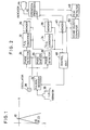
- the ultrasonic diagnostic equipment embodying the present invention includes an ultrasonic transducer 20 which, is energized by a pulser 22 to, transmit an ultrasonic pulse with certain spread, and receive the reflected wave of the ultrasonic pulse from a reflector.
- the reflected signal is amplified to a required level via a receiver.
- Phase detectors 24 and 26 detect the phase shifts of the received signal by accepting each of the two signals with phase difference of 90° which consist of a sine wave signal supplied by an oscillator 28 and another sine wave signal that is obtained by shifting the phase of the wave from the oscillator 28 by 90° through a phase shifter 30.
- the sine wave signals are set to have a frequency which is equal to the resonance frequency of the ultrasonic transducer 20, and the high frequency components of the signals whose phase shifts are detected have been removed by the low-pass filter which is fuilt in the detector when they are output.
- a cosine hologram signal and a sine hologram signal which are mutually orthogonal. After they are each digitized via the A/ D converters 32 and 34 they are stored in memories 36 and 38.
- a memory 40 memorizes a plurality of kernel signals corresponding to the various values of the depth 2 as a parameter.
- An operation processing unit 42 a microprocessor carries out the operational process for synthetic aperture indicated by Eq.(6) based on the information coming from the memories 36, 38, and 40, and displays the reconstructed image A thus obtained on an indicator 44. At the sametime, the operation processing unit 42 detects the maximum value of the amplitude, and transfers the data to a peak detector 46.
- a control unit 48 is adapted for supplying the peak detector 46 with the variations in the maximum value of the recorded image which are obtained by feeding the kernel signal to the operation processing unit 42 in succession, and controls a series of actions of the various parts involved in this operation.
- the peak detector 46 there carry out the detection of the largest maximum value in the amplitude of the reconstructed image obtained by varying the depth of the kernel signal, and the corresponding depth z' of the kernel signal is transferred to a sound valocity computer 50.
- the sound velocity computer 50 At the sound velocity computer 50, the velocity of the ultrasonic wave is computed by the use of Eq. (8), and the result is displayed.
- the computation of the velocity of the ultrasonic wave according to the present device is easy, and the method is very effective.
Landscapes
- Physics & Mathematics (AREA)
- Engineering & Computer Science (AREA)
- General Physics & Mathematics (AREA)
- Radar, Positioning & Navigation (AREA)
- Remote Sensing (AREA)
- Computer Networks & Wireless Communication (AREA)
- Acoustics & Sound (AREA)
- Ultra Sonic Daignosis Equipment (AREA)
- Investigating Or Analyzing Materials By The Use Of Ultrasonic Waves (AREA)
Applications Claiming Priority (2)
| Application Number | Priority Date | Filing Date | Title |
|---|---|---|---|
| JP25983/84 | 1984-02-16 | ||
| JP59025983A JPS60171037A (ja) | 1984-02-16 | 1984-02-16 | 超音波診断装置 |
Publications (2)
| Publication Number | Publication Date |
|---|---|
| EP0152113A1 true EP0152113A1 (fr) | 1985-08-21 |
| EP0152113B1 EP0152113B1 (fr) | 1989-06-07 |
Family
ID=12180949
Family Applications (1)
| Application Number | Title | Priority Date | Filing Date |
|---|---|---|---|
| EP85101628A Expired EP0152113B1 (fr) | 1984-02-16 | 1985-02-14 | Appareil diagnostic à ultrasons |
Country Status (5)
| Country | Link |
|---|---|
| US (1) | US4633883A (fr) |
| EP (1) | EP0152113B1 (fr) |
| JP (1) | JPS60171037A (fr) |
| CA (1) | CA1226663A (fr) |
| DE (1) | DE3570929D1 (fr) |
Cited By (1)
| Publication number | Priority date | Publication date | Assignee | Title |
|---|---|---|---|---|
| EP0226466A3 (en) * | 1985-12-13 | 1987-10-14 | Matsushita Electric Industrial Co., Ltd. | Ultrasonic diagnostic apparatus based on variations of acoustic characteristic |
Families Citing this family (9)
| Publication number | Priority date | Publication date | Assignee | Title |
|---|---|---|---|---|
| DE3865034D1 (de) * | 1987-02-09 | 1991-10-31 | Matsushita Electric Industrial Co Ltd | Ultraschall-untersuchungsgeraet. |
| US4852577A (en) * | 1988-04-07 | 1989-08-01 | The United States Of America As Represented By The Department Of Health And Human Services | High speed adaptive ultrasonic phased array imaging system |
| US5201715A (en) * | 1991-11-19 | 1993-04-13 | Mcghan Medical Corporation | Implantable devices having ultrasonic echographic signature |
| US5283672A (en) * | 1992-05-04 | 1994-02-01 | Rockwell International Corporation | Holographic techniques for generating high resolution telescopic images |
| US5331964A (en) * | 1993-05-14 | 1994-07-26 | Duke University | Ultrasonic phased array imaging system with high speed adaptive processing using selected elements |
| US6208181B1 (en) * | 1998-01-14 | 2001-03-27 | Intel Corporation | Self-compensating phase detector |
| US6014897A (en) * | 1998-09-02 | 2000-01-18 | Mo; Larry Y. L. | Method and apparatus for improving sidelobe performance of sparse array using harmonic imaging |
| KR100875203B1 (ko) * | 2005-12-28 | 2008-12-19 | 주식회사 메디슨 | 초음파 영상의 획득 방법 |
| CN106725610B (zh) * | 2016-11-29 | 2019-08-06 | 深圳大学 | 基于移动声束相干激励剪切波的弹性测量方法及系统 |
Citations (2)
| Publication number | Priority date | Publication date | Assignee | Title |
|---|---|---|---|---|
| US3885224A (en) * | 1972-02-24 | 1975-05-20 | Carl N Klahr | Signal processing apparatus for imaging scanner |
| EP0110621A2 (fr) * | 1982-11-20 | 1984-06-13 | Kabushiki Kaisha Toshiba | Système de traitement de signaux d'image basé sur la technique d'ouverture synthétique |
Family Cites Families (2)
| Publication number | Priority date | Publication date | Assignee | Title |
|---|---|---|---|---|
| US4170142A (en) * | 1977-07-15 | 1979-10-09 | Electric Power Research Institute, Inc. | Linear transducer array and method for both pulse-echo and holographic acoustic imaging |
| US4531411A (en) * | 1983-10-25 | 1985-07-30 | The United States Of America As Represented By The United States Department Of Energy | Acoustic emission linear pulse holography |
-
1984
- 1984-02-16 JP JP59025983A patent/JPS60171037A/ja active Pending
-
1985
- 1985-02-05 CA CA000473621A patent/CA1226663A/fr not_active Expired
- 1985-02-08 US US06/699,674 patent/US4633883A/en not_active Expired - Fee Related
- 1985-02-14 DE DE8585101628T patent/DE3570929D1/de not_active Expired
- 1985-02-14 EP EP85101628A patent/EP0152113B1/fr not_active Expired
Patent Citations (2)
| Publication number | Priority date | Publication date | Assignee | Title |
|---|---|---|---|---|
| US3885224A (en) * | 1972-02-24 | 1975-05-20 | Carl N Klahr | Signal processing apparatus for imaging scanner |
| EP0110621A2 (fr) * | 1982-11-20 | 1984-06-13 | Kabushiki Kaisha Toshiba | Système de traitement de signaux d'image basé sur la technique d'ouverture synthétique |
Non-Patent Citations (4)
| Title |
|---|
| ACOUSTICAL IMAGING, London, 19th-22nd July 1982, vol. 12, pages 479-491, edited by E.A. Ash and C.R. Hill, Plenum Press, New York, US; P.R. MESDAG et al.: "An approach to tissue characterization based on wave theory using a new velocity analysis technique" * |
| IEEE TRANSACTIONS ON SONICS AND ULTRASONICS, vol. SU-27, no. 5, September 1980, pages 249-252, New York, US; E.E. HUNDT et al.: "Digital processing of ultrasonic data by deconvolution" * |
| PATENTS ABSTRACTS OF JAPAN, vol. 8, no. 211 (P-303)[1648], 26th September 1984; & JP - A - 59 94091 (TOSHIBA K.K.) 30-05-1984 * |
| ULTRASONICS, vol. 11, no. 5, September 1973, pages 223-226, Guildford, GB; J. JELLINS et al.: "Velocity compensation in water-coupled breast echography" * |
Cited By (3)
| Publication number | Priority date | Publication date | Assignee | Title |
|---|---|---|---|---|
| EP0226466A3 (en) * | 1985-12-13 | 1987-10-14 | Matsushita Electric Industrial Co., Ltd. | Ultrasonic diagnostic apparatus based on variations of acoustic characteristic |
| US4817615A (en) * | 1985-12-13 | 1989-04-04 | Matsushita Electric Industrial Co., Ltd. | Ultrasonic temperature measurement apparatus |
| EP0406915A1 (fr) * | 1985-12-13 | 1991-01-09 | Matsushita Electric Industrial Co., Ltd. | Appareil diagnostique à ultrasons se basant sur les variations d'une caractéristique acoustique |
Also Published As
| Publication number | Publication date |
|---|---|
| JPS60171037A (ja) | 1985-09-04 |
| US4633883A (en) | 1987-01-06 |
| DE3570929D1 (en) | 1989-07-13 |
| CA1226663A (fr) | 1987-09-08 |
| EP0152113B1 (fr) | 1989-06-07 |
Similar Documents
| Publication | Publication Date | Title |
|---|---|---|
| EP0226466B1 (fr) | Appareil diagnostique à ultrasons se basant sur les variations d'une caractéristique acoustique | |
| KR900002200B1 (ko) | 탐사방법 및 장치 | |
| EP0076168B1 (fr) | Système de caractérisation d'un milieu au moyen des ondes ultrasonores | |
| EP0147955B1 (fr) | Système de mesure d'un paramètre non-linéaire par ultrasons | |
| JP2849159B2 (ja) | 超音波診断装置 | |
| EP0146073B1 (fr) | Appareil de diagnostic à ultrasons | |
| US4873869A (en) | Device for the scanning of objects by means of ultrasound echography | |
| JPS62133944A (ja) | 超音波エコ−グラフイ装置 | |
| EP0152113A1 (fr) | Appareil diagnostic à ultrasons | |
| US4446737A (en) | Method and device for measuring objects using ultrasound echography | |
| EP0212899A2 (fr) | Essai de matériaux aux ultra-sons | |
| JPS62204733A (ja) | 超音波ドプラ診断装置 | |
| JPS6111659A (ja) | 超音波検査装置 | |
| US4676251A (en) | Improved method and device for measuring frequency dependent parameters of objects by means of ultrasound echography | |
| RU2039368C1 (ru) | Способ измерения расстояния и устройство для его осуществления | |
| WO1989004975A1 (fr) | Transducteur pour loch acoustique | |
| US5239516A (en) | Ultrasonic ground speedometer utilizing doppler effect of ultrasonic waves | |
| GB2188420A (en) | Ultrasonic range finding | |
| US4794546A (en) | Method of and apparatus for scanning objects by means of ultrasound echography | |
| JPH02203849A (ja) | パルスドプラ計測装置 | |
| JPH0696013B2 (ja) | 超音波計測装置 | |
| JPH0620453B2 (ja) | 超音波ドプラ装置 | |
| JPH066124B2 (ja) | 超音波計測装置 | |
| JPS62226027A (ja) | 超音波計測装置 | |
| JPH0775604B2 (ja) | 生体内温度測定装置 |
Legal Events
| Date | Code | Title | Description |
|---|---|---|---|
| PUAI | Public reference made under article 153(3) epc to a published international application that has entered the european phase |
Free format text: ORIGINAL CODE: 0009012 |
|
| 17P | Request for examination filed |
Effective date: 19850214 |
|
| AK | Designated contracting states |
Designated state(s): DE FR GB NL |
|
| 17Q | First examination report despatched |
Effective date: 19871228 |
|
| GRAA | (expected) grant |
Free format text: ORIGINAL CODE: 0009210 |
|
| AK | Designated contracting states |
Kind code of ref document: B1 Designated state(s): DE FR GB NL |
|
| PG25 | Lapsed in a contracting state [announced via postgrant information from national office to epo] |
Ref country code: NL Effective date: 19890607 |
|
| REF | Corresponds to: |
Ref document number: 3570929 Country of ref document: DE Date of ref document: 19890713 |
|
| ET | Fr: translation filed | ||
| NLV1 | Nl: lapsed or annulled due to failure to fulfill the requirements of art. 29p and 29m of the patents act | ||
| PLBE | No opposition filed within time limit |
Free format text: ORIGINAL CODE: 0009261 |
|
| STAA | Information on the status of an ep patent application or granted ep patent |
Free format text: STATUS: NO OPPOSITION FILED WITHIN TIME LIMIT |
|
| 26N | No opposition filed | ||
| PGFP | Annual fee paid to national office [announced via postgrant information from national office to epo] |
Ref country code: GB Payment date: 19960205 Year of fee payment: 12 |
|
| PGFP | Annual fee paid to national office [announced via postgrant information from national office to epo] |
Ref country code: FR Payment date: 19970211 Year of fee payment: 13 |
|
| PG25 | Lapsed in a contracting state [announced via postgrant information from national office to epo] |
Ref country code: GB Effective date: 19970214 |
|
| PGFP | Annual fee paid to national office [announced via postgrant information from national office to epo] |
Ref country code: DE Payment date: 19970221 Year of fee payment: 13 |
|
| GBPC | Gb: european patent ceased through non-payment of renewal fee |
Effective date: 19970214 |
|
| PG25 | Lapsed in a contracting state [announced via postgrant information from national office to epo] |
Ref country code: FR Free format text: THE PATENT HAS BEEN ANNULLED BY A DECISION OF A NATIONAL AUTHORITY Effective date: 19980228 |
|
| PG25 | Lapsed in a contracting state [announced via postgrant information from national office to epo] |
Ref country code: DE Free format text: LAPSE BECAUSE OF NON-PAYMENT OF DUE FEES Effective date: 19981103 |
|
| REG | Reference to a national code |
Ref country code: FR Ref legal event code: ST |