EP0152171A2 - Flasche und deren Stopfen - Google Patents
Flasche und deren Stopfen Download PDFInfo
- Publication number
- EP0152171A2 EP0152171A2 EP85300165A EP85300165A EP0152171A2 EP 0152171 A2 EP0152171 A2 EP 0152171A2 EP 85300165 A EP85300165 A EP 85300165A EP 85300165 A EP85300165 A EP 85300165A EP 0152171 A2 EP0152171 A2 EP 0152171A2
- Authority
- EP
- European Patent Office
- Prior art keywords
- bottle
- stopper
- tethers
- ring
- flange
- Prior art date
- Legal status (The legal status is an assumption and is not a legal conclusion. Google has not performed a legal analysis and makes no representation as to the accuracy of the status listed.)
- Ceased
Links
- 239000007788 liquid Substances 0.000 claims abstract description 20
- 239000004033 plastic Substances 0.000 claims abstract description 9
- 229920003023 plastic Polymers 0.000 claims abstract description 9
- XLYOFNOQVPJJNP-UHFFFAOYSA-N water Substances O XLYOFNOQVPJJNP-UHFFFAOYSA-N 0.000 claims description 6
- 230000000717 retained effect Effects 0.000 claims description 3
- 235000019993 champagne Nutrition 0.000 abstract description 9
- 230000006378 damage Effects 0.000 abstract description 5
- 235000015040 sparkling wine Nutrition 0.000 abstract description 5
- 208000027418 Wounds and injury Diseases 0.000 abstract 1
- 208000014674 injury Diseases 0.000 abstract 1
- 210000003739 neck Anatomy 0.000 description 64
- 239000007799 cork Substances 0.000 description 60
- 230000014759 maintenance of location Effects 0.000 description 8
- 238000000465 moulding Methods 0.000 description 8
- 235000014101 wine Nutrition 0.000 description 6
- 230000008878 coupling Effects 0.000 description 5
- 238000010168 coupling process Methods 0.000 description 5
- 238000005859 coupling reaction Methods 0.000 description 5
- 238000003780 insertion Methods 0.000 description 5
- 230000037431 insertion Effects 0.000 description 5
- 230000009471 action Effects 0.000 description 4
- 230000008901 benefit Effects 0.000 description 3
- 238000010276 construction Methods 0.000 description 3
- 239000011888 foil Substances 0.000 description 3
- 238000002347 injection Methods 0.000 description 3
- 239000007924 injection Substances 0.000 description 3
- 239000000463 material Substances 0.000 description 3
- 230000007246 mechanism Effects 0.000 description 3
- 239000002184 metal Substances 0.000 description 3
- 230000000452 restraining effect Effects 0.000 description 3
- CURLTUGMZLYLDI-UHFFFAOYSA-N Carbon dioxide Chemical compound O=C=O CURLTUGMZLYLDI-UHFFFAOYSA-N 0.000 description 2
- 235000013334 alcoholic beverage Nutrition 0.000 description 2
- 235000014171 carbonated beverage Nutrition 0.000 description 2
- 230000000052 comparative effect Effects 0.000 description 2
- 230000000694 effects Effects 0.000 description 2
- 238000001746 injection moulding Methods 0.000 description 2
- 229920000092 linear low density polyethylene Polymers 0.000 description 2
- 239000004707 linear low-density polyethylene Substances 0.000 description 2
- -1 polyethylene Polymers 0.000 description 2
- 239000011347 resin Substances 0.000 description 2
- 229920005989 resin Polymers 0.000 description 2
- 229920001169 thermoplastic Polymers 0.000 description 2
- 239000012815 thermoplastic material Substances 0.000 description 2
- 239000004416 thermosoftening plastic Substances 0.000 description 2
- 230000032258 transport Effects 0.000 description 2
- WNEODWDFDXWOLU-QHCPKHFHSA-N 3-[3-(hydroxymethyl)-4-[1-methyl-5-[[5-[(2s)-2-methyl-4-(oxetan-3-yl)piperazin-1-yl]pyridin-2-yl]amino]-6-oxopyridin-3-yl]pyridin-2-yl]-7,7-dimethyl-1,2,6,8-tetrahydrocyclopenta[3,4]pyrrolo[3,5-b]pyrazin-4-one Chemical compound C([C@@H](N(CC1)C=2C=NC(NC=3C(N(C)C=C(C=3)C=3C(=C(N4C(C5=CC=6CC(C)(C)CC=6N5CC4)=O)N=CC=3)CO)=O)=CC=2)C)N1C1COC1 WNEODWDFDXWOLU-QHCPKHFHSA-N 0.000 description 1
- 208000020564 Eye injury Diseases 0.000 description 1
- 208000028771 Facial injury Diseases 0.000 description 1
- 239000004698 Polyethylene Substances 0.000 description 1
- 230000001133 acceleration Effects 0.000 description 1
- 230000004323 axial length Effects 0.000 description 1
- 235000013361 beverage Nutrition 0.000 description 1
- 230000009172 bursting Effects 0.000 description 1
- 230000000981 bystander Effects 0.000 description 1
- 229910002092 carbon dioxide Inorganic materials 0.000 description 1
- 239000001569 carbon dioxide Substances 0.000 description 1
- 230000008859 change Effects 0.000 description 1
- 230000001427 coherent effect Effects 0.000 description 1
- 239000002131 composite material Substances 0.000 description 1
- 230000006835 compression Effects 0.000 description 1
- 238000007906 compression Methods 0.000 description 1
- 230000007547 defect Effects 0.000 description 1
- 230000002950 deficient Effects 0.000 description 1
- 230000000994 depressogenic effect Effects 0.000 description 1
- 238000006073 displacement reaction Methods 0.000 description 1
- 230000035622 drinking Effects 0.000 description 1
- 238000000605 extraction Methods 0.000 description 1
- 230000001815 facial effect Effects 0.000 description 1
- 238000000855 fermentation Methods 0.000 description 1
- 230000004151 fermentation Effects 0.000 description 1
- 229920002457 flexible plastic Polymers 0.000 description 1
- 239000012530 fluid Substances 0.000 description 1
- 239000011521 glass Substances 0.000 description 1
- 238000011194 good manufacturing practice Methods 0.000 description 1
- 230000005484 gravity Effects 0.000 description 1
- 238000007689 inspection Methods 0.000 description 1
- 238000002372 labelling Methods 0.000 description 1
- 238000004519 manufacturing process Methods 0.000 description 1
- 239000002991 molded plastic Substances 0.000 description 1
- 229920000573 polyethylene Polymers 0.000 description 1
- 229920002635 polyurethane Polymers 0.000 description 1
- 239000004814 polyurethane Substances 0.000 description 1
- 230000002265 prevention Effects 0.000 description 1
- 238000005204 segregation Methods 0.000 description 1
- 230000009528 severe injury Effects 0.000 description 1
- 230000035939 shock Effects 0.000 description 1
- 239000000126 substance Substances 0.000 description 1
Images




Classifications
-
- B—PERFORMING OPERATIONS; TRANSPORTING
- B65—CONVEYING; PACKING; STORING; HANDLING THIN OR FILAMENTARY MATERIAL
- B65D—CONTAINERS FOR STORAGE OR TRANSPORT OF ARTICLES OR MATERIALS, e.g. BAGS, BARRELS, BOTTLES, BOXES, CANS, CARTONS, CRATES, DRUMS, JARS, TANKS, HOPPERS, FORWARDING CONTAINERS; ACCESSORIES, CLOSURES, OR FITTINGS THEREFOR; PACKAGING ELEMENTS; PACKAGES
- B65D39/00—Closures arranged within necks or pouring openings or in discharge apertures, e.g. stoppers
- B65D39/0005—Closures arranged within necks or pouring openings or in discharge apertures, e.g. stoppers made in one piece
- B65D39/0017—Injection-molded plastic closures for "Champagne"- or "Sekt"-type bottles
-
- B—PERFORMING OPERATIONS; TRANSPORTING
- B65—CONVEYING; PACKING; STORING; HANDLING THIN OR FILAMENTARY MATERIAL
- B65D—CONTAINERS FOR STORAGE OR TRANSPORT OF ARTICLES OR MATERIALS, e.g. BAGS, BARRELS, BOTTLES, BOXES, CANS, CARTONS, CRATES, DRUMS, JARS, TANKS, HOPPERS, FORWARDING CONTAINERS; ACCESSORIES, CLOSURES, OR FITTINGS THEREFOR; PACKAGING ELEMENTS; PACKAGES
- B65D55/00—Accessories for container closures not otherwise provided for
- B65D55/16—Devices preventing loss of removable closure members
-
- B—PERFORMING OPERATIONS; TRANSPORTING
- B65—CONVEYING; PACKING; STORING; HANDLING THIN OR FILAMENTARY MATERIAL
- B65D—CONTAINERS FOR STORAGE OR TRANSPORT OF ARTICLES OR MATERIALS, e.g. BAGS, BARRELS, BOTTLES, BOXES, CANS, CARTONS, CRATES, DRUMS, JARS, TANKS, HOPPERS, FORWARDING CONTAINERS; ACCESSORIES, CLOSURES, OR FITTINGS THEREFOR; PACKAGING ELEMENTS; PACKAGES
- B65D59/00—Plugs, sleeves, caps, or like rigid or semi-rigid elements for protecting parts of articles or for bundling articles, e.g. protectors for screw-threads, end caps for tubes or for bundling rod-shaped articles
Definitions
- the present invention generally relates to bottles for pressurized carbonated water-based liquid contents, such as champagne and sparkling wines, and to stoppers for such bottles.
- an improved stoppering arrangement in which a plastic stopper is connected by a single tether to a ring, the cork, the tether and the ring being molded in one piece as a unit, the ring being forced over an upper flange on the neck of a bottle near the mouth and the ring being capable of being manually forced over a second lower flange.
- the single tether is in a folded state, as molded, and the folded tether is so physically disposed at the time of molding that its radial position with respect to the axis of symmetry of the stopper does not extend beyond the ring prior to and after insertion of the stopper in the bottle neck.
- the single folded tether is connected to the head of the stopper and to the ring by frangible bridges so as to retain the tether in a folded state and the unit in a compact condition prior to insertion of the stopper into the bottle neck.
- frangible bridges break upon insertion of the stopper into the neck of the bottle and forcing of the ring over the flange on the neck of the bottle so that when the stopper is loosened prior to its extraction from the neck of the bottle, it is not free to be ejected forcefully and unrestrainedly but rather will be checked in its flight, if any, from the bottle by the tether.
- the stopper might fly free and injure the person opening the bottle or a person nearby. Although this was a rather rare occurrence, the liability could be substantial and it was not an event which a bottler could disregard. A bottler wants to be assured that the stopper would never be able to be freely propelled from the bottle under any circumstances.
- champagne and sparkling wines sometimes will be stored in places which are not refrigerated and where temperatures may be quite high so that even if the stopper were not loosened, it might work its way partially out of the neck of the bottle and, if the single tether were not strong enough to restrain it, it would pop out and might strike someone passing by.
- Still another object of this invention is to provide a closure arrangement of the character described which allows stoppering of bottles by unskilled laborers.
- This invention includes, for use with a bottle containing pressurized carbonated water based liquid contents and having a body portion, an elongated neck portion, and a mouth portion;
- the bottle has an elongated neck and two axially spaced squat annular flanges on the neck adjacent to its mouth, although the invention will function satisfactorily with only one such flange.
- a stopper unit which in a preferred embodiment, includes a stopper, twin folded tethers, and a ring, all injection molded as one piece of thermoplastic material.
- the ring is a receivable between the two annular flanges, i.e. below the top flange of the bottle neck.
- the plastic is elastomeric and the ring is so dimensioned that the inner diameter thereof as-molded is slightly smaller than the outer diameter of the uppermost flange so that it can be pushed down by machine over this flange, expanding as it does so and contracting°to a small diameter after it has passed the uppermost flange, whereby the ring will be anchored between the two flanges or, if only one flange is provided, it will be anchored below that flange.
- the lower flange preferably has a slightly larger outer diameter than the upper flange, for a reason that will be described hereinafter.
- the stopper has an enlarged head to facilitate manual gripping and manipulation thereof, and the stopper is frictionally receivable in the mouth and neck of a bottle to form a tight closure therefor, which is a push fit, i.e. tight enough for the stopper to remain in the neck of the bottle and resist the internal pressure generated by the carbonated liquid contents when at ordinary room temperatures, e.g. about 20 0 C.
- the stopper will not be accidentally forced out of the bottle by gas pressure during storage, transport, or handling of the bottle, particularly if the bottle is subjected to temperatures high enough to generate an internal gas pressure that might suffice to force the stopper out of the bottle inadvertently.
- the shank of the stopper may also include annular ridges to increase the frictional contact between it and the inner surface of the bottle neck.
- Each tether is connected at one end to a different point on the head of the stopper and at its other end to a different point on the ring.
- the points of connection of the tethers to the head of the stopper are spaced angularly apart, as are the points of connection of the other ends of the tethers to the ring.
- the mid-points of the folded tethers are adjacent to one another and are interconnected by an energy-absorbing link. More specifically, each tether is in a fully collapsed state as molded, each tether being singly folded, i.e. having two branches connected by a retroverted bend to form a narrow 'U' of which the two arms are substantially parallel as molded. The two bends face away from one another but their closed ends are near together, a typical spacing being in the order of 3/16 of an inch.
- the branches are arcuate in plan and are oriented with their centers of curvature coincident with the axis of symmetry of the bottle neck.
- a plurality of frangible bridges may connect the two parallel arms of each folded tether to one another and/or to the head of the stopper and/or to the ring, the purpose of these bridges being to assist in holding the folded tethers in their as-molded configurations.
- the radial orientations of the tethers are such that the tethers do not extend radially beyond the ring and, preferably, not beyond the radius of the head of the stopper so that when the stop- per/tether/ring units are in a random mass in a hopper, they will not tend to become entangled and can be easily separated from one another in an automatic feeding device.
- the bottle and its contents have been chilled so that the pressure of the gas in the head space is not excessive and the stopper can be partially or fully withdrawn with safety after the wire retention means or the bail has been removed.
- a typical such bottle is charged with approximately 4.7 to 5.8 volumes of carbon dioxide per volume of liquid alcoholic beverage,resulting in a gas pressure in the head space of a stoppered bottle of about 70 to 80 PSIG at a temperature of about 68 0 F. This corresponds to a pressure of about 45 PSIG at a temperature of about 40 to 45 0 F.
- this operation is customarily performed at a temperature of about 35 0 F, at which time the prevailing charging pressure is approximately 35 to 40 PSIG.
- the temperature to which a charged and filled bottle is subjected after it is shipped from the factory cannot be controlled, although the bottler may suggest a modicum of care.
- Such care certainly is desirable because at a temperature of about 90°F the interior pressure in the bottle rises to about 105 PSIG, and at a temperature of about 100°F it reaches about 110 PSIG, while at about 110°F it becomes about 120 PSIG.
- the internal pressure is still higher, attaining a peak of about 130 PSIG and may go even somewhat higher with shaking to which an unwary consumer may subject a bottle, particularly if slightly intoxicated. At this stage the stopper becomes a dangerous instrument.
- the tethers in their as-molded condition are so situated that they are asymetrically located with respect to the axis of symmetry;, i.e. the longitudinal axis, of the neck of the bottle, so that when the stopper does spring out of the mouth of the bottle it will not tend to interfere with the free flow of the stream of liquid as it is poured from the bottle.
- the reference numeral 20 denotes a plant for filling and stoppering bottles with liquid, specifically an aqueous carbonated liquid under pressure, a typical pressure being in the order of 70-80 PSIG at room temperature, after filling.
- liquid specifically an aqueous carbonated liquid under pressure
- a typical pressure being in the order of 70-80 PSIG at room temperature, after filling.
- a particular embodiment with which the invention is practiced is that of domestic, i.e. U.S., champagnes.
- a typical plant 20 includes three operational stations 22, 24 and 26.
- empty bottles 28 which previously have been cleaned and dried are fed, usually automatically, onto a rotary carrier from a line 30, the rotary carrier being denoted by the reference numeral 32.
- the carrier 32 intermittently advances the bottles to and past one or plural filling heads 34, e.g. nozzles, which, when the bottle or bottles are stationary, feed carbonated beverages under pressure into the bottles beneath the heads in predetermined volumes, leaving suitable headspace.
- the carrier 32 then shifts the filled bottles back onto the line 30 which transports them to the station-24 at which there is another intermittently rotatable carrier 36 that brings the filled bottles to and past one or plural cork unit-inserting heads 38.
- a stopper/tethers/ring/cork/unit 40 such as is inserted by the head 38 into bottle after filled bottle, is shown in FIG. 2, this being a cork unit the structure of which prior to and after assembly onto a filled bottle is a feature of the present invention and will be described in considerable detail subsequently.
- a shank of such a unit 40 simply is inserted into the neck of a filled bottle, but the coupling of the unit with the bottle is not as yet completed, this being left for the following station 26.
- cork unit-inserting heads 38 which can, if plural such heads are provided, operate in unison each time that the rotary carrier 36 halts its intermittent rotation.
- the corked bottles are discharged back onto the line 30 which carries them to the station 26 where the cork unit is further coupled to its associated bottle by a ring/flange connection which will be detailed at a following point of this description.
- the purpose of this ring/flange interengagement is to captively tether the cork unit to the bottle so that when, at a subsequent point in time and place, a user starts to pull the cork unit out of the neck of the bottle and'when circumstances might combine to cause the stopper to shoot out of the neck of the bottle and harm the user or someone nearby, the safety feature provided by the tether, the ring, and the bottle flange prevents this from happening.
- the bottles are delivered back onto the line 30 for further handling which will usually constitute the application of a wire restraint cage or bail over the cork unit as a precautionary measure and, frequently, the wrapping of decorative foil and labelling for esthetic and commercial purposes.
- the cork unit 40 is a composite, that is to say a unit composed of several parts which are molded of a plastic, usually an elastomeric thermoplastic material, as a single piece, the unit being illustrated in FIGs. 2, 3 and 4 in its as-molded condition. At this time the unit 40 includes three essential components which are:
- the stopper, the tether(s) and the ring are molded in one piece from plastic, that is to say that they are a one piece unit and that they occupy the relative position which are clearly illustrated in FIGs. 3 and 4 and will now be described in some detail.
- the stopper 42 is a tubular cylindrical sleeve 48 which is open at its lower end 50 as a matter of molding convenience and includes a crown 52 which provides a closed upper end to maintain the requisite carbonation pressure within a stoppered bottle.
- a suitable material for the unit 40 is an injection molded elastomeric thermoplastic such as polyethylene.
- the crown may be formed with a shallow recess 54 to receive a manufacturer's or a product identification label (not shown).
- the stopper head is enlarged by the inclusion of radially extending circumferentially spaced ribs 56 which provide a good grip to be engaged by a user's hands when it is desired to rotate and pull the stopper from the neck of a bottle in which it is inserted.
- the lower external surface of the sleeve 48 has molded thereon a series, e.g. four, spaced squat annular rings 58, that insure tight frictional engagement of the sleeve with the inner surface of the neck of the bottle, bearing in mind that the molding tolerances for glass bottles are not particularly close, nor is the molding tolerance for injection molded plastic parts.
- the sleeve is elastomeric and because the rings 58 are of slight axial length and radial height, the sleeve is able to be radially compressed with comparative ease to tolerate dimensional variances in molding and still obtain a good frictional fit between the stopper sleeve and the bottle neck sufficient to enable the stopper to be held firmly in place against the gas pressure in the bottle once the stopper has been pushed tightly into the bottle neck.
- the lower end of the stopper 42 is chamfered, as at 60, to ease its entry into the mouth of a bottle.
- tether 44 this has been described in the singular, i.e. as "a" tether; in actuality, in the cork unit 40 shown in FIGs. 2 through 4 now being described there are four tethers 62, 64, 66 and 68. These tethers are arranged in pairs, which is to say the tethers 62 and 64 form one pair which mutually act conjointly and the tethers 66 and 68 form another pair which mutually act conjointly. More particularly, the tether 62 (see FIG. 2) is in the shape of a narrow "U” with a retroverted bend 70 and two parallel branches 72 and 74.
- this tether 62 in plan, it is of arcuate configuration and it is approximately in registry with the outer ends of the ribs 56 of the head 38 of the sleeve 48.
- the lower ends of the sleeves ribs 56 terminate at a circular disk 76 whose radius equals that of the lower ends of said ribs and the outer sides of the arcuate tether 62 are approximately in vertical registry with the associated portion of the overlying part of this disk (see FIG. 3).
- the tether 62 in its as-molded condition does not extend radially beyond the head 38 of the stopper. Actually, it is positioned at just about the outer radial boundary of the head of the stopper. The same holds true of all of the tethers 62, r '64, 66 and 68; that is to say, they all are arcuate and all are in approximate registry with their associated portions of the overlying parts of the disk 76.
- the ring 46 is arranged concentrically with the sleeve 48, concentrically with the disk 76 and concentrically with the arcuate tethers 62, 64, 66, 68. However the ring 46 is located below, specifically a short distance below, the lower branches 74 of the tethers 62, 64, 66, 68. This spacing is quite clearly shown in FIGs. 2, 3 and 4.
- Common zones such as those 78, 80 mentioned with respect to the tethers 62, 64 also are provided for the tethers 66, 68.
- the common zones 78, 80 for the tethers 62, 64 are substantially diametrically opposed (on the disk 76 and the ring 46) with respect to the common zones for the tethers 66, 68 on the disk 76 and the ring 46 so that the ring and the head 38 of the cork are in effect connected by four tethers arranged in two pairs, each pair having a common upper end at the head of the stopper and a common lower end at the ring, these ends being spaced substantially 180 0 apart at the head of the stopper and at the ring. This 180 0 spacing is not essential but does provide a neat symmetrical appearance and encourages uniform flow of molten thermoplastic during a molding cycle.
- positions of the tethers refer to their as-molded positions and these are positions the tethers will occupy as the units 40 are handled prior to coupling with bottles. There will be displacements from these positions as will be pointed out subsequently when the sleeves 48 are inserted in bottles and there will be a further change when the stopper 42 is removed from a bottle by a user. All of this remains for later description.
- frangible bridges are employed to aid in holding the tethers 62, 64, 66, 68 in their as-molded folded arcuate positions within the confines of an imaginery cone extending from the periphery of the disk 76 to the periphery of the ring 46, these being the positions that they occupy at the time of their molding.
- the frangible bridges may include bridges 82 (see FIGs. 2 and 4) spanning the narrow gap between the center points of the folded pairs of tethers 62, 64 and 66, 68. These bridges are sufficiently strong to withstand the minor stresses imposed thereon during handling of the cork units 40 but not to withstand any substantial tensile force urging apart the head 38 and the ring 46.
- the common zones 78, 80 also act to anchor the centers of the tethers in their as-molded positions but do not function to control the positions of the intermediate portions of the tethers when the tethers are stretched, an action to which it will be seen they are subjected during certain steps of the coupling operation and during uncorking of a bottle.
- additional bridges which are not employed in the cork unit 40 here illustrated and described, may be employed to interconnect the branches of the sundry tethers either to the undersurface of the overlying disk 76 or to the upper surface of the underlying ring 46.
- auxiliary bridges may be employed to interconnect the parallel branches of individual tethers to one another at one or more intermediate points of their lengths.
- additional bridges i.e. bridges between the branches of the tethers and the disk, the bridges between the tethers and the ring, and the bridges of the parallel branches of individual tethers to one another are not employed because there are additional elements which are provided for a purpose other than that of maintaining the tethers in their as-molded positions.
- additional elements although aiding maintaining the tethers in their as-molded positions, have a more important function.
- These additional elements are energy-absorbing links 84 which are a principal feature of the present invention and are employed to interconnect the rear (outer) surfaces of adjacent retroverted bends of sets of tethers.
- the tethers which cooperate in the practice of the present invention are “sets” of oppositely folded tethers the retroverted bends of which have their rear (i.e., back or outer) surfaces adjacent (close by) and facing each other and connected by an energy-absorbing link 84, that is to say a "set” of tethers as so-called in the present invention is a set of tethers of which one tether runs from a point on the disk 76 to a point on the ring 46, these two points usually being in a plane which includes the axis of symmetry of the sleeve 48, although not necessarily so.
- the other tether of the same set as the tether the retroverted bend of which has its rear surface facing the retroverted bend of the first tether of the same set and this second tether of the set likewise runs from a point on a disk to a point on the ring. Again the two points preferably . lie in a common axial plane. If there are two sets of tethers in a cork unit 40, as is the case with the unit 40 shown in FIG.s 2-4 there is a common point for one tether of each set on the disk, this being the point 78 and a common point for the other tether of each set on the ring, this being the point 80.
- the frangible bridges e.g. the bridges 82
- the energy-absorbing links 84 are sturdier than the frangible bridges. They are sufficiently sturdy so that when a tensile force is exerted on a cork unit tending to spread apart the head 38 from the ring 46 and thereby somewhat to straighten out the tethers of a "set",the links 84 will not rupture. They are strong enough to resist the engendered tensile force. Such force is, however, applied to the energy absorbing links tend to and actually do stretch the same and in so doing some of the energy which moves the head apart from the ring.
- the links 84 may break, depending upon the pressure of the gas in the head space of the bottle. But by the time the energy-absorbing links have reached their bursting points the acceleration of the stopper will have been sufficiently retarded so that the stopper will be checked in its flight by the tethers and will not fly freely to strike and damage nearby people.
- Polyethelene lends itself to injection molding of complex shapes such as that of the aforesaid cork 40.
- a grade of polyethelene which works well for accomplishing the present invention is a linear low density polyethylene sold by the Dow Chemical Corporation under the trademark, Dowlex 2535 resin for injection molding -- LLDPE. This resin has the following typifying characteristics:
- energy-absorbing links 84 with two sets of tethers or even a single set of tethers such as described above, can be used which have a rectangular section of 0.048 inches by 0.060 inches with a space between the near surfaces of the bases of the retroverted oppositely facing bends, of. 0.130 inches.
- An energy-absorbing link 84 of the aforesaid plastic and the aforesaid dimensions has been found unfailingly to assimilate the shock of a rapidly propelled stopper issuing from the mouth of a champagne bottle, even one with an abnormally high head pressure of as much as 140 PSIG without permitting the stopper to fly free.
- the ejection speed will be sufficient to rupture the link 84, but there will not be sufficient remaining impetus to fly free and strike a bystander smartly enough to impart harm
- the frangible bridges are by way of example, of oblong cross section 0.08 inches by 0.015 inches. These are sufficiently thin to rupture when, as later will be described, the stopper 42 has been fully inserted into the neck of a bottle and, subsequently, the ring 46 is pushed down over the uppermost flange of the bottle. In passing, it should be noted that at this time the zones 78, 80 will not be ruptured. Indeed, these zones will not be ruptured even when the stopper is withdrawn from the neck of the bottle and is propelled therefrom.
- the stopper 42 Attention is also drawn to the dimensions and configurations of the stopper 42, but before that it should be mentioned that the stopper is intended to be received in the neck of a domestic champagne bottle which is of more or less a standard configuration but which will be described here for the purpose of completeness.
- the cork unit is designed to be received in the elongated neck of two different sizes of wine bottles, one having a capacity of 750 millileters and the other having a capacity of 1500 millileters.
- the elongated necks of both of these bottles are substantially identical.
- the opening of the mouth of a bottle is internally upwardly flaring and generously rounded to permit facile introduction of the lower end of the sleeve 48.
- the inner diameter of the neck is approximately 0.64 to 0.67 inches. This diameter is maintained for
- the length of the stopper from the crown 52 down is about 0.945 inches.
- the stopper must make a tight frictional fit with the internal surface of the neck of the bottle in order to maintain a substantial gas pressure in the head space of the bottle.
- the stopper is provided with the several, e.g.
- annular squat rings 58 which are of downwardly progressively lesser radial heights, that is to say the top ring 58 projects radially the furthest from the external surface of the stopper and as the rings are located lower and lower on the stopper their radial height becomes less and less.
- the uppermost ring projects radially from the surface of the stopper approximately 0.016 inch.
- the next lower ring projects radially about 0.014 inch.
- the third ring down projects radially about 0.012 inch and the fourth ring projects a radial distance of about 0.010 inch.
- the fourth ring is the apex of a downwardly tapering cone which acts as an introductory pilot to guide the stopper into the mouth of the bottle at the time the stopper is inserted in the bottle. Because the stopper is quite a tight fit into the neck of the bottle, the stopper is constricted as it is introduced into the bottle; the stopper, therefore, has to constrict inwardly in a radial direction and for this purpose is made thin enough, a typical radial thickness being 1/16 of an inch.
- the uppermost ring is approximately 1/4 of an inch below the disk 76 to enable the upper ring to engage the upper constricted portion of the interior of the neck of the bottle, and that the rings 58 are spaced about 1/8 of an . inch apart axially so that all the rings will engage the narrow part of the interior of the bottle.
- the cork unit 40 is very compact in its as-molded state prior to assembly with a bottle. It has no loop-like protruberances or spurs which would tend to become entangled with portions of other like units and hence units in a randomly oriented mass will not become entangled with one another so that individual units easily can be segregated from such a mass in a vibrating hopper.
- the unit although symmetrical about the longitudinal axis of the sleeve 48 is asymmetrical in elevation or, in other words, has a configuration such that its shape at the top is different from its shape at the bottom.
- the major portion of the height of the unit is in the surface configuration of a frustum of a cone with the narrow end up and the broad end down and the bottom of the unit has the lower end of the sleeve 48 projecting slightly therefrom.
- the tethers are neatly tucked in between the disk 78 and the ring 46.
- the tethers are held in place prior to assembly on a bottle by the zones 78, 80, the bridges 82 and the links 84, so that the unit readily lends itself to withdrawal of single units seriatim in predetermined orientation ready for insertion, with the projecting end of the sleeve lowermost, into the mouth of a bottle.
- stopper units 40 arranged one after another in series are withdrawn from a hopper (not shown) associated with the station 24 and the stoppering head 38 and fed to a chute 86 (see FIGs. 1 and 5) with their projecting lower ends lowermost and extending downwardly between the rails of the chute as clearly indicated in FIG. 5.
- a chute 86 see FIGs. 1 and 5
- Opposed diametric portions of the lower surface of the ring 46 ride on the upper surfaces of the chute as likewise indicated in FIG. 5.
- the chute is inclined downwardly from the hopper except for its terminal portion 88 immediately adjacent to the stoppering head 38. At this time the units are biased to be fed in the direction of the arrow "A" shown in FIG. 5 by the force of gravity acting on the cork units 40 in the inclined portion of the chute immediately preceding the terminal portion.
- the foremost cork unit at the terminal portion 88 of the chute has its advance movement checked by a cork unit 40' (FIG. 5) short of a die nest 90 mounted for vertical reciprocation as indicated by.the arrow "B" (FIG. 5).
- the die nest is shown in its uppermost position in FIGs. 5, 6 and 7.
- the die nest is located above any one of a circular series of anvils (not shown) disposed on a carrier 32 which are intermittently stationed below and in registry with said die nest. That is to say, the carrier 32 brings anvil after anvil, on each of which there is an erect filled bottle with an open. mouth, directly below and centered with the die nest 90 and momentarily holds the same stationary thereat.
- the die nest 90 descends and forces the stopper unit 40 down onto the neck of the bottle beneath it as shown in FIG. 8.
- the cavity 92 in the die nest presses against the upper end of the sleeve.48 to urge the sleeve down as aforesaid and in so doing the ring 46 will ride onto but not down over the uppermost flange 94 of the two flanges 94, 96 on the neck of the bottle.
- the external diameter of the upper flange 94 is slightly larger than the internal diameter of the ring 46 but is smaller than the external diameter of the lower flange 96. The reason for this should be explained. It is desired to have the ring 46 captively held on the neck of the bottle between the two flanges 94 and 96 because the ring serves as an anchor for the lower ends of the tethers which captively retain the cork and prevent it from flying free. It is quite apparent that if the ring were not held firmly in place there would be nothing to prevent the cork from being propelled from the bottle under certain circumstances and the basic function of the cork then would be lost.
- the ring By having the ring slightly smaller in its internal diameter than the external diameter of the upper flange, the ring has to be expanded to be forced past the upper flange 94. Indeed, the extent of the expansion is such that the ring cannot be pushed down past the upper flange by hand but needs to be pushed thus by machine.
- a typical dimension for the inside diameter of the ring 46 as-molded is 1.221 inches and a typical dimension for the outside diameter of the upper flange is 1.327 inches. It is with these two dimensions that an elastomeric polyethylene ring cannot pushed down by hand over the upper flange but can be pushed down over the upper flange by machine.
- a typical close axial spacing is a crest-to-crest spacing between the two flanges in the order of 1/4 to 1/2 inch.
- the minimum spacing just indicated is a fairly critical one.
- the maximum spacing given is representative and can be somewhat exceeded if the axial dimension (height) of the ring is increased, but this will not be usual because there is no constructive purpose served by adding to the amount of plastic incorporated in the ring.
- the cork units 40 simply are inserted into the necks of filled bottles (having a gaseous head space) but are not further thrust down, the ring 46 of each unit stops in its descent when it encounters the outward slope of the uppermost flange 94 so that the frangible bridge 82 between said ring and the disk 76 collapses as is quite clearly shown in FIG. 8. It should be observed that downward machine pressure is applied to the head -38 of the sleeve 42 so that downward descent of the sleeve is halted when the disc 76 strikes the mouth of the neck of the bottle.
- the skirt of the cork unit which is composed of the tethers, bridges and ring is not a rigid structure, rather it is axially collapsible and does collapse when the ring strikes the uppermost flange 94 whereby to prevent further downward movement of the ring at this time.
- the die nest is lowered to bring the lower end of the sleeve 48 into the open upper end of the elongated neck portion of the bottle beneath it and forces it into said neck until it has entered just above the sleeve for full frictional engagement with the inner surface of the neck up to the point that the undersurface of the disc 76 strikes the upper surface of the mouth of the bottle as shown in FIG. 8.
- the elevation of the bottle is such that the lower surface of the ring has been lifted off the transverse pins which no longer are needed to support .the cork unitsince: the bottle itself is providing this function.
- the cavity in the die nest is shaped to strike the annular upper surface of the ring 46 and drive it down further over the uppermost flange 94, cammingly expanding the ring as it does so and permitting the flange to constrict into the valley 98 where, as noted above, it will be captively retained.
- the die nest 108 does not drive the cork unit 40 any further into the bottle, although, if desired, it may impart a light tap to the upper surfae of the sleeve 48.
- corking of the bottle is completed.
- further steps usually are carried out.
- One of these is the optional provision of a conventional retention means.
- One such retention means is, in effect, a wire net which constitutes one or a few strands of wire wrapped around and down over the corking unit to hold the same in place on the neck of the bottle against forces that might accidentally dislodge it.
- Another such retention means is the bail strap illustrated in FIG.
- the applied cork unit and retention means may be covered by a bright foil wrapping for decorative purposes and to indicate that the corking and retention means if the foil wrapping has not been removed, have not been tampered with.
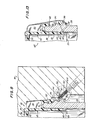
- FIG. 14 illustrates the position of the cork unit of the present invention after the retention means has been removed and the sleeve 48 pulled out of the neck of the bottle.
- the two sets of tethers will be partially straightened out to permit the ends of the tethers attached to the disk 76 to be pulled away from the mouth of the bottle.
- the energy-absorbing links will be tensioned. If the tensioning is sufficiently great, as may or may not be the case, the links will break as indicated in FIG. 14.
- the force tending to propel the stopper will be at least partially absorbed by the energy-absorbing links.
- the sleeve can be displaced to one side as shown in FIG. 14 where the formerly lower end of the stopper rests against the side of the bottle below the lowermost flange on the neck out of the way of the stream of fluid issuing from the mouth of the bottle. There is usually no tendency with the construction described thus far for the removed stopper, even though still attached to the ring, to interfere with outflow of liquid from the bottle.
- FIGs. 15 through 17 show a bottle and stopper unit which are essentially identical to those shown in the preceding FIGs. except that only one set of tethers is employed.
- a frangible bridge 110 is supplied which is diametrically opposed to this set of tethers and ruptures when the ring is depressed at the station 26.
- the tethers are asymetric and there is even less tendency for the removed sleeve to interfere with the outflowing stream of liquid from the bottle.
Landscapes
- Engineering & Computer Science (AREA)
- Mechanical Engineering (AREA)
- Closures For Containers (AREA)
Applications Claiming Priority (2)
| Application Number | Priority Date | Filing Date | Title |
|---|---|---|---|
| US576611 | 1984-02-03 | ||
| US06/576,611 US4513870A (en) | 1981-01-09 | 1984-02-03 | Bottle with a one-piece corking means |
Publications (2)
| Publication Number | Publication Date |
|---|---|
| EP0152171A2 true EP0152171A2 (de) | 1985-08-21 |
| EP0152171A3 EP0152171A3 (de) | 1986-08-20 |
Family
ID=24305172
Family Applications (1)
| Application Number | Title | Priority Date | Filing Date |
|---|---|---|---|
| EP85300165A Ceased EP0152171A3 (de) | 1984-02-03 | 1985-01-10 | Flasche und deren Stopfen |
Country Status (4)
| Country | Link |
|---|---|
| US (1) | US4513870A (de) |
| EP (1) | EP0152171A3 (de) |
| ES (1) | ES292842Y (de) |
| PT (1) | PT79915B (de) |
Cited By (2)
| Publication number | Priority date | Publication date | Assignee | Title |
|---|---|---|---|---|
| GB2231864A (en) * | 1988-05-16 | 1990-11-28 | Hatz Motoren | Safety device for preventing the loss of container closure plugs |
| GB2426507A (en) * | 2005-05-25 | 2006-11-29 | Mark Lee | Closure for bottles containing effervescent liquids |
Families Citing this family (18)
| Publication number | Priority date | Publication date | Assignee | Title |
|---|---|---|---|---|
| US4546893A (en) * | 1984-10-22 | 1985-10-15 | Gene Stull | Tamper-evident closure cap construction |
| GB8615169D0 (en) * | 1986-06-20 | 1986-07-23 | Lingner & Fischer Gmbh | Container |
| US5816428A (en) * | 1994-09-28 | 1998-10-06 | The Coca-Cola Company | Easy-open can end and spout |
| US5685444A (en) * | 1995-09-19 | 1997-11-11 | Valley; Joseph P. | Tamper-evident hinged closure cap construction |
| US20050199631A1 (en) * | 2003-02-25 | 2005-09-15 | Raymond Alois | Beverage tap spout plug |
| US7318656B1 (en) * | 2005-08-11 | 2008-01-15 | Frantz Merine | Illuminating bottle closure |
| ITMS20070003A1 (it) * | 2007-02-01 | 2008-08-02 | Dante Bertelloni | Dispositivo di ritenzione del tappo per bottiglie di spumante o altri liquidi gassati con espulsione controllata di sicurezza |
| US20080197135A1 (en) * | 2007-02-20 | 2008-08-21 | Berman Ronald H | Beverage spout with safety tether |
| US8439212B2 (en) * | 2009-11-02 | 2013-05-14 | Berry Plastics Corporation | Tamper-evident container closure with flip-top cap |
| US20150375901A1 (en) * | 2014-06-30 | 2015-12-31 | Karen J. Orlich | Reusable, eco-friendly container for storing and dispensing food and beverage |
| MX2020011242A (es) * | 2018-04-26 | 2021-01-20 | Obrist Closures Switzerland | Cierre. |
| CN116062306B (zh) | 2019-05-13 | 2025-03-14 | 赫斯基注塑系统有限公司 | 用于容器的封闭装置及用于形成封闭装置的模具 |
| EP3741703B1 (de) * | 2019-05-21 | 2022-03-02 | Société Lorraine de Capsules Metalliques - Manufacture de Bouchage | Schraubverschluss, der nach seiner öffnung am behälter fixiert bleibt |
| USD1013512S1 (en) | 2019-10-10 | 2024-02-06 | Merrilee Kick | Container |
| WO2021068058A1 (en) | 2019-10-11 | 2021-04-15 | Husky Injection Molding Systems Ltd. | Closure device for container |
| US11975889B2 (en) | 2021-09-02 | 2024-05-07 | Merrilee Kick | Container apparatus |
| IT202100029978A1 (it) * | 2021-11-26 | 2023-05-26 | Guala Pack Spa | Chiusura per una cannuccia di un imballo flessibile a pareti sottili |
| IT202300019383A1 (it) * | 2023-09-21 | 2025-03-21 | Marco Moroni Sagl | Sistema di sicurezza per l’espulsione di tappi di bottiglia |
Family Cites Families (6)
| Publication number | Priority date | Publication date | Assignee | Title |
|---|---|---|---|---|
| DE2200857A1 (de) * | 1972-01-08 | 1973-07-12 | Peter Schreibelmayer | Druckbehaelter |
| FR2329536A1 (fr) * | 1973-07-02 | 1977-05-27 | Somepla Sa | Nouvelle capsule a vis inviolable et imperdable |
| US3994409A (en) * | 1975-06-06 | 1976-11-30 | Nightengale Jr Richard C | Easy opening closure |
| US4054221A (en) * | 1976-06-22 | 1977-10-18 | Glover Ellis C | Bottle closure |
| CA1170214A (en) * | 1981-01-09 | 1984-07-03 | Efim Zaltsman | Method and apparatus for stoppering modified bottles with a one-piece corking means |
| US4474302A (en) * | 1983-11-03 | 1984-10-02 | James R. Goldberg | Safety champagne cork |
-
1984
- 1984-02-03 US US06/576,611 patent/US4513870A/en not_active Expired - Fee Related
-
1985
- 1985-01-10 EP EP85300165A patent/EP0152171A3/de not_active Ceased
- 1985-02-01 PT PT79915A patent/PT79915B/pt unknown
- 1985-02-01 ES ES1985292842U patent/ES292842Y/es not_active Expired
Cited By (5)
| Publication number | Priority date | Publication date | Assignee | Title |
|---|---|---|---|---|
| GB2231864A (en) * | 1988-05-16 | 1990-11-28 | Hatz Motoren | Safety device for preventing the loss of container closure plugs |
| US5031589A (en) * | 1988-05-16 | 1991-07-16 | Motorenfabrik Hatz Gmbh & Co. Kg | Safety device for preventing the loss of container closure plugs |
| GB2231864B (en) * | 1988-05-16 | 1993-10-20 | Hatz Motoren | Metering device |
| GB2426507A (en) * | 2005-05-25 | 2006-11-29 | Mark Lee | Closure for bottles containing effervescent liquids |
| GB2426507B (en) * | 2005-05-25 | 2009-01-28 | Mark Lee | Improvements in or relating to bottle closures |
Also Published As
| Publication number | Publication date |
|---|---|
| PT79915A (en) | 1985-03-01 |
| US4513870A (en) | 1985-04-30 |
| PT79915B (en) | 1986-09-11 |
| ES292842Y (es) | 1987-10-16 |
| EP0152171A3 (de) | 1986-08-20 |
| ES292842U (es) | 1987-03-16 |
Similar Documents
| Publication | Publication Date | Title |
|---|---|---|
| US4513870A (en) | Bottle with a one-piece corking means | |
| US5732838A (en) | Plastic blow molded container having lower annular grip | |
| US4474302A (en) | Safety champagne cork | |
| US4583652A (en) | Safety closure device | |
| US4564114A (en) | Molded safety closure device | |
| US4442735A (en) | Champagne cork puller | |
| KR970010905B1 (ko) | 취입식 플라스틱 용기 | |
| US4573602A (en) | Molded safety closure device and method for making same | |
| US4541795A (en) | Injection mold for a bottle closure device | |
| US4598613A (en) | Champagne bottle opener | |
| US3028992A (en) | Reusable tamper-indicating container closure | |
| JP2019048658A (ja) | 炭酸ガス含有発泡性飲料の封止栓および包装体 | |
| US4569440A (en) | Carrier for bottles and the like | |
| JPH10500090A (ja) | ワインボトル用コルク栓 | |
| EP4003030A1 (de) | Gewölbter behälter mit stickstoffschacht und verschlussmechanismus | |
| US5069345A (en) | Plastic container with tear opening feature | |
| WO1995004689A1 (en) | Beverage container | |
| US5806699A (en) | Closure vent arrangement and forming method therefor | |
| US5967351A (en) | Tamper-indicating closure with tapered connectors | |
| US3620412A (en) | Package for resilient elements or those stored under spring pressure | |
| US4650083A (en) | Safety closure for use in conjunction with bottling of champagne and other sparkling wines | |
| US4429799A (en) | Bottle with a one-piece corking means | |
| US20170361998A1 (en) | Non-metal and hybrid bottle crowns with opener assembly | |
| US5405033A (en) | Safety device for corks | |
| JP2018095291A (ja) | 開栓具付きキャップ |
Legal Events
| Date | Code | Title | Description |
|---|---|---|---|
| PUAI | Public reference made under article 153(3) epc to a published international application that has entered the european phase |
Free format text: ORIGINAL CODE: 0009012 |
|
| AK | Designated contracting states |
Designated state(s): DE FR GB IT |
|
| PUAL | Search report despatched |
Free format text: ORIGINAL CODE: 0009013 |
|
| AK | Designated contracting states |
Kind code of ref document: A3 Designated state(s): DE FR GB IT |
|
| 17P | Request for examination filed |
Effective date: 19870216 |
|
| 17Q | First examination report despatched |
Effective date: 19880425 |
|
| STAA | Information on the status of an ep patent application or granted ep patent |
Free format text: STATUS: THE APPLICATION HAS BEEN REFUSED |
|
| 18R | Application refused |
Effective date: 19890519 |
|
| RIN1 | Information on inventor provided before grant (corrected) |
Inventor name: ZALTSMAN, EFIM |