EP0152186A2 - Corrélateur optique - Google Patents
Corrélateur optique Download PDFInfo
- Publication number
- EP0152186A2 EP0152186A2 EP85300308A EP85300308A EP0152186A2 EP 0152186 A2 EP0152186 A2 EP 0152186A2 EP 85300308 A EP85300308 A EP 85300308A EP 85300308 A EP85300308 A EP 85300308A EP 0152186 A2 EP0152186 A2 EP 0152186A2
- Authority
- EP
- European Patent Office
- Prior art keywords
- correlator
- spatial light
- lens
- transducer
- hologram recorder
- Prior art date
- Legal status (The legal status is an assumption and is not a legal conclusion. Google has not performed a legal analysis and makes no representation as to the accuracy of the status listed.)
- Withdrawn
Links
Images

Classifications
-
- G—PHYSICS
- G06—COMPUTING OR CALCULATING; COUNTING
- G06E—OPTICAL COMPUTING DEVICES
- G06E3/00—Devices not provided for in group G06E1/00, e.g. for processing analogue or hybrid data
- G06E3/001—Analogue devices in which mathematical operations are carried out with the aid of optical or electro-optical elements
- G06E3/005—Analogue devices in which mathematical operations are carried out with the aid of optical or electro-optical elements using electro-optical or opto-electronic means
Definitions
- This invention relates to optical correlators, and in particular to optical correlation using a Joint Transform Correlator.
- a Joint Transform Correlator light from a first spatial light modulator, which creates a coherent light phase or contrast image, is collected by a first lens or lens system and is interferred in the Fourier transform plane with light collected by that lens or lens system from a second spatial light modulator located alongside the first.
- a hologram recording device is located at this Fourier transform plane, and this, in its turn, is illuminated with coherent light which is collected by a second lens or lens system to form a correlation image on a two-dimensional image receiving photo-electronic transducer in the Fourier transform plane of this second lens or lens system.
- the transducer is typically provided by a photodetector array, but at least in principle could alternatively be provided by a single large area detector whose surface is scanned to extract the image information after the manner employed in certain types of video camera.
- a Joint Transform Correlator reference may be made to the article by D. Casasent, entitled “Optical Computing Techniques for Radar and Sonar Signal Processing", appearing in the Proceedings of the Society of Photo-Instrumentation Engineers Vol.118 (1977), 100.
- optical correlators One of the applications of optical correlators is to determine whether a particular object, hereinafter referred to as the quarry, is present in a particular scene under investigation which will generally contain other extraneous objects and/or clutter noise. If the quarry is present in the investigation scene, the correlator will normally be required to identify its location in that scene. These functions of identification and location are performed by correlating the investigation scene with a reference scene that contains a reference object or archetype of the quarry.
- Optical correlators perform well when there is a perfect match between quarry amongst its background 'clutter' in the investigation scene and the archetype in the reference scene.
- a Joint Transform Correlator the position of the quarry can be ascertained from the position of the correlation peak in the output plane at which is situated the two-dimensional transducer.
- small deviations from a perfect match between quarry and archetype, such as orientational misalignments and scale variations result in severe degradations of - the correlation peak.
- the present invention is concerned with a correlation system in which the deviations are reduced by means of a servo-feedback system which employs the correlation signal output to modify the display of the archetype in the reference scene so as to optimise the correlation peak.
- a joint transform correlator having first and second spatial light modulators for forming adjacent first and second coherent light phase or contrast images in the input or object plane of the correlator, a dynamic hologram recorder spaced from the object plane, and an intervening first lens or lens system located such that the dynamic hologram recorder lies in the Fourier transform plane of the coherent light images, a coherent light source for illuminating the dynamic hologram recorder, a two-dimensional image receiving photoelectronic transducer, and an intervening second lens or lens system located such that the transducer lies in the Fourier transform plane of the dynamic hologram recorder, wherein the second of the spatial light modulators is adapted to be electronically controlled using a servo-feedback system to change its image to maximise the sharpness of the correlation image formed on the transducer.
- the basic components of the Joint Transform Correlator of Figure 1 are a first coherent light source 10, first and second spatial light modulators 11 and 12 for displaying respectively the quarry scene and the reference scene, a first lens or lens system 13, a dynamic hologram recorder 14 for the temporary storage of a hologram in the Fourier transform plane, a second coherent light source 15, a second lens or lens system 16, a CCD photodiode array 17 in the detection or correlation plane, and a servo-feedback system 18 for controlling, with the output from the CCD array, the size and orientation of the archetype displayed by the second spatial light modulator 12.
- a laser Associated with the first coherent light source 10, a laser, is a beam expander 19 to broaden its output sufficiently to flood the two spatial light modulators 11 and 12. These devices are of reflex rather than transmission type, and hence the light from the laser 10 is directed on to the devices via a beam splitter 20. (If transmission type devices were employed the beam splitter would be omitted and the position of the laser appropriately changed.)
- a preferred form of spatial light modulator is a liquid crystal cell matrix addressed via an active silicon backing to the liquid crystal layer. Examples of such devices are deserted in our Patent Specification No. 2118347A.
- the dynamic hologram recorder may be a degenerate four-wave mixer, for instance of the bismuth silicon oxide type. It is not necessary however, for this function for the two waves involved in 'writing' to have the same frequency as the two used for 'reading', i.e. the emission wavelength of the second coherent light source 15, also a laser, is not necessarily the same as that of the first laser 10.
- the choice of different wavelengths enables the use of a thermal type four wave-mixer in which a thermal pattern is created by the absorption by the medium of the light of the writing wavelength, while a different wavelength, at which the medium is substantially transparent, is employed for reading so that the reading operation shall leave the thermal pattern substantially undisturbed.
- a thermal type four wave-mixer in which a thermal pattern is created by the absorption by the medium of the light of the writing wavelength, while a different wavelength, at which the medium is substantially transparent, is employed for reading so that the reading operation shall leave the thermal pattern substantially undisturbed.
- One class of such thermal four-wave mixers is provided by the class of liquid crystal cell described in patent application No. ........ claiming priority from UK Patent Application No. 8403228 and identified as W.A. Crossland - P.W. Ross - N. Collings 45-13-2.
- the second laser is, like the first laser, provided with a beam expander 21 and beam splitter 22.
- the CCD photodiode array is mounted in the Fourier transform plane of the dynamic hologram recorder formed by the second lens or lens system 16. Associated with this array is support electronic hardware in the servo-feedback system 18 this hardware consisting of an A/D converter, an image memory, and a microprocessor or minicomputer.
- the position of the correlation spot formed on the array 17 provides information on the location of the quarry in the scene under investigation.
- the size of the array 17 is smaller than the joint size of the two spatial light modulators 11 and 12, and therefore some demagnification is required in the system. This is acheived by making the focal length f 1 of lens 13 larger than the corresponding focal length f 2 of lens 16. This provides a demagnification factor of f 2 /f l .
- the essence of the correlator is that, under the control of the servo-feedback system 18, the presentation . of the archetype in the reference field as displayed by spatial light modulator 12 is modified to provide an optimised correlation peak at the array 17.
- the servo-feedback system may be programmed to achieve the optimisation.
- One route is for the servo-feedback system to arrange for the displayed representation of the archetype to be first progressively rotated to find the optimum orientation, and then for magnitude to be progressively changed to find the optimum match of size.
- the amplitude of the correlation peak falls quite rapidly with mismatch of both size and orientation. Thus typically it may be reduced by 3dB for a misalignment of 0.2 0 or a scale mismatch of 0.5%.
- a problem in all correlator systems is the low tolerance of the system with respect to optical imperfections of the spatial light modulators that give rise to systematic error/noise, which is the result of distortion the optical wavefronts transmitted or reflected by such devices.
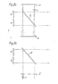
- This can be compensated by means of a holographic correction element 24, used as indicated in Figures 2a and 2b which depict a part of the correlator of Figure 1 modified to include such an element.
- This arrangement is suited to the operation of the spatial light modulators 11 and 12 as phase image generating devices i.e. the spatial field information is impressed on the phase of the interrogating beam of light from the laser 10 rather than upon its amplitude.
- Figure 2a depicts the arrangement employed to create the required pattern of the correction element 24.
- a collimated beam of light from the laser 10 (not shown in this Figure) is incident normally upon the spatial light modulators 11 and 12 after transmission through the beam splitter 20.
- the laser 10 and its beam expander 19 is required to be temporarily shifted from the position shown in Figure 1 to the position occupied in that Figure by the lens 13.
- Light which is reflected by the spatial light modulators 11 and 12, and is reflected by the beam splitter 20 is incident normally upon the undeveloped correction element 24.
- it is arranged to interfere with light from the laser that was first reflected by the beam splitter 20, and was then reflected by a plane mirror 25 before being transmitted through the beam splitter 20.
- the plane mirror 25 is tilted at a small angle 'a' so that the two beams interfere.
- the resulting interference pattern is recorded in the correction element 24 while no data is applied to either spatial light modulator 11 or 12.
- the reflectivity of the mirror should match that of the spatial light modulators.
- bleached silver-based photographic emulsions have been found to provide a diffraction efficiency which is surpassed by other types of photosensitive emulsions, such as the dichromated gelatin emulsion, and hence it may be preferred to use one of these non-silver-based emulsions where such use is not precluded by virtue of wavelength sensitivity considerations.
Landscapes
- Physics & Mathematics (AREA)
- Engineering & Computer Science (AREA)
- Theoretical Computer Science (AREA)
- Mathematical Physics (AREA)
- Nonlinear Science (AREA)
- Optics & Photonics (AREA)
- General Physics & Mathematics (AREA)
- Holo Graphy (AREA)
- Gyroscopes (AREA)
Applications Claiming Priority (2)
| Application Number | Priority Date | Filing Date | Title |
|---|---|---|---|
| GB08403227A GB2154092A (en) | 1984-02-07 | 1984-02-07 | Optical correlator |
| GB8403227 | 1984-02-07 |
Publications (2)
| Publication Number | Publication Date |
|---|---|
| EP0152186A2 true EP0152186A2 (fr) | 1985-08-21 |
| EP0152186A3 EP0152186A3 (fr) | 1987-08-26 |
Family
ID=10556226
Family Applications (1)
| Application Number | Title | Priority Date | Filing Date |
|---|---|---|---|
| EP85300308A Withdrawn EP0152186A3 (fr) | 1984-02-07 | 1985-01-17 | Corrélateur optique |
Country Status (3)
| Country | Link |
|---|---|
| EP (1) | EP0152186A3 (fr) |
| JP (1) | JPS60181877A (fr) |
| GB (1) | GB2154092A (fr) |
Cited By (6)
| Publication number | Priority date | Publication date | Assignee | Title |
|---|---|---|---|---|
| FR2588675A1 (fr) * | 1985-10-16 | 1987-04-17 | Thomson Csf | Systeme de traitement optique d'images lumineuses |
| EP0182509A3 (en) * | 1984-11-14 | 1988-04-27 | Stc Plc | Two-dimensional optical information processing apparatus |
| AU616640B2 (en) * | 1986-10-17 | 1991-11-07 | Global Holonetics Corporation | Transform optical processing system |
| EP0403305A3 (fr) * | 1989-06-16 | 1992-11-19 | Seiko Instruments Inc. | Appareil optique pour la reconnaissance de formes |
| DE10085411B3 (de) * | 2000-01-19 | 2017-03-02 | Hamamatsu Photonics K.K. | Laserlichtbearbeitungsvorrichtung mit einem räumlichen Lichtmodulator |
| CN112925184A (zh) * | 2021-01-29 | 2021-06-08 | 昆明理工大学 | 基于双声光调制器的全息图像重建方法及重建系统 |
Families Citing this family (2)
| Publication number | Priority date | Publication date | Assignee | Title |
|---|---|---|---|---|
| GB9117463D0 (en) * | 1991-08-13 | 1991-09-25 | Secr Defence | A broadband optical target detector |
| CN114503000B (zh) * | 2019-10-02 | 2024-10-18 | 科格尼菲博有限公司 | 光学神经元单元及其网络 |
Family Cites Families (3)
| Publication number | Priority date | Publication date | Assignee | Title |
|---|---|---|---|---|
| US3747103A (en) * | 1963-04-22 | 1973-07-17 | Singer Co | Cross correlator with automatic rotational alignment |
| FR2499735A1 (fr) * | 1981-02-06 | 1982-08-13 | Thomson Csf | Dispositif optique transformateur de fourier et correlateur optique mettant en oeuvre ce dispositif optique transformateur de fourier |
| JPS57138616A (en) * | 1981-02-20 | 1982-08-27 | Mitsubishi Electric Corp | Optical correlation processing device |
-
1984
- 1984-02-07 GB GB08403227A patent/GB2154092A/en not_active Withdrawn
-
1985
- 1985-01-17 EP EP85300308A patent/EP0152186A3/fr not_active Withdrawn
- 1985-02-06 JP JP2158785A patent/JPS60181877A/ja active Pending
Cited By (9)
| Publication number | Priority date | Publication date | Assignee | Title |
|---|---|---|---|---|
| EP0182509A3 (en) * | 1984-11-14 | 1988-04-27 | Stc Plc | Two-dimensional optical information processing apparatus |
| FR2588675A1 (fr) * | 1985-10-16 | 1987-04-17 | Thomson Csf | Systeme de traitement optique d'images lumineuses |
| EP0225205A1 (fr) * | 1985-10-16 | 1987-06-10 | Thomson-Csf | Système de traitement optique d'images lumineuses |
| AU616640B2 (en) * | 1986-10-17 | 1991-11-07 | Global Holonetics Corporation | Transform optical processing system |
| EP0403305A3 (fr) * | 1989-06-16 | 1992-11-19 | Seiko Instruments Inc. | Appareil optique pour la reconnaissance de formes |
| US5309523A (en) * | 1989-06-16 | 1994-05-03 | Seiko Instruments Inc. | Optical pattern recognition apparatus |
| DE10085411B3 (de) * | 2000-01-19 | 2017-03-02 | Hamamatsu Photonics K.K. | Laserlichtbearbeitungsvorrichtung mit einem räumlichen Lichtmodulator |
| CN112925184A (zh) * | 2021-01-29 | 2021-06-08 | 昆明理工大学 | 基于双声光调制器的全息图像重建方法及重建系统 |
| CN112925184B (zh) * | 2021-01-29 | 2022-07-12 | 昆明理工大学 | 基于双声光调制器的全息图像重建方法及重建系统 |
Also Published As
| Publication number | Publication date |
|---|---|
| EP0152186A3 (fr) | 1987-08-26 |
| JPS60181877A (ja) | 1985-09-17 |
| GB2154092A (en) | 1985-08-29 |
Similar Documents
| Publication | Publication Date | Title |
|---|---|---|
| US4442455A (en) | Optical system for observation in real time with scanning | |
| US5227859A (en) | Passive coherent radiation detection system | |
| US4139257A (en) | Synchronizing signal generator | |
| JP2527807B2 (ja) | 光学的連想識別装置 | |
| US4084255A (en) | Positional, rotational and scale invariant optical correlation method and apparatus | |
| US4772101A (en) | Remotely controllable real-time optical processor | |
| US4275454A (en) | Optical system phase error compensator | |
| US4277137A (en) | Coherent optical correlator | |
| JPH06194709A (ja) | リアルタイム光学的相関装置 | |
| CA1291657C (fr) | Systemes et methodes de traitement pour memoires de correlateurs optiques | |
| US4383734A (en) | Real-time optical correlation system | |
| US3795768A (en) | Holographic image scanner/recorder system | |
| US3632182A (en) | Method and apparatus for interference pattern recording | |
| EP0152186A2 (fr) | Corrélateur optique | |
| JPS60182412A (ja) | コヒーレント光の光学的プロセツサ | |
| US4514038A (en) | Optical Fourier transformer device and optical correlator incorporating the said device | |
| US4403352A (en) | Switching device for optical beams and telephone exchange incorporating such a device | |
| US3831135A (en) | Optical imaging of sound fields by heterodyning | |
| CN116841172B (zh) | 一种基于光学扫描全息的全息打印系统及方法 | |
| JP2744494B2 (ja) | スペックル利用測定装置 | |
| US3792422A (en) | Cameras for acoustic holography | |
| Harris et al. | Stroboscopic interferometer | |
| US11892802B2 (en) | Lensless holographic imaging system using holographic optical element | |
| US3539242A (en) | On-axis holography | |
| US4118685A (en) | Holographic signature processor |
Legal Events
| Date | Code | Title | Description |
|---|---|---|---|
| PUAI | Public reference made under article 153(3) epc to a published international application that has entered the european phase |
Free format text: ORIGINAL CODE: 0009012 |
|
| AK | Designated contracting states |
Designated state(s): AT BE CH DE FR IT LI LU NL SE |
|
| RAP1 | Party data changed (applicant data changed or rights of an application transferred) |
Owner name: STC PLC |
|
| RAP1 | Party data changed (applicant data changed or rights of an application transferred) |
Owner name: STC PLC |
|
| PUAL | Search report despatched |
Free format text: ORIGINAL CODE: 0009013 |
|
| AK | Designated contracting states |
Kind code of ref document: A3 Designated state(s): AT BE CH DE FR IT LI LU NL SE |
|
| STAA | Information on the status of an ep patent application or granted ep patent |
Free format text: STATUS: THE APPLICATION IS DEEMED TO BE WITHDRAWN |
|
| 18D | Application deemed to be withdrawn |
Effective date: 19870804 |
|
| RIN1 | Information on inventor provided before grant (corrected) |
Inventor name: COLLINGS, NEIL |