EP0152260A2 - Aufhängevorrichtung für das Antriebsrad eines motorangetriebenen Fahrzeugs - Google Patents
Aufhängevorrichtung für das Antriebsrad eines motorangetriebenen Fahrzeugs Download PDFInfo
- Publication number
- EP0152260A2 EP0152260A2 EP85300750A EP85300750A EP0152260A2 EP 0152260 A2 EP0152260 A2 EP 0152260A2 EP 85300750 A EP85300750 A EP 85300750A EP 85300750 A EP85300750 A EP 85300750A EP 0152260 A2 EP0152260 A2 EP 0152260A2
- Authority
- EP
- European Patent Office
- Prior art keywords
- swing arm
- link
- drive wheel
- wheel
- levers
- Prior art date
- Legal status (The legal status is an assumption and is not a legal conclusion. Google has not performed a legal analysis and makes no representation as to the accuracy of the status listed.)
- Granted
Links
Images

Classifications
-
- B—PERFORMING OPERATIONS; TRANSPORTING
- B62—LAND VEHICLES FOR TRAVELLING OTHERWISE THAN ON RAILS
- B62K—CYCLES; CYCLE FRAMES; CYCLE STEERING DEVICES; RIDER-OPERATED TERMINAL CONTROLS SPECIALLY ADAPTED FOR CYCLES; CYCLE AXLE SUSPENSIONS; CYCLE SIDECARS, FORECARS, OR THE LIKE
- B62K25/00—Axle suspensions
- B62K25/04—Axle suspensions for mounting axles resiliently on cycle frame or fork
- B62K25/12—Axle suspensions for mounting axles resiliently on cycle frame or fork with rocking arm pivoted on each fork leg
- B62K25/22—Axle suspensions for mounting axles resiliently on cycle frame or fork with rocking arm pivoted on each fork leg with more than one arm on each fork leg
- B62K25/26—Axle suspensions for mounting axles resiliently on cycle frame or fork with rocking arm pivoted on each fork leg with more than one arm on each fork leg for rear wheel
-
- F—MECHANICAL ENGINEERING; LIGHTING; HEATING; WEAPONS; BLASTING
- F02—COMBUSTION ENGINES; HOT-GAS OR COMBUSTION-PRODUCT ENGINE PLANTS
- F02B—INTERNAL-COMBUSTION PISTON ENGINES; COMBUSTION ENGINES IN GENERAL
- F02B29/00—Engines characterised by provision for charging or scavenging not provided for in groups F02B25/00, F02B27/00 or F02B33/00 - F02B39/00; Details thereof
- F02B29/04—Cooling of air intake supply
- F02B29/0406—Layout of the intake air cooling or coolant circuit
- F02B29/0418—Layout of the intake air cooling or coolant circuit the intake air cooler having a bypass or multiple flow paths within the heat exchanger to vary the effective heat transfer surface
-
- F—MECHANICAL ENGINEERING; LIGHTING; HEATING; WEAPONS; BLASTING
- F02—COMBUSTION ENGINES; HOT-GAS OR COMBUSTION-PRODUCT ENGINE PLANTS
- F02B—INTERNAL-COMBUSTION PISTON ENGINES; COMBUSTION ENGINES IN GENERAL
- F02B61/00—Adaptations of engines for driving vehicles or for driving propellers; Combinations of engines with gearing
- F02B61/02—Adaptations of engines for driving vehicles or for driving propellers; Combinations of engines with gearing for driving cycles
-
- Y—GENERAL TAGGING OF NEW TECHNOLOGICAL DEVELOPMENTS; GENERAL TAGGING OF CROSS-SECTIONAL TECHNOLOGIES SPANNING OVER SEVERAL SECTIONS OF THE IPC; TECHNICAL SUBJECTS COVERED BY FORMER USPC CROSS-REFERENCE ART COLLECTIONS [XRACs] AND DIGESTS
- Y02—TECHNOLOGIES OR APPLICATIONS FOR MITIGATION OR ADAPTATION AGAINST CLIMATE CHANGE
- Y02T—CLIMATE CHANGE MITIGATION TECHNOLOGIES RELATED TO TRANSPORTATION
- Y02T10/00—Road transport of goods or passengers
- Y02T10/10—Internal combustion engine [ICE] based vehicles
- Y02T10/12—Improving ICE efficiencies
Definitions
- This invention relates to a drive wheel suspension system for motor-driven vehicles of the kind in which a drive wheel is driven by a chain cooperating with sprockets provided on the motor or engine shaft and on the wheel shaft.
- motorcycles are typical of such.motor-driven vehicles and the invention is described as applied to a motorcycle.
- a swing arm for mounting the drive wheel, the swing arm having a pivot usually located in the region between the engine sprocket and the periphery of the driven wheel.
- Such an arrangement greatly reduces the overall weight of the parts and also reduces the inertia of the parts moving with the wheel and, consequently, improves the responsiveness of the wheel under various operating conditions including, for example, travel over rough terrain such as is commonly encountered in motocross racing.
- Such an arrangement also provides for use of a swing arm structure lying substantially in a plane containing the axes of the driving and driven sprockets, and this reduces certain of the undesirable forces which tend to occur especially during acceleration.
- the present invention contemplates use of an arrangement generally conforming with that of the prior patent 4,408,674 above referred to, but further provides certain suspension linkage elements positioned in a novel manner with respect to other linkage elements, thereby providing for further reduction of the forces which tend to induce "squat" when acceleration occurs.
- the motorcycle illustrated in the drawings is typical of motorcycles employed for motocross racing; and while the invention is applicable to vehicles of a variety of types, the arrangement of the invention is particularly desirable for motorcycles, and especially for motorcycles used for motocross racing.
- the invention is, therefore, illustrated and described in relation to such specific use.
- the motorcycle includes main frame components some of which are indicated at 9, 10, 11 and 12.
- the framing provides for support of an engine as indicated at 13, a rider's seat 14 and a fuel tank 15.
- the front wheel (not shown) is located to the left of the figure and the rear wheel is shown at 17, these wheels being mounted on the frame structure, only portions of which are shown.
- the suspension system for the rear or driving wheel 17 includes a swing arm 22 of a type commonly employed on motorcycles and comprising a forked structure embracing the rear wheel 17, as will be understood from Figure 2.
- the swing arm has heretofore been pivotally mounted at some point on the frame structure, usually to the rear of the engine; but in the arrangement illustrated, the swing arm is mounted in the manner fully described hereinafter.
- the drive system for the rear wheel 17 includes a sprocket 23 mounted on the engine shaft and a sprocket 24 mounted on the wheel 17, with a drive chain 25 engaging the engine and wheel sprockets, as clearly appears in the drawings.
- the motion of the swing arm 22 occur about an axis close to or coincident with the center 26 of the engine sprocket 23.
- the direct pivotal mounting of the swing arm 22 on the shaft or axis 26 is not practical because of interference with other parts and the undesired complexity of having the swing arm connected with the engine drive shaft, thereby interfering'with separate mounting and removal of the engine and of other parts.
- the arrangement of the invention utilizes a suspension system which achieves the objective of providing for pivotal motion of the swing arm 22 about or substantially about the axis of the engine or drive sprocket shaft 26; but this is accomplished without the complexity of direct pivotal mounting of the swing arm on the axis 26.
- a suspension linkage system is provided having an effective pivotal axis for the swing arm which is either coincident with or close to the axis of the sprocket 23, which latter is also customarily coincident with the engine shaft.
- the commonly used chain slack take-up device may be eliminated.
- the linkage arrangement herein disclosed achieves reduction in undesirable forces, even where the swing arm motion is not precisely coincident with the axis of the driving sprocket, as brought out more fully hereinafter.
- the structure provided includes a pair of levers 27 and 28 which are pivotally mounted on axes 29 and 30, carried by mounting brackets secured to the motorcycle framing, one offset above and the other offset below the sprocket shaft 26. These two levers lie in vertical planes laterally offset from each other and extend in a direction toward the drive wheel 17.
- the free ends of these levers are interconnected by a linkage system including a shaft 31, having at one end, an upwardly extended link arm 32, and at the other end, a downwardly extended link arm 33.
- the arms 32 and 33 and the shaft 31 thus form a generally upright link interconnecting the levers 27 and 28.
- the swing arm 22 is mounted on the shaft 31; and the lower pivoted arm 28 has an extension 28a with which a link 34a is pivoted, the link 34a being extended upwardly for pivotal attachment to the swing arm 22 at the pivot point 35a.
- the swing arm link 34a is positioned at an oblique angle to the swing arm for reasons more fully brought out hereinafter.
- a shock absorber mechanism preferably including both a spring and hydraulic damper, be arranged to react on the linkage, such as above described, rather than at an outboard point on the swing arm itself.
- the mechanism for yieldably resisting upward deflection of the drive wheel includes a shock absorber mechanism comprising a spring and hydraulic damper unit generally indicated at 36, this unit or assembly being compressible between end abutment elements reacting between the arm extension 28a and the arm 39 of a bellcrank pivoted on the frame of the motorcycle at 40 and having another arm 41 pivotally connected by means of link 42 with the pivot axis interconnecting the linkage parts 27 and 32.
- the arrangement of the linkage for the swing arm and for the shock resisting mechanism not only minimizes the inertia effects of these parts in relation to the motion or deflection of the driving wheel, but still further, the disposition of these various parts is important from the standpoint of concentrating those parts close to the center of gravity of the motorcycle as a whole.
- the geometry of the parts as described has special advantages in minimizing tendency for the deflection resisting forces to induce or contribute to undesirable motions of the motorcycle about its overall center of gravity.
- the disclosed arrangement is characterized by the fact that the driving wheel is, in effect, more isolated from the remainder of the motorcycle, particularly with regard to the motions of the drive wheel and the dynamic and inertia forces involved in such motions and also in the action of the shock absorber or other motion-resisting mechanism.
- the linkage parts involved in the arrangement disclosed may be accommodated in a smaller lateral or transverse space than is the case with certain other suspension mechanisms of the prior art. Because of this, notwithstanding the fact that the linkage provides a parallelogram effect causing the motion of the drive wheel to occur about the axis of the driving sprocket, the relatively small overall lateral dimension of the parts provides ground clearance at the two sides of the motorcycle even when making sharp turns, which ground clearance is greater than in many prior suspension arrangements. Because of this increased lateral ground clearance, various parts, especially the suspension parts, may be mounted in lower positions, with consequent lowering of the overall center of gravity of the motorcycle; and this is of advantage for reasons well understood in this art.
- the swing arm link 34a is obliquely inclined, having a pivotal connection 35a with the swing arm 22 and extending downwardly at an inwardly inclined angle with its lower end pivoted to a portion of the suspension linkage.
- the swing arm link 34a is pivotally connected at its lower end with the outward extension 28a of the lower arm or lever 28 of the inboard portion of the linkage, and it will be seen that the swing arm link 34a is extended from the swing arm in a direction forming an oblique angle 8 (see Figure 1) with respect to the generally upright link 32 - 33 of the inboard linkage parts. Specifically, the swing arm link 34a is extended in a direction forming an acute angle with respect to the generally upright link 32 - 33 of the inboard suspension coupling mechanism.
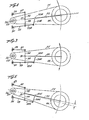
- Figures 3, 4 and 5 diagramatically illustrate the geometric interrelationship of the major components of the system structurally shown in Figures 1 and 2, Figure 3 showing the parts in the mid or partially deflected position of the suspension.
- Figure 4 shows the relationship of the parts at the maximum upwardly deflected position; and
- Figure 5 shows the relationship of the parts at the lowermost wheel position.
- the angle ⁇ of the link 34a relative to the general plane of the linkage parts 32 - 33 should be at least 10° in the middle setting of its pivotal range and may be up to about 75°. Values of 9 lying between about 15° and about 50° for the middle setting of its pivotal range are effective in many cases.
- the angle of ⁇ illustrated in Figure 1 is around 15° and in Figures 3, 4 and 5 it is 16° in the middle setting of its pivotal range (Figure 3), 14° in the Figure 4 setting and 181 ⁇ 2° in the Figure 5 setting.
Landscapes
- Engineering & Computer Science (AREA)
- Mechanical Engineering (AREA)
- Chemical & Material Sciences (AREA)
- Combustion & Propulsion (AREA)
- General Engineering & Computer Science (AREA)
- Physics & Mathematics (AREA)
- Thermal Sciences (AREA)
- Axle Suspensions And Sidecars For Cycles (AREA)
- Arrangement Or Mounting Of Propulsion Units For Vehicles (AREA)
- Vehicle Body Suspensions (AREA)
- Control Of Vehicle Engines Or Engines For Specific Uses (AREA)
- Automatic Cycles, And Cycles In General (AREA)
Priority Applications (1)
| Application Number | Priority Date | Filing Date | Title |
|---|---|---|---|
| AT85300750T ATE37169T1 (de) | 1984-02-06 | 1985-02-05 | Aufhaengevorrichtung fuer das antriebsrad eines motorangetriebenen fahrzeugs. |
Applications Claiming Priority (2)
| Application Number | Priority Date | Filing Date | Title |
|---|---|---|---|
| US06/577,026 US4558761A (en) | 1981-06-01 | 1984-02-06 | Motorcycle drive wheel suspension system |
| US577026 | 1984-02-06 |
Publications (3)
| Publication Number | Publication Date |
|---|---|
| EP0152260A2 true EP0152260A2 (de) | 1985-08-21 |
| EP0152260A3 EP0152260A3 (en) | 1986-10-15 |
| EP0152260B1 EP0152260B1 (de) | 1988-09-14 |
Family
ID=24306981
Family Applications (1)
| Application Number | Title | Priority Date | Filing Date |
|---|---|---|---|
| EP85300750A Expired EP0152260B1 (de) | 1984-02-06 | 1985-02-05 | Aufhängevorrichtung für das Antriebsrad eines motorangetriebenen Fahrzeugs |
Country Status (5)
| Country | Link |
|---|---|
| US (1) | US4558761A (de) |
| EP (1) | EP0152260B1 (de) |
| AT (1) | ATE37169T1 (de) |
| AU (1) | AU586619B2 (de) |
| DE (1) | DE3564927D1 (de) |
Cited By (3)
| Publication number | Priority date | Publication date | Assignee | Title |
|---|---|---|---|---|
| WO1989006203A1 (en) * | 1988-01-07 | 1989-07-13 | Alfons Van De Vel | Wheel suspension for a wheel driven by an endless transmission |
| GR890100148A (en) * | 1989-03-08 | 1990-07-31 | Georgios Liapis | Arrangement for cars suspension |
| WO1996007582A1 (en) * | 1994-09-09 | 1996-03-14 | Rockshox, Inc. | Rear wheel suspension for a bicycle and bicycle equipped therewith |
Families Citing this family (17)
| Publication number | Priority date | Publication date | Assignee | Title |
|---|---|---|---|---|
| US4724920A (en) * | 1985-12-06 | 1988-02-16 | Honda Giken Kogyo Kabushiki Kaisha | Rear suspension systems for automatic two-wheeled vehicles |
| US4765432B1 (en) * | 1987-05-21 | 1997-09-16 | H Paul Odom | Motorcycle having a suspension coupled seat |
| US5829773A (en) * | 1996-01-19 | 1998-11-03 | Tenneco Automotive Inc. | Modular telescopic front fork assembly |
| CN101068709B (zh) | 2004-09-15 | 2011-06-08 | 耶蒂自行车有限责任公司 | 用于自行车的后悬挂系统 |
| US7661503B2 (en) * | 2005-04-07 | 2010-02-16 | Orion Dynamics, Inc. | Vehicle suspension system for stable squat magnitude responses |
| US7665568B2 (en) * | 2007-10-31 | 2010-02-23 | Harley-Davidson Motor Company Group, Inc. | Vehicle having multiple-piece pivot shaft assembly |
| US9821879B2 (en) | 2010-08-20 | 2017-11-21 | Yeti Cycling, Llc | Reciprocating rail movement suspension system |
| WO2012024697A1 (en) | 2010-08-20 | 2012-02-23 | Peter Zawistowski | Link suspension system |
| JP5611911B2 (ja) * | 2011-08-31 | 2014-10-22 | 本田技研工業株式会社 | 小型車両用スイングアーム |
| US8540045B2 (en) * | 2011-10-31 | 2013-09-24 | Tanom Motors, LLC | Systems and apparatus for a three-wheeled vehicle |
| US10766563B2 (en) | 2013-01-16 | 2020-09-08 | Yeti Cyclying, Llc | Rail suspension with integral shock and dampening mechanism |
| US12600431B2 (en) | 2017-03-17 | 2026-04-14 | Yeti Cycling, Llc | Vehicle suspension linkage |
| WO2018170505A1 (en) | 2017-03-17 | 2018-09-20 | Yeti Cycling, Llc | Vehicle suspension linkage |
| US10926830B2 (en) | 2017-07-07 | 2021-02-23 | Yeti Cycling, Llc | Vehicle suspension linkage |
| US12077241B2 (en) | 2019-02-01 | 2024-09-03 | Yeti Cycling, Llc | Multi-body vehicle suspension linkage |
| US12145684B2 (en) | 2019-12-24 | 2024-11-19 | Yeti Cycling, Llc | Constrained multiple instantaneous velocity center linkage assembly for vehicle suspension |
| US12384484B2 (en) | 2020-11-18 | 2025-08-12 | Yeti Cycling, Llc | Integrated motor mount and suspension pivot |
Family Cites Families (15)
| Publication number | Priority date | Publication date | Assignee | Title |
|---|---|---|---|---|
| US2705154A (en) * | 1950-04-18 | 1955-03-29 | Torre Pier Luigi | Spring suspension system for motorcycles |
| DE847109C (de) * | 1951-04-12 | 1952-08-21 | Ardie Werk Ag | Hinterradfederung fuer Zweiradfahrzeuge |
| US3819002A (en) * | 1972-08-29 | 1974-06-25 | Borg Warner | Drive system |
| US3917313A (en) * | 1973-12-17 | 1975-11-04 | Bultaco Compania Espanola Espa | Motorcycle suspension system |
| FR2306122A1 (fr) * | 1975-04-03 | 1976-10-29 | Doncque Pierre | Dispositif de suspension de bras oscillant de roue arriere de motocyclette |
| US4058181A (en) * | 1976-03-16 | 1977-11-15 | Buell Erik F | Motorcycle suspension systems |
| US4034821A (en) * | 1976-06-09 | 1977-07-12 | Stoddard Richard B | Motorcycle chain drive |
| US4114918A (en) * | 1977-03-18 | 1978-09-19 | Parlec, Inc. | Suspension system for wheel of a motor bike |
| US4265329A (en) * | 1978-02-24 | 1981-05-05 | Cortanze Andre | Frameless motorcycle |
| GB1600934A (en) * | 1978-05-19 | 1981-10-21 | Silk Eng Derby Ltd | Motor cycles |
| SU846372A1 (ru) * | 1978-10-02 | 1981-07-15 | Предприятие П/Я А-7393 | Подвеска заднего колеса транспорт-НОгО СРЕдСТВА |
| CA1137880A (en) * | 1979-10-04 | 1982-12-21 | Tokio Isono | Shock absorbing device for rear wheel of motorcycle |
| US4392536A (en) * | 1980-02-14 | 1983-07-12 | Honda Giken Kogyo Kabushiki Kaisha | Vehicle |
| US4415057A (en) * | 1980-09-23 | 1983-11-15 | Honda Giken Kogyo Kabushiki Kaisha | Rear wheel damper device for motorcycle |
| US4408674A (en) * | 1981-06-01 | 1983-10-11 | Performance Industries, Inc. | Motorcycle drive wheel suspension system |
-
1984
- 1984-02-06 US US06/577,026 patent/US4558761A/en not_active Expired - Lifetime
-
1985
- 1985-02-01 AU AU38261/85A patent/AU586619B2/en not_active Ceased
- 1985-02-05 EP EP85300750A patent/EP0152260B1/de not_active Expired
- 1985-02-05 DE DE8585300750T patent/DE3564927D1/de not_active Expired
- 1985-02-05 AT AT85300750T patent/ATE37169T1/de not_active IP Right Cessation
Cited By (5)
| Publication number | Priority date | Publication date | Assignee | Title |
|---|---|---|---|---|
| WO1989006203A1 (en) * | 1988-01-07 | 1989-07-13 | Alfons Van De Vel | Wheel suspension for a wheel driven by an endless transmission |
| BE1001347A3 (nl) * | 1988-01-07 | 1989-10-03 | Vel Alfons Van De | Wielophanging voor een via een eindloze overbrenging aangedreven wiel. |
| US5011459A (en) * | 1988-01-07 | 1991-04-30 | Alfons Van De Vel | Wheel suspension for a wheel driven by an endless transmission |
| GR890100148A (en) * | 1989-03-08 | 1990-07-31 | Georgios Liapis | Arrangement for cars suspension |
| WO1996007582A1 (en) * | 1994-09-09 | 1996-03-14 | Rockshox, Inc. | Rear wheel suspension for a bicycle and bicycle equipped therewith |
Also Published As
| Publication number | Publication date |
|---|---|
| EP0152260A3 (en) | 1986-10-15 |
| AU3826185A (en) | 1985-08-15 |
| EP0152260B1 (de) | 1988-09-14 |
| AU586619B2 (en) | 1989-07-20 |
| ATE37169T1 (de) | 1988-09-15 |
| US4558761A (en) | 1985-12-17 |
| DE3564927D1 (en) | 1988-10-20 |
Similar Documents
| Publication | Publication Date | Title |
|---|---|---|
| EP0152260B1 (de) | Aufhängevorrichtung für das Antriebsrad eines motorangetriebenen Fahrzeugs | |
| US4408674A (en) | Motorcycle drive wheel suspension system | |
| US4671525A (en) | Elastic suspension for the rear wheels of motor vehicles | |
| US5452910A (en) | Rear wheel suspension for a bicycle and bicycle equipped therewith | |
| US4463824A (en) | Drive wheel suspension system for motorcycle | |
| EP0172999B1 (de) | Hinterradaufhängung für ein Fahrzeug mit zwei im wesentlichen nach vorne gerichteten Lenkern | |
| US4360214A (en) | Shock absorbing device for rear wheel of motorcycle | |
| US4621706A (en) | Motorcycle drive wheel suspension system | |
| EP1378428B1 (de) | Dreirad mit Motor und Neigungsmechanismus | |
| US4544044A (en) | Motorcycle drive wheel suspension system | |
| US4570969A (en) | Torsion bar suspension for an automotive vehicle | |
| JPS60139583A (ja) | 自動二輪車のフロントリ−デイングア−ム構造 | |
| US4830391A (en) | Motor cycle rising rate suspension | |
| US5067580A (en) | Anti-shaft effect motorcycle suspension | |
| US4723620A (en) | Motorcycle frame and swing arm support structure | |
| EP1378427B1 (de) | Dreirad mit Schwingmechanismus | |
| US4583612A (en) | Anti-pitch system for a motorcycle | |
| EP0321803A2 (de) | Vorderradaufhängung für Motorrad und dergleichen | |
| KR20020060605A (ko) | 자동 이륜차용 차체 프레임 구조 | |
| US7392874B2 (en) | Rear wheel suspension | |
| CA1218935A (en) | Motorcycle drive wheel suspension system | |
| US4928781A (en) | Rear wheel suspension device for vehicles of small size | |
| GB2405623A (en) | Front wheel suspension and steering system for motorcycles and other vehicles | |
| JPS6038277A (ja) | モーターサイクル駆動輪の懸架装置 | |
| JPS60107472A (ja) | 駆動車輪懸架装置システム |
Legal Events
| Date | Code | Title | Description |
|---|---|---|---|
| PUAI | Public reference made under article 153(3) epc to a published international application that has entered the european phase |
Free format text: ORIGINAL CODE: 0009012 |
|
| AK | Designated contracting states |
Designated state(s): AT DE FR GB IT SE |
|
| PUAL | Search report despatched |
Free format text: ORIGINAL CODE: 0009013 |
|
| AK | Designated contracting states |
Kind code of ref document: A3 Designated state(s): AT DE FR GB IT SE |
|
| 17P | Request for examination filed |
Effective date: 19870215 |
|
| 17Q | First examination report despatched |
Effective date: 19880119 |
|
| GRAA | (expected) grant |
Free format text: ORIGINAL CODE: 0009210 |
|
| AK | Designated contracting states |
Kind code of ref document: B1 Designated state(s): AT DE FR GB IT SE |
|
| PG25 | Lapsed in a contracting state [announced via postgrant information from national office to epo] |
Ref country code: SE Effective date: 19880914 |
|
| REF | Corresponds to: |
Ref document number: 37169 Country of ref document: AT Date of ref document: 19880915 Kind code of ref document: T |
|
| REF | Corresponds to: |
Ref document number: 3564927 Country of ref document: DE Date of ref document: 19881020 |
|
| ITF | It: translation for a ep patent filed | ||
| ET | Fr: translation filed | ||
| PLBE | No opposition filed within time limit |
Free format text: ORIGINAL CODE: 0009261 |
|
| STAA | Information on the status of an ep patent application or granted ep patent |
Free format text: STATUS: NO OPPOSITION FILED WITHIN TIME LIMIT |
|
| 26N | No opposition filed | ||
| ITTA | It: last paid annual fee | ||
| PGFP | Annual fee paid to national office [announced via postgrant information from national office to epo] |
Ref country code: GB Payment date: 19940126 Year of fee payment: 10 |
|
| PGFP | Annual fee paid to national office [announced via postgrant information from national office to epo] |
Ref country code: DE Payment date: 19940209 Year of fee payment: 10 |
|
| PGFP | Annual fee paid to national office [announced via postgrant information from national office to epo] |
Ref country code: FR Payment date: 19940210 Year of fee payment: 10 |
|
| PG25 | Lapsed in a contracting state [announced via postgrant information from national office to epo] |
Ref country code: GB Effective date: 19950205 |
|
| PGFP | Annual fee paid to national office [announced via postgrant information from national office to epo] |
Ref country code: AT Payment date: 19950214 Year of fee payment: 11 |
|
| GBPC | Gb: european patent ceased through non-payment of renewal fee |
Effective date: 19950205 |
|
| PG25 | Lapsed in a contracting state [announced via postgrant information from national office to epo] |
Ref country code: FR Effective date: 19951031 |
|
| PG25 | Lapsed in a contracting state [announced via postgrant information from national office to epo] |
Ref country code: DE Effective date: 19951101 |
|
| REG | Reference to a national code |
Ref country code: FR Ref legal event code: ST |
|
| PG25 | Lapsed in a contracting state [announced via postgrant information from national office to epo] |
Ref country code: AT Effective date: 19960205 |