EP0152263B1 - Bohrlochkopfstruktur und Herstellungsverfahren einer derartigen Struktur - Google Patents
Bohrlochkopfstruktur und Herstellungsverfahren einer derartigen Struktur Download PDFInfo
- Publication number
- EP0152263B1 EP0152263B1 EP85300760A EP85300760A EP0152263B1 EP 0152263 B1 EP0152263 B1 EP 0152263B1 EP 85300760 A EP85300760 A EP 85300760A EP 85300760 A EP85300760 A EP 85300760A EP 0152263 B1 EP0152263 B1 EP 0152263B1
- Authority
- EP
- European Patent Office
- Prior art keywords
- alloy
- cladding
- lining
- openings
- nickel
- Prior art date
- Legal status (The legal status is an assumption and is not a legal conclusion. Google has not performed a legal analysis and makes no representation as to the accuracy of the status listed.)
- Expired
Links
Images



Classifications
-
- C—CHEMISTRY; METALLURGY
- C22—METALLURGY; FERROUS OR NON-FERROUS ALLOYS; TREATMENT OF ALLOYS OR NON-FERROUS METALS
- C22C—ALLOYS
- C22C27/00—Alloys based on rhenium or a refractory metal not mentioned in groups C22C14/00 or C22C16/00
- C22C27/06—Alloys based on chromium
-
- E—FIXED CONSTRUCTIONS
- E21—EARTH OR ROCK DRILLING; MINING
- E21B—EARTH OR ROCK DRILLING; OBTAINING OIL, GAS, WATER, SOLUBLE OR MELTABLE MATERIALS OR A SLURRY OF MINERALS FROM WELLS
- E21B33/00—Sealing or packing boreholes or wells
- E21B33/02—Surface sealing or packing
- E21B33/03—Well heads; Setting-up thereof
-
- B—PERFORMING OPERATIONS; TRANSPORTING
- B22—CASTING; POWDER METALLURGY
- B22F—WORKING METALLIC POWDER; MANUFACTURE OF ARTICLES FROM METALLIC POWDER; MAKING METALLIC POWDER; APPARATUS OR DEVICES SPECIALLY ADAPTED FOR METALLIC POWDER
- B22F7/00—Manufacture of composite layers, workpieces, or articles, comprising metallic powder, by sintering the powder, with or without compacting wherein at least one part is obtained by sintering or compression
- B22F7/06—Manufacture of composite layers, workpieces, or articles, comprising metallic powder, by sintering the powder, with or without compacting wherein at least one part is obtained by sintering or compression of composite workpieces or articles from parts, e.g. to form tipped tools
- B22F7/08—Manufacture of composite layers, workpieces, or articles, comprising metallic powder, by sintering the powder, with or without compacting wherein at least one part is obtained by sintering or compression of composite workpieces or articles from parts, e.g. to form tipped tools with one or more parts not made from powder
-
- B—PERFORMING OPERATIONS; TRANSPORTING
- B32—LAYERED PRODUCTS
- B32B—LAYERED PRODUCTS, i.e. PRODUCTS BUILT-UP OF STRATA OF FLAT OR NON-FLAT, e.g. CELLULAR OR HONEYCOMB, FORM
- B32B15/00—Layered products comprising a layer of metal
- B32B15/01—Layered products comprising a layer of metal all layers being exclusively metallic
- B32B15/013—Layered products comprising a layer of metal all layers being exclusively metallic one layer being formed of an iron alloy or steel, another layer being formed of a metal other than iron or aluminium
- B32B15/015—Layered products comprising a layer of metal all layers being exclusively metallic one layer being formed of an iron alloy or steel, another layer being formed of a metal other than iron or aluminium the said other metal being copper or nickel or an alloy thereof
Definitions
- This invention relates to clad structures, for example, wellhead structures.
- Wellhead equipment used for drilling into deep sour wells must be capable of withstanding the hostile environments encountered which includes pressures greater than 15,000 psi (103421 KN/m 2 ), temperatures greater than 300°F (149°C) and constituents including one or more of hydrogen sulfide, carbon monoxide, and chlorides.
- the American Petroleum Institute has established strength guidelines for use in constructing safe and interchangeable wellhead components.
- the materials used In order to meet the API requirements for construction of components in equipment for pressure ratings of 15,000 psi (103421 KN/m 2 ) or more, the materials used must have greater than a 75,000 psi (517107 KN/m 2 ) yield strength, 100,000 psi (689476 KN/m 2 ) tensile strength, 17 percent elongation, and 35 percent reduction of area in as measured by a room temperature tensile test.
- Alloys such as Inconel 625, Hastalloy C-276 and MP 35N which can withstand such corrosive environments do not usually possess the required yield strength of 75,000 psi (517107 KN/m 2 ), and are cold worked to obtain higher strength in tubular applications. Also these alloys are very expensive and almost impossible to fabricate into large wellhead equipment.
- U.S. Patent No. 4,145,481 to D. K. Gupta et al discloses corrosion resistant metal articles produced by a hot isostatic pressure process utilising a superalloy which is stated to be IN792+Hf, as the base material which is plasma spray coated with an overlay of CoCrAIY and then aluminised by pack cementation prior to being subjected to hot isostatic pressure. Such overlay would not qualify under API Type III to be used in the strength calculations with the base material.
- EP-A-0106426 (document according to Article 54(3) EPC) describes a clad structure comprising a body typically formed of steel and a lining formed from a powdered metal which is a corrosion resistant material.
- GB-A-2073783 describes a clad structure comprising a body of martensitic nickel steel alloy having openings therein which are lined with an austenitic corrosion resistant nickel base alloy as defined in the precharacterising part of claim 1.
- the present invention provides an improved clad structure suitable for use in wellheads on deep sea wells.
- a clad structure comprising a body of martensitic nickel steel alloy having openings therein and an austenitic corrosion resistant nickel base alloy lining the openings of said body, said lining having been formed from powdered metal consolidated under a pressure of approximately 15000 psi (103421 KN/m 2 ) and a temperature of approximately 2000°F (1093°C) for a period of 1-3/4 to 4 hours, characterised in that said martensitic alloy is 2-1/4 chrome, 1 molybdenum nickel steel alloy having 0.08-0.15 carbon, 0.40-0.60 manganese, up to 0.030 phosphorus, up to 0.030 sulfur, 0.15-0.50 silicon, 2.00-2.50 chromium, up to 0.50 nickel, 0.90-1.10 molybdenum and up to 0.05 aluminium and said austenitic alloy is Inconel 625 type nickel base alloy having up to 0.10 carbon, up to 0.50 manganese, up to 5.0 ion, up to
- the clad structure can be produced by a method which includes providing a layer of powdered cladding material adjacent the surface of the base material which is to be cladded, the base material having less than 15 points of carbon at the surface to be clad and the cladding material being a corrosive resistant alloy, subjecting the base material and the cladding material to pressure and heating of approximately 15,000 psi (103421 KN/m 2 ) and 2,000°F (1093°C) and holding the materials at such temperature for a period of two hours and then cooling the material and reducing the pressure thereon.
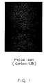
- Figure 1 illustrates the microstructure of a clad steel at the interface between the base material which is a 2-1/4 Cr, 1 Mo alloy steel or an AISI 4130 steel and the clad material which is Inconel Alloy 625.
- the interface between the base material and the cladding material is near the bottom in the figure, and the dark particles above the interface are the carbide (Cr 23 C 6 ) precipitants which cause the interface to be brittle.
- the cladding material is not allowed to be considered in making strength calculations for a structure such as illustrated in Figure 1.
- the cladding material is not considered in such strength calculations but only as a lining to protect against a corrosive environment then the resulting structure will be substantially larger than would be necessary if the structure did not contain a corrosive environment. This would necessitate redesign of API flanges and other associated equipment.
- clad steel in accordance with the present invention is shown in Figure 2. It should be noted that there are no large particles of precipitated carbide in the interface as contrasted with the large carbide particles shown in the clad steel represented in Figure 1.
- the preferred base material is a 2) chrome, 1 molybdenum nickel alloy steel with carbon from 8 to 15 points, all as shown in Table I.
- the preferred cladding material is Inconel 625 type nickel base alloy.
- the 625 type chemistry range used as the clad chemistry in this patent is as shown in Table II:
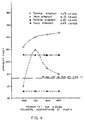
- Inconel 625 chemistry can be precipitation strengthened and were used in this application because wellhead equipment cannot be cold worked to gain strength. This allows the alloy to be precipitation hardened as shown in Figure 4. Note that the chemistry range of 625 is 3.1 to 4.1 percent Nb (niobium) but only 3.5 to 4.1 percent Nb offers adequate properties. Lower niobium contents of this alloy do not allow the alloy to be precipitation hardened in such a time/temperature combination that allows for co-treatment of the steel as also shown in Figure 4.
- the base steel utilized is a martensitic strengthened one, such as 2-1/4 Cr-1Mo, which has the necessary hardenability in heavy sections to meet API Type III strengths while allowing use of lower carbon for strengthening. These alloys are readily fabricated into wellhead equipment shape by forging. The tempering response of this type steel is shown in Figure 5.
- Another key to the process is the minimization of brittle chrome carbides forming at the clad-base interface.
- Figure 9 illustrates two types of tensile failure of tests conducted across the bond layer.
- Figure 9A shows a brittle failure near the bond layer which does not meet the 10 percent minimum elongation. The failure actually occurs in the 625 along a line of chromium carbides that form as a result of carbon migrating from the steel into the 625 during hipping and heat treatment.
- the cladding material is Inconel Alloy 625 wherein the Cb (columbium) content is between 3.5 and 4.1 to provide age hardenability.
- the present clad steel as described above was tested in tension in the base material, in the clad material and across the interface. Following is a summary of the results of typical testing: From these results it can be seen that the present clad steel maintains a yield strength above 75 ksi (517 MN/m 2 ) with ductility above ten percent throughout its entire structure.
- valves and other oil and gas pressure containing structure to be used on wells containing corrosive fluids such as hydrogen sulfide, sulfur dioxide or carbon dioxide, or combinations thereof can be made with the present clad structure.
- corrosive fluids such as hydrogen sulfide, sulfur dioxide or carbon dioxide, or combinations thereof.
- smaller valves and other wellhead structures can be used in compliance with the API specifications which materially reduces the cost and weight of each installation.
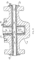
- valve body 10 shown in Figure 3 includes flow passages 12 and valve chamber 14 which are to be provided with a corrosion resistant lining.
- can 16 having thin tube 18, flat bottom 20 and thin sleeve 22 extending through the intermediate portion of tube 18 is inserted into valve chamber 14. Bottom 20 is sealed to the end of tube 18 as by welding and sleeve 22 is also sealed to tube 18 as by welding.
- Thin tube 24 is inserted through passages 12 and sleeve 22 as shown.
- Ring 26 is welded to the exterior of can 16 and to the exterior of body 10 and rings 28 and 30 are welded around the ends of tube 24 and to the exterior of body 10.
- Fill tube 32 extends through ring 26 and fill tube 34 extends through ring 30.
- the structure of can 16, tube 24 and their sealing rings 26, 28 and 30 provides a space 36 within the walls of passages 12 and chamber 14. This structure functions as a pressure transmitting yieldable mold or thin metal sealed structure as hereinafter explained. It is important that all of the welds in the structure of can 16, sleeve 22 and tube 24 be air tight and remain so during the consolidation step to exclude air from the heated metal powder.
- Body structure 10 in the valve structure shown in Figure 3 would be the base steel alloy, preferably the specific alloy mentioned above and definitely having less than 15 points of carbon on all of its surfaces that are to receive the cladding or lining.
- the steel alloy would have from 10 to 15 points or carbon but steel alloys having greater amounts of carbon may be used if all of the surfaces to receive the cladding or lining are subjected to a reduction or decarburization treatment which reduces the amount of carbon in these surfaces to the range specified above. In this manner the carbide precipitation is minimized and the strength of the interface is greatly improved.
- a vacuum is drawn thereon by connection of suitable means, such as a vacuum pump (not shown) to either or both of fill tubes 32 and 34. Sufficient vacuum should be drawn so that the amount of gases present in space 36 will not interfere with the formation of the desired consolidated metal lining.
- Space 36 within body cavities 12 and 14 is then filled through fill tubes 32 and 34 with the powdered metal of the corrosion resistant cladding material as set forth above. It is recommended that body 10 be vibrated during filling of space 36 so that it is completely filled with the metal powder before proceeding to the next step. It is preferred that the material of can 16, tube 24 and rings 26, 28 and 30 be of the same material as the cladding material. Also, it is suggested that space 36 be sufficiently large to provide a lining of consolidated metal which is sufficiently thick to allow for machining to the final internal shape without any depressions or holidays in the finished lining.
- valves may be secured thereon so that they may be closed when the vacuum drawing step is finished. Such valves are recommended to be leak proof when subjected to forming conditions.
- body 10 is placed in an autoclave (not shown) or other suitable device wherein it is subjected to forming temperature (2,000°F (1093°C) approximately) and pressure (15,000 psi (103421 KN/m 2 ) approximately). Body 10 is maintained at such temperature and pressure for a period of two hours and then is allowed to cool. It is believed important that the time during which body 10 is maintained at forming conditions in the autoclave should be limited and that the cooling and heating steps should not be extended unnecessarily.
- the length of the hip cycle and temperature be controlled to temperature less than 2200°F (1204°C) and a time of less than four hours at temperature.
- Such controls on the hip cycle plays a roll in limiting the formation of the chromium carbide.
- can 16 and tube 24 are expanded to compress the powdered metal against the walls of passages 12 and chamber 14.
- the heat and pressure cause the powdered metal to be consolidated into a solid lining within the body which is completely bonded to the body and has an interface of suitable physical properties as to allow the cladding or lining material to be considered in making the design calculations of the material needed to meet the specifications which are controlling for the particular structure.
- the method provides the combining of martensitic and austenitic alloys giving strength and corrosion resistance.
Landscapes
- Engineering & Computer Science (AREA)
- Chemical & Material Sciences (AREA)
- Life Sciences & Earth Sciences (AREA)
- Mechanical Engineering (AREA)
- Materials Engineering (AREA)
- Geology (AREA)
- Mining & Mineral Resources (AREA)
- Composite Materials (AREA)
- Metallurgy (AREA)
- General Life Sciences & Earth Sciences (AREA)
- Physics & Mathematics (AREA)
- Manufacturing & Machinery (AREA)
- Fluid Mechanics (AREA)
- Environmental & Geological Engineering (AREA)
- Geochemistry & Mineralogy (AREA)
- Organic Chemistry (AREA)
- Pressure Welding/Diffusion-Bonding (AREA)
- Separation By Low-Temperature Treatments (AREA)
- Inert Electrodes (AREA)
- Jib Cranes (AREA)
- Measurement Of Optical Distance (AREA)
- Laminated Bodies (AREA)
- Excavating Of Shafts Or Tunnels (AREA)
Claims (3)
Priority Applications (1)
| Application Number | Priority Date | Filing Date | Title |
|---|---|---|---|
| AT85300760T ATE44580T1 (de) | 1984-02-08 | 1985-02-05 | Bohrlochkopfstruktur und herstellungsverfahren einer derartigen struktur. |
Applications Claiming Priority (2)
| Application Number | Priority Date | Filing Date | Title |
|---|---|---|---|
| US57815384A | 1984-02-08 | 1984-02-08 | |
| US578153 | 1984-02-08 |
Publications (3)
| Publication Number | Publication Date |
|---|---|
| EP0152263A2 EP0152263A2 (de) | 1985-08-21 |
| EP0152263A3 EP0152263A3 (en) | 1986-11-20 |
| EP0152263B1 true EP0152263B1 (de) | 1989-07-12 |
Family
ID=24311660
Family Applications (1)
| Application Number | Title | Priority Date | Filing Date |
|---|---|---|---|
| EP85300760A Expired EP0152263B1 (de) | 1984-02-08 | 1985-02-05 | Bohrlochkopfstruktur und Herstellungsverfahren einer derartigen Struktur |
Country Status (9)
| Country | Link |
|---|---|
| EP (1) | EP0152263B1 (de) |
| JP (1) | JPS6138789A (de) |
| KR (1) | KR850006019A (de) |
| AT (1) | ATE44580T1 (de) |
| CA (1) | CA1259458A (de) |
| DE (1) | DE3571477D1 (de) |
| FI (1) | FI850510L (de) |
| NO (1) | NO850471L (de) |
| SG (1) | SG66689G (de) |
Cited By (4)
| Publication number | Priority date | Publication date | Assignee | Title |
|---|---|---|---|---|
| US6902005B2 (en) | 2002-02-15 | 2005-06-07 | Vetco Gray Inc. | Tubing annulus communication for vertical flow subsea well |
| US10221702B2 (en) | 2015-02-23 | 2019-03-05 | Kennametal Inc. | Imparting high-temperature wear resistance to turbine blade Z-notches |
| US10272497B2 (en) | 2013-03-15 | 2019-04-30 | Kennametal Inc. | Cladded articles and methods of making the same |
| US10562101B2 (en) | 2013-03-15 | 2020-02-18 | Kennametal Inc. | Methods of making metal matrix composite and alloy articles |
Families Citing this family (5)
| Publication number | Priority date | Publication date | Assignee | Title |
|---|---|---|---|---|
| JPH07117334B2 (ja) * | 1990-03-31 | 1995-12-18 | 株式会社前川製作所 | 垂直型冷却装置 |
| US20070068607A1 (en) * | 2005-09-29 | 2007-03-29 | Huff Philip A | Method for heat treating thick-walled forgings |
| EP1892372A1 (de) * | 2006-08-25 | 2008-02-27 | Cameron International Corporation | Ventilblock |
| CN101537526B (zh) * | 2008-03-17 | 2012-04-25 | 江苏信得石油机械有限公司 | 高级抗硫防喷器内腔表面合金堆焊方法 |
| US11117208B2 (en) | 2017-03-21 | 2021-09-14 | Kennametal Inc. | Imparting wear resistance to superalloy articles |
Family Cites Families (5)
| Publication number | Priority date | Publication date | Assignee | Title |
|---|---|---|---|---|
| US2874082A (en) * | 1957-04-18 | 1959-02-17 | Allegheny Ludlum Steel | Composite assembly of die steel core and stainless steel coating |
| US4065302A (en) * | 1975-12-29 | 1977-12-27 | The International Nickel Company, Inc. | Powdered metal consolidation method |
| GB2073783B (en) * | 1980-04-10 | 1984-10-10 | Cameron Iron Works Inc | Lining valves by hot isotatic pressing |
| CA1206130A (en) * | 1982-04-10 | 1986-06-17 | William L. Mccollough | Valve body with powdered metal lining and method for making the same |
| US4455352A (en) * | 1982-11-08 | 1984-06-19 | The Babcock & Wilcox Company | Materials system for high strength corrosion resistant bimetallic products |
-
1985
- 1985-02-04 CA CA000473477A patent/CA1259458A/en not_active Expired
- 1985-02-05 AT AT85300760T patent/ATE44580T1/de active
- 1985-02-05 DE DE8585300760T patent/DE3571477D1/de not_active Expired
- 1985-02-05 EP EP85300760A patent/EP0152263B1/de not_active Expired
- 1985-02-06 KR KR1019850000739A patent/KR850006019A/ko not_active Ceased
- 1985-02-07 FI FI850510A patent/FI850510L/fi not_active Application Discontinuation
- 1985-02-07 NO NO850471A patent/NO850471L/no unknown
- 1985-02-08 JP JP2338385A patent/JPS6138789A/ja active Pending
-
1989
- 1989-09-30 SG SG666/89A patent/SG66689G/en unknown
Cited By (4)
| Publication number | Priority date | Publication date | Assignee | Title |
|---|---|---|---|---|
| US6902005B2 (en) | 2002-02-15 | 2005-06-07 | Vetco Gray Inc. | Tubing annulus communication for vertical flow subsea well |
| US10272497B2 (en) | 2013-03-15 | 2019-04-30 | Kennametal Inc. | Cladded articles and methods of making the same |
| US10562101B2 (en) | 2013-03-15 | 2020-02-18 | Kennametal Inc. | Methods of making metal matrix composite and alloy articles |
| US10221702B2 (en) | 2015-02-23 | 2019-03-05 | Kennametal Inc. | Imparting high-temperature wear resistance to turbine blade Z-notches |
Also Published As
| Publication number | Publication date |
|---|---|
| SG66689G (en) | 1990-01-26 |
| DE3571477D1 (en) | 1989-08-17 |
| NO850471L (no) | 1985-08-09 |
| FI850510A7 (fi) | 1985-08-09 |
| EP0152263A3 (en) | 1986-11-20 |
| ATE44580T1 (de) | 1989-07-15 |
| FI850510A0 (fi) | 1985-02-07 |
| KR850006019A (ko) | 1985-09-28 |
| CA1259458A (en) | 1989-09-19 |
| FI850510L (fi) | 1985-08-09 |
| EP0152263A2 (de) | 1985-08-21 |
| JPS6138789A (ja) | 1986-02-24 |
Similar Documents
| Publication | Publication Date | Title |
|---|---|---|
| US4065302A (en) | Powdered metal consolidation method | |
| US6060180A (en) | Alloy having high corrosion resistance in environment of high corrosiveness, steel pipe of the same alloy and method of manufacturing the same steel pipe | |
| EP0283877B1 (de) | Verfahren zur Herstellung von beschichteten Metallrohre. | |
| CA1259458A (en) | Wellhead structure and method of producing same | |
| CA1169412A (en) | Method of producing a lined structure | |
| US4477955A (en) | Method of producing a lined structure | |
| US4601087A (en) | Method for cladding interior surfaces with externally prefabricated cladding material | |
| EP4263091B1 (de) | Isostatische heisspressherstellung von multimetallkomponenten für eine drucksteuerungsvorrichtung | |
| US4971101A (en) | Lined structure | |
| USRE32389E (en) | Method of producing a lined structure | |
| US10118259B1 (en) | Corrosion resistant bimetallic tube manufactured by a two-step process | |
| US5080325A (en) | Corrosion resistant stainless steel valve or fitting | |
| US5025975A (en) | Composite tubular products | |
| US20240167610A1 (en) | Tube For Subsea Application | |
| Bunch et al. | Hot Isostatic Pressing Process for Wellhead Components in High-Corrosion Environments | |
| Parker et al. | Microstructure and performance of 1.25 Cr0. 5Mo steel weldments | |
| Ermakov et al. | Cast Austenitic Steels for Cryogenic Technology | |
| Shiokawa et al. | HIP process of a valve body to near-net-shape using grade 91 powder | |
| Standard | Material data sheets for piping | |
| Chandhok et al. | Hot-Isostatic-Pressing for Making Parts from Prealloyed Powders | |
| Kovach et al. | Low-Heat Input Welding Process for Corrosion-Resistant Cladding of Wellhead Components | |
| Nakayama et al. | Development of high-strength, high-corrosion-resistant austenitic stainless steel for sour-gas service | |
| Gaddam | Material | |
| Campbell | Steels for Large Solid-propellant Rocket-motor Cases | |
| Houck et al. | The roll-diffusion bonding of structural shapes and panels |
Legal Events
| Date | Code | Title | Description |
|---|---|---|---|
| PUAI | Public reference made under article 153(3) epc to a published international application that has entered the european phase |
Free format text: ORIGINAL CODE: 0009012 |
|
| AK | Designated contracting states |
Designated state(s): AT BE CH DE FR GB IT LI LU NL SE |
|
| PUAL | Search report despatched |
Free format text: ORIGINAL CODE: 0009013 |
|
| AK | Designated contracting states |
Kind code of ref document: A3 Designated state(s): AT BE CH DE FR GB IT LI LU NL SE |
|
| 17P | Request for examination filed |
Effective date: 19870423 |
|
| 17Q | First examination report despatched |
Effective date: 19880113 |
|
| GRAA | (expected) grant |
Free format text: ORIGINAL CODE: 0009210 |
|
| AK | Designated contracting states |
Kind code of ref document: B1 Designated state(s): AT BE CH DE FR GB IT LI LU NL SE |
|
| PG25 | Lapsed in a contracting state [announced via postgrant information from national office to epo] |
Ref country code: LI Effective date: 19890712 Ref country code: IT Free format text: LAPSE BECAUSE OF FAILURE TO SUBMIT A TRANSLATION OF THE DESCRIPTION OR TO PAY THE FEE WITHIN THE PRESCRIBED TIME-LIMIT;WARNING: LAPSES OF ITALIAN PATENTS WITH EFFECTIVE DATE BEFORE 2007 MAY HAVE OCCURRED AT ANY TIME BEFORE 2007. THE CORRECT EFFECTIVE DATE MAY BE DIFFERENT FROM THE ONE RECORDED. Effective date: 19890712 Ref country code: CH Effective date: 19890712 Ref country code: BE Effective date: 19890712 |
|
| REF | Corresponds to: |
Ref document number: 44580 Country of ref document: AT Date of ref document: 19890715 Kind code of ref document: T |
|
| REF | Corresponds to: |
Ref document number: 3571477 Country of ref document: DE Date of ref document: 19890817 |
|
| ET | Fr: translation filed | ||
| REG | Reference to a national code |
Ref country code: CH Ref legal event code: PL |
|
| PG25 | Lapsed in a contracting state [announced via postgrant information from national office to epo] |
Ref country code: SE Effective date: 19900101 |
|
| PG25 | Lapsed in a contracting state [announced via postgrant information from national office to epo] |
Ref country code: LU Free format text: LAPSE BECAUSE OF NON-PAYMENT OF DUE FEES Effective date: 19900228 |
|
| PLBE | No opposition filed within time limit |
Free format text: ORIGINAL CODE: 0009261 |
|
| STAA | Information on the status of an ep patent application or granted ep patent |
Free format text: STATUS: NO OPPOSITION FILED WITHIN TIME LIMIT |
|
| 26N | No opposition filed | ||
| REG | Reference to a national code |
Ref country code: GB Ref legal event code: 732 |
|
| REG | Reference to a national code |
Ref country code: GB Ref legal event code: 732E |
|
| PGFP | Annual fee paid to national office [announced via postgrant information from national office to epo] |
Ref country code: NL Payment date: 19991213 Year of fee payment: 16 |
|
| PGFP | Annual fee paid to national office [announced via postgrant information from national office to epo] |
Ref country code: GB Payment date: 19991224 Year of fee payment: 16 |
|
| PGFP | Annual fee paid to national office [announced via postgrant information from national office to epo] |
Ref country code: AT Payment date: 19991227 Year of fee payment: 16 |
|
| PGFP | Annual fee paid to national office [announced via postgrant information from national office to epo] |
Ref country code: DE Payment date: 19991229 Year of fee payment: 16 |
|
| PGFP | Annual fee paid to national office [announced via postgrant information from national office to epo] |
Ref country code: FR Payment date: 20000207 Year of fee payment: 16 |
|
| PG25 | Lapsed in a contracting state [announced via postgrant information from national office to epo] |
Ref country code: GB Free format text: LAPSE BECAUSE OF NON-PAYMENT OF DUE FEES Effective date: 20010205 Ref country code: AT Free format text: LAPSE BECAUSE OF NON-PAYMENT OF DUE FEES Effective date: 20010205 |
|
| PG25 | Lapsed in a contracting state [announced via postgrant information from national office to epo] |
Ref country code: NL Free format text: LAPSE BECAUSE OF NON-PAYMENT OF DUE FEES Effective date: 20010901 |
|
| GBPC | Gb: european patent ceased through non-payment of renewal fee |
Effective date: 20010205 |
|
| PG25 | Lapsed in a contracting state [announced via postgrant information from national office to epo] |
Ref country code: FR Free format text: LAPSE BECAUSE OF NON-PAYMENT OF DUE FEES Effective date: 20011031 |
|
| NLV4 | Nl: lapsed or anulled due to non-payment of the annual fee |
Effective date: 20010901 |
|
| REG | Reference to a national code |
Ref country code: FR Ref legal event code: ST |
|
| PG25 | Lapsed in a contracting state [announced via postgrant information from national office to epo] |
Ref country code: DE Free format text: LAPSE BECAUSE OF NON-PAYMENT OF DUE FEES Effective date: 20011201 |