EP0152356A2 - Procédé et appareil pour délivrer à grande vitesse des articles en forme de bâtonnets - Google Patents
Procédé et appareil pour délivrer à grande vitesse des articles en forme de bâtonnets Download PDFInfo
- Publication number
- EP0152356A2 EP0152356A2 EP85400233A EP85400233A EP0152356A2 EP 0152356 A2 EP0152356 A2 EP 0152356A2 EP 85400233 A EP85400233 A EP 85400233A EP 85400233 A EP85400233 A EP 85400233A EP 0152356 A2 EP0152356 A2 EP 0152356A2
- Authority
- EP
- European Patent Office
- Prior art keywords
- bar
- passage
- articles
- rotary drum
- feeding
- Prior art date
- Legal status (The legal status is an assumption and is not a legal conclusion. Google has not performed a legal analysis and makes no representation as to the accuracy of the status listed.)
- Withdrawn
Links
Images
Classifications
-
- A—HUMAN NECESSITIES
- A24—TOBACCO; CIGARS; CIGARETTES; SIMULATED SMOKING DEVICES; SMOKERS' REQUISITES
- A24C—MACHINES FOR MAKING CIGARS OR CIGARETTES
- A24C5/00—Making cigarettes; Making tipping materials for, or attaching filters or mouthpieces to, cigars or cigarettes
- A24C5/32—Separating, ordering, counting or examining cigarettes; Regulating the feeding of tobacco according to rod or cigarette condition
- A24C5/322—Transporting cigarettes during manufacturing
- A24C5/325—Transporting cigarettes during manufacturing from a hopper
-
- B—PERFORMING OPERATIONS; TRANSPORTING
- B65—CONVEYING; PACKING; STORING; HANDLING THIN OR FILAMENTARY MATERIAL
- B65G—TRANSPORT OR STORAGE DEVICES, e.g. CONVEYORS FOR LOADING OR TIPPING, SHOP CONVEYOR SYSTEMS OR PNEUMATIC TUBE CONVEYORS
- B65G47/00—Article or material-handling devices associated with conveyors; Methods employing such devices
- B65G47/02—Devices for feeding articles or materials to conveyors
- B65G47/04—Devices for feeding articles or materials to conveyors for feeding articles
- B65G47/12—Devices for feeding articles or materials to conveyors for feeding articles from disorderly-arranged article piles or from loose assemblages of articles
- B65G47/14—Devices for feeding articles or materials to conveyors for feeding articles from disorderly-arranged article piles or from loose assemblages of articles arranging or orientating the articles by mechanical or pneumatic means during feeding
- B65G47/1407—Devices for feeding articles or materials to conveyors for feeding articles from disorderly-arranged article piles or from loose assemblages of articles arranging or orientating the articles by mechanical or pneumatic means during feeding the articles being fed from a container, e.g. a bowl
- B65G47/1442—Devices for feeding articles or materials to conveyors for feeding articles from disorderly-arranged article piles or from loose assemblages of articles arranging or orientating the articles by mechanical or pneumatic means during feeding the articles being fed from a container, e.g. a bowl by means of movement of the bottom or a part of the wall of the container
- B65G47/1471—Movement in one direction, substantially outwards
-
- B—PERFORMING OPERATIONS; TRANSPORTING
- B65—CONVEYING; PACKING; STORING; HANDLING THIN OR FILAMENTARY MATERIAL
- B65G—TRANSPORT OR STORAGE DEVICES, e.g. CONVEYORS FOR LOADING OR TIPPING, SHOP CONVEYOR SYSTEMS OR PNEUMATIC TUBE CONVEYORS
- B65G65/00—Loading or unloading
- B65G65/30—Methods or devices for filling or emptying bunkers, hoppers, tanks, or like containers, of interest apart from their use in particular chemical or physical processes or their application in particular machines, e.g. not covered by a single other subclass
- B65G65/34—Emptying devices
- B65G65/40—Devices for emptying otherwise than from the top
- B65G65/42—Devices for emptying otherwise than from the top using belt or chain conveyors
Definitions
- the present invention relates to a method and apparatus for feeding bar-like articles at a high rate, in particular, to a method and apparatus for high rate feeding filter plugs used in a cigarette making machine.
- Cigarette producing machines which can be operated at a high speed have recently been developed.
- a conventional method of taking out the filter plugs from a magazine comprises providing a passage at the bottom of the magazine; dropping the filter plugs in a line by gravity and successively feeding then into subsequent process.
- a forced feeding apparatus using a suction belt or suction roller as is disclosed in the Japanese Patent Application Laid Open N o.54-132969 has been proposed for enabling improved high rate feeding.
- this approach has disadvantages that a high vacuum and a large amount of air is required to provide an effective transportation capacity and that transportation capacity is decreased due to clogging of suction holes since the filter plug has only one point on the circumference thereof which is in contact with the suction belt and suction roller.
- a bar-like article feeding method in which bar-like articles are taken out from a container in a continuous line flow and then successively fed into recesses of a recessed rotary drum, the improvement comprising providing a vertical passage continuous to a feeding passage; successively feeding the bar-like articles along said feeding passage in such a manner that the bar-like articles are in contact with each other; and causing the bar-like articles to reach the recessed rotary drum, said bar-like articles being separated each other by gravity-dropping the bar-like articles along said vertical passage.
- a bar-like article feeding apparatus in which bar-like articles are taken out from a container in a continuous line flow and then successively fed into recesses of a recessed rotary drum, the improvement comprising an endless belt which is disposed at the bottom of the container which contains bar-like articles; substantially horizontal feeding passage which is formed by and between said endless belt and a guide thereabove; and a vertical dropping passage which is continuous to said horizontal passage via an arcuate passage and extends to the recessed rotary drum.
- a bar-like article feeding apparatus in which bar-like articles are taken out from a container in a continuous line flow and then successively fed into recesses of a recessed rotary drum, the improvement comprising an endless belt which is disposed at the bottom of the container which contains bar-like articles; a substantially horizontal feeding passage which is formed by and between said endless belt and a guide thereabove; a vertical dropping passage which is continuous to said horizontal passage via an arcuate passage and extends to the recessed rotary drum; an air nozzle which is disposed in close proximity with the outer periphery of the recessed drum at the lower end of the vertical dropping passage; and inclined surfaces on the outer periphery between the recesses of the recessed rotary drum, said inclined surfaces being linearly inclined towards a rear recess.
- the present invention has the afore-mentioned structure, the present invention has features that bar-like articles such as filter plug and the like can be taken out from a container at a high rate and the bar-like articles can be fed to a recessed rotary drum without causing deformation of the article and clogging of the transporting path.
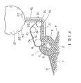
- FIG. 1 there is shown an apparatus of the present invention which is provided under a magazine 2 in which a multiplicity of filter plugs 1 are contained.
- a small chamber 3 Adjacent to the lower part of the magazine 2, there is provided a small chamber 3 in which a small number of (50 to 60) filter plugs are contained.
- An arcuate plate 5 forming a left side wall of the small chamber 3 is integral with the plate 4 which forms a left side bottom of the magazine.
- an arcuate plate 7 forming a right side wall of the small chamber 3 is integral with a plate 6 which forms the right side bottom of the magazine 2.
- a roller 8 is provided substantially midmost the small chamber 3 and is adapted to be rotated in a direction as shown by an arrow 9.
- An endless belt 10 is provided at the bottom of the small chamber 3 and is adapted to move around a drive roller 11, a guide 12 and rollers 13 and 14 in a direction as shown by an arrow 15.
- the endless belt 10 is substantially horizontally disposed between the drive roller 11 and the roller 13 and has a horizontal portion supported by the guide 12.
- a guide 16 is provided above the endless belt 10.
- a horizontal passage 17 along which a line of the filter plugs 1 are guided and successively transported from the small chamber 3 is defined.
- the guide 16 includes an arcuate passage 18 having an arc of 90° concentrical with the roller 13 following the horizontal part.
- the guide 16 includes a substantially vertical portion following the portion, which extends to the vicinity of the outer periphery of the recessed drum 21.
- a guide 20 is provided so that a vertical passage 19 having a spacing slightly larger than the diameter of the filter plug 1 is defined between the guides 20 and the vertical portion of the guide 16.
- a recessed drum 21 is provided below the vertical passage 19 so that the filter plugs 1 which are dispensed from the vertical passage 19 are successively received in recesses 22 and fed in a direction of an arrow 23.
- the filter plugs 1 contained in the magazine 2 fall in a downward direction by the effect of gravity and are successively moved into the small chamber 3. Since the roller 8 is rotated in a direction of the arrow 9, the filter plugs between the roller 8 and plate 7 are accelerated in a downward direction. The filter plugs between the roller 8 and the plate 5 are lifted in an upward direction. This causes the filter plugs 1 in the small chamber 3 to initiate to rotate around the roller 9 in a clockwise direction.
- the endless belt 10 is driven in the direction of the arrow 15 by means of the drive roller 11, the lowermost filter plugs 1 in the small chamber 3 are fed towards the entrance of the horizontal passage 17 and then transported in a line manner to the exit of the arcuate passage 18 along the horizontal passage 17.
- the roller 9 causes a clockwise rotation of the filter plugs 1 in the small chamber 3, a line of the closely disposed filter plugs is readily formed on the endless belt 10. Since the filter plugs which have not moved into the horizontal passage 17 will be readily moved in an upward direction due to the clockwise rotation of the filter plugs, the excessive filter plugs 1 are not pressed each other at the entrance of the horizontal passage 17 so that the entrance of the horizontal passage is prevented from being clogged.
- the filter plugs 1 which have been transported to the upper portion of the vertical passage 19 are accelerated by the gravity in the vertical passage 19.
- the spacings among the filter plugs 1 are gradually increased in the course of the falling in the vertical line 19.
- Each of the filter plugs 1 from the vertical passage 19 is moved into the recess 22 of the recessed drum 21 and is transported in a direction of an arrow 23 while it is retained in the recess by a sucking force which is applied via a hole (not shown) in the bottom of the recess 22.
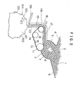
- Fig. 2 is an explanatory view showing another embodiment of an apparatus of the present invention.
- the parts identical with those in Fig. 1 are designated by like numerals while the changed parts, but corresponding to those in Fig. 1 are designated by numbers which are added by 100. Since the structure and the operation until the arcuate passage 18 in the apparatus of Fig. 1 are identical with those in Fig. 1, description of them are omitted.
- the vertical part of the guide 116 is made shorter at the lower end thereof.
- An air nozzle 126 is disposed in a proximate of the outer periphery of the recessed drum 121.
- the recessed drum 121 has on the outer periphery 124 inclined surfaces 125, each of them being substantially linearly descended toward an rearward direction.
- the subsequent filter plug 1 is gradually descended along the inclined surface 125 until it is moved into the subsequent recess 122.
- the spacing between the filter plug 1 and the guide 116 is enlarged so that it becomes easier for the filter plug 1 to pass below the guide 116.
- an air nozzle 126 is provided at the lower end of the guide 111 so that an compressed air is blown thereon for biasing the filter plug 1 in a rearward direction.
- the apparatus can accomplish the faster feeding than that in the embodiment of Fig. 1.
Landscapes
- Engineering & Computer Science (AREA)
- Mechanical Engineering (AREA)
- Filling Or Emptying Of Bunkers, Hoppers, And Tanks (AREA)
- Attitude Control For Articles On Conveyors (AREA)
- Manufacturing Of Cigar And Cigarette Tobacco (AREA)
- Cigarettes, Filters, And Manufacturing Of Filters (AREA)
Applications Claiming Priority (2)
| Application Number | Priority Date | Filing Date | Title |
|---|---|---|---|
| JP2438384A JPS60188238A (ja) | 1984-02-14 | 1984-02-14 | 棒状物品の高速送り方法及び装置 |
| JP24383/84 | 1984-02-14 |
Publications (2)
| Publication Number | Publication Date |
|---|---|
| EP0152356A2 true EP0152356A2 (fr) | 1985-08-21 |
| EP0152356A3 EP0152356A3 (fr) | 1985-09-18 |
Family
ID=12136656
Family Applications (1)
| Application Number | Title | Priority Date | Filing Date |
|---|---|---|---|
| EP85400233A Withdrawn EP0152356A3 (fr) | 1984-02-14 | 1985-02-13 | Procédé et appareil pour délivrer à grande vitesse des articles en forme de bâtonnets |
Country Status (2)
| Country | Link |
|---|---|
| EP (1) | EP0152356A3 (fr) |
| JP (1) | JPS60188238A (fr) |
Cited By (1)
| Publication number | Priority date | Publication date | Assignee | Title |
|---|---|---|---|---|
| EP0392289A3 (fr) * | 1989-04-12 | 1992-04-08 | Rieter Ingolstadt Spinnereimaschinenbau AG | Procédé et dispositif pour emmagasiner et isoler des tubes de bobine |
Families Citing this family (2)
| Publication number | Priority date | Publication date | Assignee | Title |
|---|---|---|---|---|
| CN102424248B (zh) * | 2011-07-07 | 2014-04-16 | 洛阳金诺机械工程有限公司 | 晶体材料加工中的自动上料装置 |
| CN105253584A (zh) * | 2015-09-28 | 2016-01-20 | 青岛萨沃特自动化设备有限公司 | 自动物料整理装置 |
Family Cites Families (7)
| Publication number | Priority date | Publication date | Assignee | Title |
|---|---|---|---|---|
| GB529683A (en) * | 1939-06-06 | 1940-11-26 | Desmond Walter Molins | Improvements in or relating to machines for making and packing cigarettes |
| DE955755C (de) * | 1954-10-02 | 1957-01-10 | Kurt Koerber & Co K G | Behaelter zur Entnahme von stabfoermigem Gut, insbesondere Zigaretten, Zigarillos od. dgl. |
| DE1002676B (de) * | 1955-04-29 | 1957-02-14 | Hauni Werke Koerber & Co Kg | Vorrichtung zum Einbringen von stabfoermigen Gegenstaenden wie Zigaretten, Zigarillos od. dgl. in Nuten umlaufender Foerdermittel |
| DE1027578B (de) * | 1956-04-06 | 1958-04-03 | Hauni Werke Koerber & Co Kg | Zigarettenmagazin |
| GB874700A (en) * | 1960-04-20 | 1961-08-10 | Tabak & Ind Masch | Cigarette-making machines feeding apparatus |
| CA1111873A (fr) * | 1978-03-29 | 1981-11-03 | Athos Cristiani | Dispositif d'avancement pour articles en forme de tige |
| JPS56137876A (en) * | 1980-03-01 | 1981-10-28 | Hauni Werke Koerber & Co Kg | Apparatus for transferring filter rod from storage part into take up drum |
-
1984
- 1984-02-14 JP JP2438384A patent/JPS60188238A/ja active Pending
-
1985
- 1985-02-13 EP EP85400233A patent/EP0152356A3/fr not_active Withdrawn
Cited By (1)
| Publication number | Priority date | Publication date | Assignee | Title |
|---|---|---|---|---|
| EP0392289A3 (fr) * | 1989-04-12 | 1992-04-08 | Rieter Ingolstadt Spinnereimaschinenbau AG | Procédé et dispositif pour emmagasiner et isoler des tubes de bobine |
Also Published As
| Publication number | Publication date |
|---|---|
| EP0152356A3 (fr) | 1985-09-18 |
| JPS60188238A (ja) | 1985-09-25 |
Similar Documents
| Publication | Publication Date | Title |
|---|---|---|
| US4241881A (en) | Fiber separation from pulp sheet stacks | |
| US7878366B2 (en) | Unit for filling containers with products, in particular, pharmaceutical products | |
| US4733520A (en) | Supply device with an eccentric vibrating cylindrical container for the supply of products to be packaged particularly by machines for blister packaging | |
| US6799413B2 (en) | Apparatus and methods for filling containers with pills | |
| JPH04215933A (ja) | パックに移し渡すラベルの運搬装置 | |
| US4790525A (en) | Apparatus and a method for separating sheet material | |
| US2819076A (en) | Paper-handling apparatus | |
| US3086771A (en) | Sheet feeding apparatus | |
| US5076291A (en) | Method and apparatus for detipping loose cigarettes | |
| JPH0194495A (ja) | 硬貨処理機の選別装置 | |
| US5730159A (en) | Unit for supplying layers of cigarettes | |
| GB1134683A (en) | Improvements in the manufacture of sheets of thermoplastic fibres for example glass fibres | |
| JPS59146579A (ja) | 個々のタバコ単位分を形成するための方法と装置 | |
| JPS61178812A (ja) | 包装機械の包装ラインに巻タバコを供給する装置 | |
| US4223685A (en) | Cigarette making machine hopper | |
| EP0545724A1 (fr) | Dispositif pour la prévention du blocage des canaux dans une trémie pour cigarettes | |
| JPS61245317A (ja) | 繊維材料の混合装置 | |
| JPS5863377A (ja) | たばこ製造装置 | |
| US6513645B2 (en) | Method and device for feeding elongated articles on a wrapping machine | |
| JPS60188238A (ja) | 棒状物品の高速送り方法及び装置 | |
| IL116822A (en) | Method for the manufacture and for the placing into trays of culture plugs | |
| US2727518A (en) | Cigarette making machine | |
| JP2004180605A (ja) | 棒状物品のホッパ装置 | |
| JP2532768B2 (ja) | ねじ素材整列送り出し装置 | |
| DE19844815A1 (de) | Vorrichtung zum Auftrennen von stabförmigen Artikeln der tabakverarbeitenden Industrie |
Legal Events
| Date | Code | Title | Description |
|---|---|---|---|
| PUAI | Public reference made under article 153(3) epc to a published international application that has entered the european phase |
Free format text: ORIGINAL CODE: 0009012 |
|
| PUAL | Search report despatched |
Free format text: ORIGINAL CODE: 0009013 |
|
| AK | Designated contracting states |
Designated state(s): DE GB IT |
|
| AK | Designated contracting states |
Designated state(s): DE GB IT |
|
| 17P | Request for examination filed |
Effective date: 19850813 |
|
| RAP1 | Party data changed (applicant data changed or rights of an application transferred) |
Owner name: JAPAN TOBACCO INC. |
|
| 17Q | First examination report despatched |
Effective date: 19861003 |
|
| STAA | Information on the status of an ep patent application or granted ep patent |
Free format text: STATUS: THE APPLICATION HAS BEEN WITHDRAWN |
|
| 18W | Application withdrawn |
Withdrawal date: 19861213 |
|
| RIN1 | Information on inventor provided before grant (corrected) |
Inventor name: HORIE, MOTONOBU Inventor name: SUZUKI, MINORU Inventor name: OGURA, SHINJI |