EP0152364A2 - Machine pour le prélèvement de blocs de fourrage dans un silo, avec des moyens d'entraînement perfectionnés - Google Patents
Machine pour le prélèvement de blocs de fourrage dans un silo, avec des moyens d'entraînement perfectionnés Download PDFInfo
- Publication number
- EP0152364A2 EP0152364A2 EP85440005A EP85440005A EP0152364A2 EP 0152364 A2 EP0152364 A2 EP 0152364A2 EP 85440005 A EP85440005 A EP 85440005A EP 85440005 A EP85440005 A EP 85440005A EP 0152364 A2 EP0152364 A2 EP 0152364A2
- Authority
- EP
- European Patent Office
- Prior art keywords
- arm
- support
- bearings
- pivot axis
- machine according
- Prior art date
- Legal status (The legal status is an assumption and is not a legal conclusion. Google has not performed a legal analysis and makes no representation as to the accuracy of the status listed.)
- Granted
Links
Images

Classifications
-
- A—HUMAN NECESSITIES
- A01—AGRICULTURE; FORESTRY; ANIMAL HUSBANDRY; HUNTING; TRAPPING; FISHING
- A01F—PROCESSING OF HARVESTED PRODUCE; HAY OR STRAW PRESSES; DEVICES FOR STORING AGRICULTURAL OR HORTICULTURAL PRODUCE
- A01F25/00—Storing agricultural or horticultural produce; Hanging-up harvested fruit
- A01F25/16—Arrangements in forage silos
- A01F25/20—Unloading arrangements
- A01F25/2027—Unloading arrangements for trench silos
- A01F25/2036—Cutting or handling arrangements for silage blocks
Definitions
- the present invention relates to machines for removing blocks of forage of parallelepiped shape in a horizontal silo, comprising in particular a frame provided at its lower part with teeth and, at a certain distance above them, an arm carrying at its outer end a cutting device.
- Said arm is articulated on a support and is movable with the latter in a substantially horizontal plane by means of a hydraulic cylinder, means including toothed wheels being also provided for rotating this arm in the opposite direction to the direction of rotation of said support.
- the object of the present invention is in particular to remedy the aforementioned drawback and, in general, to strengthen the drive means of the arm carrying the cutting device.
- an important characteristic of the invention consists in that the toothed wheels intended for the rotation of the arm carrying the cutting device are positioned on axes each of which is guided in two bearings placed on either side of the corresponding gear wheel, one of these two bearings being located on the side of the arm carrying the cutting device and the other on the side of the machine chassis.
- This guide ensures good stability to the axes carrying the toothed wheels. This improves the resistance of the latter and allows more power to be transmitted for cutting larger blocks.
- the machine according to the invention comprises in particular a chassis (1) forming a rigid frame.
- This chassis (1) has three coupling points for coupling to a not shown drive tractor. These coupling points consist of two lower pins (2 and 3) and an upper yoke (4).
- Said frame is also provided at its lower part with teeth (5) which extend in a substantially horizontal plane.
- an arm (6) which carries at its outer end a cutting device (7). The latter is articulated on said arm by means of a substantially vertical axis (8).
- It essentially consists of two parallel knives (9 and 10) which are driven in an alternating movement by means of a hydraulic motor (11) and eccentrics housed in a housing (12). These knives (9 and 10) extend vertically practically to the teeth (5) provided at the bottom of the frame (1). These two knives (9 and 10) could be replaced by a single knife.
- the arm (6) carrying the cutting device (7) is articulated on a support (13) by means of a substantially vertical axis (14).
- This support (13) is itself articulated on a substantially vertical axis (15) which is integral with the machine frame (1).
- Said support and the arm (6) can be moved around this articulation axis (15) by means of a double rod hydraulic cylinder (16) which is fixed to the chassis (1).
- the cylinder body (16) is provided with a rack (17) which meshes with a wheel or toothed crown (18) fixed to the lower part of the support (13) by means of screws (19). (figure 3).
- This rack (17) can thus be moved by means of the hydraulic cylinder (16), the control of which is carried out from the seat of the tractor.
- these means are constituted by three toothed wheels (27, 28 and 29).
- the wheel (27) is integral with the support arm (6).
- the wheel (28) is rigidly fixed on the hinge pin (15) which is integral with the chassis (1).
- the wheel (29) is mounted to rotate freely on an axis (30) integral with the support (13).
- This intermediate wheel (29) provides the connection between the two wheels (27 and 28) mentioned above. It could be replaced by a drive chain (example not shown) passing over the wheels (27 and 28).
- each of the axes (14, 15 and 30) on which the toothed wheels (27, 28 and 29) are positioned is guided in two bearings (31 and 32, 33 and 34, 35 and 36) placed on either side of the corresponding toothed wheel, one of these bearings being located on the side of the arm (6) carrying the cutting device (7) and the other on the side of the chassis (1) of the machine ( Figures 3 and 4).
- the guide according to the invention allows great power to be transmitted by these toothed wheels (27, 28 and 29) arranged on the axes (14, 15 and 30). The latter thus perfectly resist the large forces exerted on them as a result of the movement of the carrying arm (6) of the cutting device (7).
- these efforts have a good effect on the chassis (1) which is designed so that it can easily withstand it.
- the toothed wheels (27, 28 and 29) are housed inside the support (13).
- the guide bearings (31 to 36) of the three axes (14, 15 and 30) are provided in the upper wall and the lower wall of this support (13).
- Each guide bearing (33 and 34) of the support (13) on the pivot axis (15) integral with the chassis (1) has a bore (37 and 38). In each of these bores (37 and 38) is housed a tapered roller bearing (39 and 40) positioned elsewhere on the pivot axis (15).
- a positioning sleeve (41) and the toothed wheel (28) which is secured to the axis (15) by means of grooves (42).
- the holding in place of these different parts on the pivot axis (15) is ensured by a nut (43) screwing onto the threaded end (44) of said axis.
- a seal (45) At the lower part of the pivot axis (15) is provided a seal (45) to seal the support (13), while the bore (37) of the upper bearing (33) is closed by means of 'a cover (46).
- the intermediate gear (29). is mounted free in rotation on its axis (30) by means of adjoining needles (47).
- Each guide bearing (35 and 36) of this axis (30) has a bore (48 and 49). Said axis is housed in these bores (48 and 49) and is locked there by means of a circlip (50).
- the pivot axis (14) of the support arm (6) on the support (13) is integral with said support arm.
- This axis (14) is made in two parts (51 and 52) to facilitate machining. These parts are linked together by means of grooves (53).
- the outer part (51) has a flange (54) for fixing to the support arm (6) using screws (55) and pins (56).
- This pivot axis (14) is guided externally by means of tapered roller bearings (57 and 58) in bores (59 and 60) of the bearings (31 and 32).
- the toothed wheel (27) is located between these two bearings (57 and 58) and is secured to the inner part (52). Of the axis (14) by means of the aforementioned grooves (53) and a circlip ( 61).
- This pivot axis (14) is held in place by means I a shoulder (62) pressing against the upper bearing (57) and a nut (63) screwing onto the threaded end (64) and pressing against the lower bearing (58).
- the bore (59) of the bearing (31) is closed by means of the flange (54) of the outer part (51) of the pivot axis (14).
- Said pivot axis also has an internal bore (65). It is crossed by a rod (66) fixed on the support (13) by means of a pin (67). This pin (67) is used at the same time for mounting a washer (68) which makes it possible to close the bore (60) of the lower bearing (32) provided in the support (13).
- the rod (66) crosses the pivot axis (14) and the support arm (6). Its upper end is connected to rods (69, 70 and 71) which orient the cutting device (7) around its hinge axis (8), so that the knives (9 and 10) are always directed in the direction of travel.
- the device according to the invention is coupled to a tractor. With the help of the latter the teeth (5) of the lower part of the chassis (1) are pressed into the fodder.
- the two knives (9 and 10) are then driven by means of the hydraulic motor (11) and moved using the support arm (6) along the path (T), for cutting a block having a substantially shaped parallelepiped.
- the cut block can then be removed from the silo and transported to the feeding place where it can be distributed immediately or stored as it is for several days.
- the machine according to the invention can also be equipped with a shredding and distribution device.
Landscapes
- Life Sciences & Earth Sciences (AREA)
- Environmental Sciences (AREA)
- Filling Or Emptying Of Bunkers, Hoppers, And Tanks (AREA)
- Threshing Machine Elements (AREA)
- Harvester Elements (AREA)
- Road Paving Machines (AREA)
Abstract
Description
- La présente invention concerne les machines pour le prélèvement de blocs de fourrage de forme parallélépipédique dans un silo horizontal, comportant notamment un châssis pourvu à sa partie inférieure de dents et, à une certaine distance au-dessus de celles-ci, d'un bras portant à son extrémité extérieure un dispositif de coupe. Ledit bras est articulé sur un support et est déplaçable avec ce dernier dans un plan sensiblement horizontal à l'aide d'un vérin hydraulique, des moyens incluant des roues dentées étant par ailleurs prévus pour faire tourner ce bras dans le sens opposé au sens de rotation dudit support.
- Les machines de ce genre qui sont actuellement connues, réalisent un très bon travail. Toutefois, la puissance transmissible par les moyens d'entraînement du bras porteur du dispositif de coupe n'est pas suffisante pour le découpage de blocs de gros volume dans des silos bien tassés.
- La présente invention a notamment pour but de remédier à l'inconvénient précité et, d'une manière générale, de renforcer les moyens d'entraînement du bras portant le dispositif de coupe.
- A cet effet, une importante caractéristique de l'invention consiste en ce que les roues dentées destinées à la rotation du bras portant le dispositif de coupe sont positionnées sur des axes dont chacun est guidé dans deux paliers placés de part et d'autre de la roue dentée correspondante, un de ces deux paliers se situant du côté du bras portant le dispositif de coupe et l'autre du côté du châssis de la machine.
- Ce guidage assure une bonne stabilité aux axes portant les roues dentées. Cela améliore la tenue de ces dernières et permet de transmettre plus de puissance pour le découpage de blocs plus volumineux.
- D'autres caractéristiques et avantages de l'invention ressortiront de la description ci-après, avec référence aux dessins annexés qui représentent, à titre d'exemple non limitatif, une forme de réalisation de l'invention.
- Dans ces dessins :
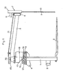
- - La figure 1 représente une vue de côté, avec une coupe partielle, d'une machine selon l'invention,
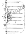
- - La figure 2 représente une vue de dessus de cette machine,
- - La figure 3 représente, à plus grande échelle, une coupe suivant le plan brisé III-III de la figure 2,
- - La figure 4 représente, à plus grande échelle, une coupe suivant le plan IV-IV de la figure 3.
- Telle qu'elle est représentée sur les figures 1 et 2, la machine selon l'invention comprend notamment un châssis (1) formant un cadre rigide. Ce châssis (1) comporte trois points d'accouplement pour l'attelage à un tracteur d'entraînement non représenté. Ces points d'accouplement sont constitués par deux tourillons inférieurs (2 et 3) et une chape supérieure (4). Ledit châssis est également pourvu à sa partie inférieure de dents (5) qui s'étendent dans un plan sensiblement horizontal. A sa partie supérieure est prévu un bras (6) qui porte à son extrémité extérieure un dispositif de coupe (7). Celui-ci est articulé sur ledit bras au moyen d'un axe sensiblement vertical (8). Il se compose essentiellement de deux couteaux parallèles (9 et 10) qui sont entraînés en un mouvement alternatif au moyen d'un moteur hydraulique (11) et d'excentriques logés dans un boîtier (12). Ces couteaux (9 et 10) s'étendent verticalement pratiquement jusqu'aux dents (5) prévues à la partie inférieure du châssis (1). Ces deux couteaux (9 et 10) pourraient être remplacés par un seul couteau.
- Le bras (6) portant le dispositif de coupe (7) est articulé sur un support (13) au moyen d'un axe sensiblement vertical (14). Ce support (13) est lui-même articulé sur un axe sensiblement vertical (15) qui est solidaire du châssis (1) de la machine. Ledit support et le bras (6) peuvent être déplacés autour de cet axe d'articulation (15) au moyen d'un vérin hydraulique à double tige (16) qui est fixé sur le châssis (1). En vue de ce déplacement, le corps du vérin (16) est muni d'une crémaillère (17) qui engrène avec une roue ou couronne dentée (18) fixée à la partie inférieure du support (13) au moyen de vis (19) (figure 3). Cette crémaillère (17) peut ainsi être déplacée au moyen du vérin hydraulique (16) dont la commande s'effectue à partir du siège du tracteur. Elle entraîne alors la couronne dentée (18), le support (13) et, par l'intermédiaire de ce dernier, le bras porteur (6) du dispositif de coupe (7) autour de l'axe d'articulation (15) solidaire du châssis (1). La fixation de la crémaillère (17) sur le corps du vérin (16) est réalisée au moyen de goupilles (20). Celles-ci lient la crémaillère à des pattes (21 et 22) qui sont soudées sur ledit corps du vérin (16). Ce vérin (16) est guidé en translation au moyen d'une butée (23). Cette butée est constituée par un axe (24) portant un galet (25), ledit axe étant fixé sur le châssis (1) au moyen d'un boulon (26).
- Dans le support (13) sont par ailleurs prévus des moyens pour faire tourner le bras porteur (6) du dispositif de coupe (7) autour de son axe d'articulation (14) avec le support (13), en même temps qu'il tourne avec ce dernier. La longueur du bras (6) est supérieure à celle cb ce sapport.
- Tel que cela ressort de la figure 2, ces moyens sont constitués par trois roues dentées (27, 28 et 29). La roue (27) est solidaire du bras porteur (6). La roue (28) est fixée rigidement sur l'axe d'articulation (15) qui est solidaire du châssis (1). Enfin, la roue (29) est montée libre en rotation sur un axe (30) solidaire du support (13). Cette roue intermédiaire (29) assure la liaison entre les deux roues (27 et 28) précitées. Elle pourrait être remplacée par une chaîne d'entraînement (exemple non représenté) passant sur les roues (27 et 28). En raison de la disposition de ces roues dentées (27, 28 et 29), la rotation du bras porteur (6) autour de son axe (14) s'effectue dans le sens opposé au sens de rotation du support (13) autour de son axe d'articulation (15) avec le châssis (1). En sus, ces deux mouvements de rotation sont synchronisés de telle sorte que la vitesse de rotation du bras porteur (6) autour de son axe d'articulation (14) est égale à quatre tiers de la vitesse de rotation du support (13) autour de son axe d'articulation (15) avec le châssis (1). Grâce à ces mouvements synchronisés le support (13) et le bras porteur (6) déplacent le dispositif de coupe (7) suivant une trajectoire (T) en forme de U, en vue du découpage de blocs de forme parallélépipédique.
- Conformément à une importante caractéristique de l'invention, chacun des axes (14, 15 et 30) sur lesquels sont positionnées les roues dentées (27, 28 et 29) est guidé dans deux paliers (31 et 32, 33 et 34, 35 et 36) placés de part et d'autre de la roue dentée correspondante, un de ces paliers se situant du côté du bras (6) portant le dispositif de coupe (7) et l'autre du côté du châssis (1) de la machine (figures 3 et 4). Contrairement à un montage en porte à faux, le guidage selon l'invention permet de transmettre une grande puissance par ces roues dentées (27, 28 et 29) disposées sur les axes (14, 15 et 30). Ces derniers résistent ainsi parfaitement aux importants efforts s'exerçant sur eux par suite du déplacement du bras porteur (6) du dispositif de coupe (7). De plus, ces efforts se répercutent bien sur le châssis (1) qui est conçu de manière à pouvoir y résister facilement.
- Selon une autre caractéristique de l'invention, les roues dentées (27, 28 et 29) sont logées à l'intérieur du support (13). Celui-ci forme un carter pratiquement étanche qui assure leur protection. Les paliers de guidage (31 à 36) des trois axes (14, 15 et 30) sont prévus dans la paroi supérieure et la paroi inférieure de ce support (13). Chaque palier de guidage (33 et 34) du support (13) sur l'axe de pivotement (15) solidaire du châssis (1), présente un alésage (37 et 38). Dans chacun de ces alésages (37 et 38) est logé un roulement à rouleaux coniques (39 et 40) positionné par ailleurs sur l'axe de pivotement (15). Entre ces deux roulements (39 et 40) sont prévues une douille de positionnement (41) et la roue dentée (28) qui est solidarisée de l'axe (15) à l'aide de cannelures (42). Le maintien en place de ces différentes pièces sur l'axe de pivotement (15) est assuré par un écrou (43) se vissant sur l'extrémité filetée (44) dudit axe. A la partie inférieure de l'axe de pivotement (15) est prévu un joint (45) pour assurer l'étanchéité du support (13), tandis que l'alésage (37) du palier supérieur (33) est obturé au moyen d'un couvercle (46).
- Comme cela ressort de la figure 4, la roue dentée intermédiaire (29). est montée libre en rotation sur son axe (30) au moyen d'aiguilles jointives (47). Chaque palier de guidage (35 et 36) de cet axe (30) présente un alésage (48 et 49). Ledit axe est logé dans ces alésages (48 et 49) et y est bloqué au moyen d'un circlips (50).
- L'axe de pivotement (14) du bras porteur (6) sur le support (13) est solidaire dudit bras porteur. Cet axe (14) est réalisé en deux parties (51 et 52) pour en faciliter l'usinage. Ces parties sont liées entre elles au moyen de cannelures (53). La partie extérieure (51) comporte un flasque (54) pour la fixation sur le bras porteur (6) à l'aide de vis (55) et de goupilles (56). Cet axe de pivotement (14) est guidé extérieurement au moyen de roulements à rouleaux coniques (57 et 58) dans des alésages (59 et 60) des paliers (31 et 32). La roue dentée (27) se situe entre ces deux roulements (57 et 58) et est-solidarisée de la partie intérieure (52).de l'axe (14) au moyen des cannelures (53) précitées et d'un circlips (61). Cet axe de pivotement (14) est maintenu en place au moyen j'un épaulement (62) s'appuyant contre le roulement supérieur (57) et un écrou (63) se vissant sur l'extrémité filetée (64) et s'appuyant contre le roulement inférieur (58). L'alésage (59) du palier (31) est fermé au moyen du flasque (54) de la partie extérieure (51) de l'axe de pivotement (14).
- Ledit axe de pivotement comporte en sus un alésage intérieur (65). Celui-ci est traversé par une tige (66) fixée sur le support (13) au moyen d'une goupille (67). Cette goupille (67) sert en même temps au montage d'une rondelle (68) qui permet d'obturer l'alésage (60) du palier inférieur (32) prévu dans le support (13). La tige (66) traverse l'axe de pivotement (14) et le bras porteur (6). Son extrémité supérieure est reliée à des tringles (69, 70 et 71) qui orientent le dispositif de coupe (7) autour de son axe d'articulation (8), de sorte que les couteaux (9 et 10) soient toujours dirigés dans la direction de déplacement.
- Pour l'extraction d'un bloc de fourrage, le dispositif conforme à l'invention est accouplé à un tracteur. A l'aide de ce dernier les dents (5) de la partie inférieure du châssis (1) sont enfoncées dans le fourrage. Les deux couteaux (9 et 10) sont alors entraînés au moyen du moteur hydraulique (11) et déplacés à l'aide du bras porteur (6) suivant la trajectoire (T), en vue du découpage d'un bloc ayant une forme sensiblement parallélépipédique.
- Le bloc découpé peut alors être retiré du silo et transporté jusqu'au lieu d'affouragement où il peut être distribué immédiatement ou être entreposé tel quel pendant plusieurs jours. La machine selon l'invention peut également être équipée d'un dispositif de déchiquetage et de distribution.
- Il est bien évident qu'on pourra apporter à l'exemple de réalisation décrit ci-dessus divers perfectionnements, modifications ou additions ou remplacer certains éléments par des éléments équivalents sans pour autant sortir du cadre de la présente invention.
Claims (7)
Priority Applications (1)
| Application Number | Priority Date | Filing Date | Title |
|---|---|---|---|
| AT85440005T ATE46999T1 (de) | 1984-02-07 | 1985-02-06 | Triebwerk eines silageblockschneiders. |
Applications Claiming Priority (2)
| Application Number | Priority Date | Filing Date | Title |
|---|---|---|---|
| FR8401980 | 1984-02-07 | ||
| FR8401980A FR2559022B1 (fr) | 1984-02-07 | 1984-02-07 | Machine pour le prelevement de blocs de fourrage dans un silo, avec des moyens d'entrainement perfectionnes. |
Publications (3)
| Publication Number | Publication Date |
|---|---|
| EP0152364A2 true EP0152364A2 (fr) | 1985-08-21 |
| EP0152364A3 EP0152364A3 (en) | 1987-05-06 |
| EP0152364B1 EP0152364B1 (fr) | 1989-10-11 |
Family
ID=9300894
Family Applications (1)
| Application Number | Title | Priority Date | Filing Date |
|---|---|---|---|
| EP85440005A Expired EP0152364B1 (fr) | 1984-02-07 | 1985-02-06 | Machine pour le prélèvement de blocs de fourrage dans un silo, avec des moyens d'entraînement perfectionnés |
Country Status (6)
| Country | Link |
|---|---|
| EP (1) | EP0152364B1 (fr) |
| AT (1) | ATE46999T1 (fr) |
| DE (1) | DE3573508D1 (fr) |
| DK (1) | DK165767C (fr) |
| ES (1) | ES8605136A1 (fr) |
| FR (1) | FR2559022B1 (fr) |
Families Citing this family (1)
| Publication number | Priority date | Publication date | Assignee | Title |
|---|---|---|---|---|
| RU2261579C1 (ru) * | 2004-03-23 | 2005-10-10 | Государственное научное учреждение "Всероссийский научно-исследовательский институт электрификации сельского хозяйства" (ГНУ ВИЭСХ) | Устройство для отрезания и погрузки силоса и сенажа |
Family Cites Families (2)
| Publication number | Priority date | Publication date | Assignee | Title |
|---|---|---|---|---|
| FR2509957A1 (fr) * | 1981-07-23 | 1983-01-28 | Kuhn Sa | Machine pour le prelevement de blocs de fourrage dans un silo |
| DE3218422A1 (de) * | 1982-05-15 | 1983-11-17 | H. Niemeyer Söhne GmbH & Co KG, 4446 Hörstel | Geraet zum auschneiden und entnehmen von silagefutterbloecken |
-
1984
- 1984-02-07 FR FR8401980A patent/FR2559022B1/fr not_active Expired
-
1985
- 1985-01-18 ES ES539667A patent/ES8605136A1/es not_active Expired
- 1985-01-31 DK DK042185A patent/DK165767C/da not_active IP Right Cessation
- 1985-02-06 DE DE8585440005T patent/DE3573508D1/de not_active Expired
- 1985-02-06 AT AT85440005T patent/ATE46999T1/de not_active IP Right Cessation
- 1985-02-06 EP EP85440005A patent/EP0152364B1/fr not_active Expired
Also Published As
| Publication number | Publication date |
|---|---|
| EP0152364B1 (fr) | 1989-10-11 |
| DK42185D0 (da) | 1985-01-31 |
| ATE46999T1 (de) | 1989-10-15 |
| ES539667A0 (es) | 1986-04-01 |
| EP0152364A3 (en) | 1987-05-06 |
| FR2559022A1 (fr) | 1985-08-09 |
| DK165767B (da) | 1993-01-18 |
| DK42185A (da) | 1985-08-08 |
| DE3573508D1 (en) | 1989-11-16 |
| FR2559022B1 (fr) | 1986-08-01 |
| DK165767C (da) | 1993-06-14 |
| ES8605136A1 (es) | 1986-04-01 |
Similar Documents
| Publication | Publication Date | Title |
|---|---|---|
| EP0171341B1 (fr) | Faucheuse rotative | |
| EP0408088B1 (fr) | Faucheuse rotative | |
| CA1102221A (fr) | Faucheuse a disques entraines par le bas | |
| EP0337909B1 (fr) | Faucheuse à entraînement direct | |
| FR2668881A1 (fr) | Machine agricole, en particulier faucheuse, s'adaptant aisement au relief du terrain et comportant un carter pivotant. | |
| FR2559342A1 (fr) | Transmission pour tondeuse a gazon | |
| FR2532516A1 (fr) | Faucheuse | |
| EP0152364B1 (fr) | Machine pour le prélèvement de blocs de fourrage dans un silo, avec des moyens d'entraînement perfectionnés | |
| EP0162795B1 (fr) | Moyens d'entraînement de machines pour le prélèvement de blocs de fourrage | |
| FR2685162A1 (fr) | Dispositif cueilleur repliable pour la recolte du mauis ou plantes similaires. | |
| EP0013058A1 (fr) | Appareil de levage et mécanisme de coupe de cet appareil de levage | |
| EP0152363B1 (fr) | Machines pour le prélèvement de blocs de fourrage dans un silo | |
| EP0071555B1 (fr) | Machine pour le prélèvement de blocs de fourrage dans un silo | |
| EP4183242B1 (fr) | Machine de fauche avec au moins un dispositif de groupage à entrainement amélioré | |
| EP0543688B1 (fr) | Dispositif de coupe pour désileuse | |
| EP0338653B1 (fr) | Dispositif de chargement à système de coupe latéral pour désileuses distributrices | |
| EP0279760B1 (fr) | Machine pour le prélèvement de blocs de fourrage dans un silo | |
| EP0446535A1 (fr) | Appareil rotatif de travail du sol | |
| FR2559992A1 (fr) | Appareil de support de barre de coupe et dispositif a barre de coupe pour faucheuse rotative | |
| FR2712767A1 (fr) | Machine de fenaison transposable dans plusieurs positions de travail. | |
| FR2703559A1 (fr) | Herse rotative comportant des éléments repliables pour les déplacements. | |
| FR2621374A1 (fr) | Transmission mecanique pour machine supportant des efforts resistants variables, par exemple un broyeur d'ordures menageres | |
| FR2613580A1 (fr) | Faucheuse rotative | |
| FR2546150A1 (fr) | Accessoire d'appareil de levage formant grappin | |
| FR2508759A1 (fr) | Machine a vendanger |
Legal Events
| Date | Code | Title | Description |
|---|---|---|---|
| PUAI | Public reference made under article 153(3) epc to a published international application that has entered the european phase |
Free format text: ORIGINAL CODE: 0009012 |
|
| AK | Designated contracting states |
Designated state(s): AT BE DE GB IT NL SE |
|
| PUAL | Search report despatched |
Free format text: ORIGINAL CODE: 0009013 |
|
| AK | Designated contracting states |
Kind code of ref document: A3 Designated state(s): AT BE DE GB IT NL SE |
|
| 17P | Request for examination filed |
Effective date: 19870924 |
|
| 17Q | First examination report despatched |
Effective date: 19880608 |
|
| GRAA | (expected) grant |
Free format text: ORIGINAL CODE: 0009210 |
|
| AK | Designated contracting states |
Kind code of ref document: B1 Designated state(s): AT BE DE GB IT NL SE |
|
| REF | Corresponds to: |
Ref document number: 46999 Country of ref document: AT Date of ref document: 19891015 Kind code of ref document: T |
|
| ITF | It: translation for a ep patent filed | ||
| GBT | Gb: translation of ep patent filed (gb section 77(6)(a)/1977) | ||
| REF | Corresponds to: |
Ref document number: 3573508 Country of ref document: DE Date of ref document: 19891116 |
|
| PLBE | No opposition filed within time limit |
Free format text: ORIGINAL CODE: 0009261 |
|
| STAA | Information on the status of an ep patent application or granted ep patent |
Free format text: STATUS: NO OPPOSITION FILED WITHIN TIME LIMIT |
|
| 26N | No opposition filed | ||
| ITTA | It: last paid annual fee | ||
| PGFP | Annual fee paid to national office [announced via postgrant information from national office to epo] |
Ref country code: GB Payment date: 19920205 Year of fee payment: 8 |
|
| PG25 | Lapsed in a contracting state [announced via postgrant information from national office to epo] |
Ref country code: GB Effective date: 19930206 |
|
| PGFP | Annual fee paid to national office [announced via postgrant information from national office to epo] |
Ref country code: SE Payment date: 19930224 Year of fee payment: 9 |
|
| GBPC | Gb: european patent ceased through non-payment of renewal fee |
Effective date: 19930206 |
|
| PG25 | Lapsed in a contracting state [announced via postgrant information from national office to epo] |
Ref country code: SE Effective date: 19940207 |
|
| PGFP | Annual fee paid to national office [announced via postgrant information from national office to epo] |
Ref country code: BE Payment date: 19940314 Year of fee payment: 10 |
|
| EUG | Se: european patent has lapsed |
Ref document number: 85440005.8 Effective date: 19940910 |
|
| PG25 | Lapsed in a contracting state [announced via postgrant information from national office to epo] |
Ref country code: BE Effective date: 19950228 |
|
| BERE | Be: lapsed |
Owner name: S.A. KUHN Effective date: 19950228 |
|
| PGFP | Annual fee paid to national office [announced via postgrant information from national office to epo] |
Ref country code: AT Payment date: 19990122 Year of fee payment: 15 |
|
| PGFP | Annual fee paid to national office [announced via postgrant information from national office to epo] |
Ref country code: DE Payment date: 19990126 Year of fee payment: 15 |
|
| PGFP | Annual fee paid to national office [announced via postgrant information from national office to epo] |
Ref country code: NL Payment date: 19990128 Year of fee payment: 15 |
|
| PG25 | Lapsed in a contracting state [announced via postgrant information from national office to epo] |
Ref country code: AT Free format text: LAPSE BECAUSE OF NON-PAYMENT OF DUE FEES Effective date: 20000206 |
|
| PG25 | Lapsed in a contracting state [announced via postgrant information from national office to epo] |
Ref country code: NL Free format text: LAPSE BECAUSE OF NON-PAYMENT OF DUE FEES Effective date: 20000901 |
|
| NLV4 | Nl: lapsed or anulled due to non-payment of the annual fee |
Effective date: 20000901 |
|
| PG25 | Lapsed in a contracting state [announced via postgrant information from national office to epo] |
Ref country code: DE Free format text: LAPSE BECAUSE OF NON-PAYMENT OF DUE FEES Effective date: 20001201 |