EP0152375B1 - Sprühkopf einer Pulverauftragsvorrichtung - Google Patents
Sprühkopf einer Pulverauftragsvorrichtung Download PDFInfo
- Publication number
- EP0152375B1 EP0152375B1 EP85810036A EP85810036A EP0152375B1 EP 0152375 B1 EP0152375 B1 EP 0152375B1 EP 85810036 A EP85810036 A EP 85810036A EP 85810036 A EP85810036 A EP 85810036A EP 0152375 B1 EP0152375 B1 EP 0152375B1
- Authority
- EP
- European Patent Office
- Prior art keywords
- powder
- spray head
- head according
- screen
- line
- Prior art date
- Legal status (The legal status is an assumption and is not a legal conclusion. Google has not performed a legal analysis and makes no representation as to the accuracy of the status listed.)
- Expired
Links
Images
Classifications
-
- B—PERFORMING OPERATIONS; TRANSPORTING
- B05—SPRAYING OR ATOMISING IN GENERAL; APPLYING FLUENT MATERIALS TO SURFACES, IN GENERAL
- B05B—SPRAYING APPARATUS; ATOMISING APPARATUS; NOZZLES
- B05B1/00—Nozzles, spray heads or other outlets, with or without auxiliary devices such as valves, heating means
- B05B1/30—Nozzles, spray heads or other outlets, with or without auxiliary devices such as valves, heating means designed to control volume of flow, e.g. with adjustable passages
- B05B1/32—Nozzles, spray heads or other outlets, with or without auxiliary devices such as valves, heating means designed to control volume of flow, e.g. with adjustable passages in which a valve member forms part of the outlet opening
- B05B1/326—Gate valves; Sliding valves; Cocks
-
- B—PERFORMING OPERATIONS; TRANSPORTING
- B05—SPRAYING OR ATOMISING IN GENERAL; APPLYING FLUENT MATERIALS TO SURFACES, IN GENERAL
- B05B—SPRAYING APPARATUS; ATOMISING APPARATUS; NOZZLES
- B05B14/00—Arrangements for collecting, re-using or eliminating excess spraying material
- B05B14/10—Arrangements for collecting, re-using or eliminating excess spraying material the excess material being particulate
-
- B—PERFORMING OPERATIONS; TRANSPORTING
- B05—SPRAYING OR ATOMISING IN GENERAL; APPLYING FLUENT MATERIALS TO SURFACES, IN GENERAL
- B05B—SPRAYING APPARATUS; ATOMISING APPARATUS; NOZZLES
- B05B5/00—Electrostatic spraying apparatus; Spraying apparatus with means for charging the spray electrically; Apparatus for spraying liquids or other fluent materials by other electric means
- B05B5/08—Plant for applying liquids or other fluent materials to objects
- B05B5/12—Plant for applying liquids or other fluent materials to objects specially adapted for coating the interior of hollow bodies
Definitions
- the present invention relates to a spray head according to the preamble of claim 1.
- the coating of the welded longitudinal seams of can bodies with electrostatically charged powder is known and is predominantly used on can bodies in which sensitive filling goods are filled.
- Polymer resins e.g. Epoxy, polyethylene, etc. are used, which are conveyed to the weld seam in the finest resolution in an air stream and electrostatically charged shortly before hitting the seam.
- EP-A-0 093 083 which forms the preamble of claim 1
- a powder / air mixture is expelled directly onto the seam through a line which opens essentially perpendicular to the weld seam.
- the distribution of the powder which slides along the outer radius of the bend in front of the mouth due to its mass, takes place according to the cross-sectional shape of the pipe in the bend and at the mouth.
- the transport air leaves the line parallel to the powder and reaches the weld seam on the path given by the position of the line.
- the objects of the invention are now to give the powder stream a favorable cross-sectional shape and adjustable direction which is adapted to the requirements, and to expel it from the mouth with as little transport air as possible.
- both the trajectory and the distribution of the powder particles in the trajectory can be influenced according to the requirements of the weld seam to be painted.
- the powder By expanding the cross-section of the powder line in front of the orifice, the powder can be partially separated from the transport air before it enters the spray chamber.
- the connection of the cross-sectional expansion to a space in which the pressure is lower than in the cross-sectional expansion enables the discharge of the separated air and an expansion of the powder particles compressed in the powder line.
- a connection to a suction line enables an almost complete separation of powder and transport air before it exits into the spray room.
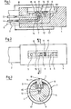
- An essentially cylindrical spray head 1 is attached to the mandrel 2 of a known but not shown machine for producing the weld seam on can bodies 17.
- a slot-shaped spray chamber 3 with a powder line 4 opening into the bottom thereof, one or more suction lines 5 and a high-voltage electrode 6.
- a diaphragm 8 with a bore 9 is slidably fitted over the outlet opening 7 of the powder line 4.
- an eccentric disk 11 is rotatably mounted in the spray head 1, with which the diaphragm 8 can be aligned in a longitudinally displaceable manner via the outlet opening 7 in the spray chamber 3.
- a cross-sectional widening 12 is provided in the area of approximately 5-10 mm below the screen 8.
- the cross section of the extension 12 is approximately 1.5 to 3 times, preferably 2 times the cross section of the powder line 4.
- a connecting channel either leads into the spray chamber 3 or directly into the suction line 5.
- the connecting channel can be designed as a bore 14 (shown in broken lines) or as a groove 15 on the underside of the panel 8.
- the cross section of the connecting channel is generally less than 25% of the cross section of the powder line 4.
- the weld seam 18 of the can body 17 located in the upper apex is located above the spray chamber 3.
- the bore 9 in the diaphragm 8 can have a circular or a slot-shaped cross section (slot-shaped design not shown).
- the spray chamber 3 directed upwards in FIGS. 1 and 3 can also be directed downwards if the weld seams on the spray chamber 3 guided can bodies 17 lie below. None changes in the way it works.
Landscapes
- Nozzles (AREA)
- Electrostatic Spraying Apparatus (AREA)
- Application Of Or Painting With Fluid Materials (AREA)
Description
- Die vorliegende Erfindung betrifft einen Sprühkopf gemäss Oberbegriff des Patentanspruches 1.
- Das Beschichten der geschweissten Längsnähte von Dosenrümpfen mit elektrostatisch aufgeladenem Pulver ist bekannt und findet vorwiegend Verwendung an Dosenrümpfen, in welche empfindliche Füllgüter abgefüllt werden. Als Pulver werden häufig Polymerharze, z.B. Epoxy, Polyethylen, u.a., benutzt, die in feinster Auflösung in einem Luftstrom zur Schweissnaht gefördert und kurz vor dem Auftreffen auf die Naht elektrostatisch aufgeladen werden.
- In der den Oberbegriff des Anspruchs 1 bildenden EP-A-0 093 083 wird ein Pulver/Luft-Gemisch direkt durch eine im wesentlichen senkrecht zur Schweissnaht mündende Leitung auf die Naht ausgestossen.
- Die Verteilung des Pulvers, das infolge seiner Masse am ausseren Radius des Bogens vor der Mündung entlanggleitet, erfolgt entsprechend der Querschnittsform der Leitung im Bogen und an der Mündung. Die Transportluft verlasst die Leitung parallel zum Pulver und gelangt auf der durch die Lage der Leitung gegebenen Bahn zur Schweissnaht.
- Die Aufgaben der Erfindung bestehen nun darin, dem Pulverstrom eine günstige, den Erfordernissen angepasste Querschnittsform und einstellbare Richtung zu geben und mit möglichst wenig Transportluft aus der Mündung auszustossen.
- Nach der Erfindung werden diese Aufgaben gemäss den kennzeichnenden Merkmalen des Patentanspruches 1 gelöst. Weitere vorteilhafte Ausführungsformen sind in den abhängigen Ansprüchen beschrieben.
- In überraschender Weise können mit der den Austrittsquerschnitt der Pulverleitung verändernden Blende sowohl die Flugbahn als auch die Verteilung der Pulverpartikel in der Flugbahn den Erfordernissen der zu lackierenden Schweissnaht entsprechend beeinflusst werden. Durch die Querschnittserweiterung der Pulverleitung vor der Blende kann das Pulver teilweise von der Transportluft getrennt werden, bevor dieses in den Sprühraum eintritt. Die Verbindung der Querschnittserweiterung mit einem Raum, in dem ein niedrigerer Druck als in der Querschnittserweiterung herrscht, ermöglicht den Abfluss der ausgeschiedenen Luft und eine Expansion der in der Pulverleitung zusammengedrängten Pulverpartikel. Ein Anschluss an eine Absaugleitung ermöglicht eine nahezu vollständige Trennung von Pulver und Transportluft vor dem Austritt in den Sprühraum.
- Anhand eines illustrierten Ausführungsbeispieles wird die Erfindung näher erläutert. Es zeigen:
- Figur 1 einen Längsschnitt durch einen Sprühkopf,
- Figur 2 eine Aufsicht auf den Sprühkopf gemäss Figur 1, jedoch ohne Dosenrumpf,
- Figur 3 einen Querschnitt durch den Sprühkopf längs Linie 111-111 in Figur 2.
- Ein im wesentlichen zylinderförmig ausgebildeter Sprühkopf 1 ist am Dorn 2 einer bekannten, jedoch nicht dargestellten Maschine zur Herstellung der Schweissnaht an Dosenrümpfen 17 befestigt.
- Im zentralen, obenliegenden Bereich des Sprühkopfes 1 ist ein schlitzförmiger Sprühraum 3 mit einer an dessen Boden in diesen einmündenden Pulverleitung 4, einer oder mehrerer Absaugleitungen 5 sowie einer Hochspannungselektrode 6 angebracht. Ueber der Austrittsöffnung 7 der Pulverleitung 4 ist eine Blende 8 mit einer Bohrung 9 verschiebbar aufgesetzt. In einer schlitzförmigen Ausnehmung 10 in der Blende 8 ist eine im Sprühkopf 1 drehbar gelagerte Exzenterscheibe 11 eingesetzt, mit der die Blende 8 über der Austrittsöffnung 7 im Sprühraum 3 längsverschiebbar ausgerichtet werden kann.
- Am Ende der Pulverleitung 4 ist im Bereich von ca. 5 - 10 mm unter der Blende 8 eine Querschnittserweiterung 12 angebracht.
- Der Querschnitt der Erweiterung 12 betragt ca. das 1,5- bis 3-fache, vorzugsweise das 2-fache des Querschnittes der Pulverleitung 4. Vom Ende der Pulverleitung 4 bzw. von der Querschnittserweiterung 12 führt ein Verbindungskanal entweder in den Sprühraum 3 oder direkt in die Absaugleitung 5. Der Verbindungskanal kann als Bohrung 14 (in gebrochenen Linien dargestellt) oder als Nut 15 an der Unterseite der Blende 8 ausgebildet sein. Der Querschnitt des Verbindungskanals beträgt in der Regel weniger als 25 % des Querschnittes der Pulverleitung 4. Die im oberen Scheitel liegende Schweissnaht 18 des Dosenrumpfes 17 befindet sich über dem Sprühraum 3.
- Die Bohrung 9 in der Blende 8 kann einen kreisförmigen oder einen schlitzförmigen Querschnitt aufweisen (schlitzförmige Ausführung nicht dargestellt).
- Beim Verschieben der Blende 8 aus einer anfänglich konzentrischen Lage zur Austrittsöffnung 7 der Pulverleitung 4 in eine exzentrische wird ein Teil der Austrittsöffnung 7 abgedeckt, wodurch der Pulverstrom 16 eine Ablenkung, in Figur 1 eine Ablenkung nach rechts, erfährt. Ist das Ende der Pulverleitung 4 mit einem Raum verbunden, in dem ein niedriger Druck als in der Pulverleitung 4 herrscht, so kann ein wesentlicher Teil der unter Überdruck stehenden Speise- oder Trägerluft des Pulvers während der Entspannung in der Querschnittserweiterung 12 ausgeschieden werden. ner Pulverstrom 16 tritt dann als fast reiner Festkörperstrom durch die Blende 8 in den Sprühraum 3 aus und bewegt sich auf die Schweissnaht 18 zu.
- Selbstverständlich kann der in den Figuren 1 und 3 nach oben gerichtete Sprühraum 3 auch nach unten gerichtet werden, falls die Schweissnähte der am Sprühraum 3 vorbeigeführten Dosenrümpfe 17 unten liegen. An der Funktionsweise ändert sich dabei nichts.
Claims (10)
Priority Applications (1)
| Application Number | Priority Date | Filing Date | Title |
|---|---|---|---|
| AT85810036T ATE28411T1 (de) | 1984-02-10 | 1985-02-04 | Spruehkopf einer pulverauftragsvorrichtung. |
Applications Claiming Priority (2)
| Application Number | Priority Date | Filing Date | Title |
|---|---|---|---|
| CH641/84 | 1984-02-10 | ||
| CH641/84A CH648496A5 (de) | 1984-02-10 | 1984-02-10 | Spruehkopf einer pulverauftragsvorrichtung. |
Publications (3)
| Publication Number | Publication Date |
|---|---|
| EP0152375A2 EP0152375A2 (de) | 1985-08-21 |
| EP0152375A3 EP0152375A3 (en) | 1986-06-11 |
| EP0152375B1 true EP0152375B1 (de) | 1987-07-22 |
Family
ID=4191745
Family Applications (1)
| Application Number | Title | Priority Date | Filing Date |
|---|---|---|---|
| EP85810036A Expired EP0152375B1 (de) | 1984-02-10 | 1985-02-04 | Sprühkopf einer Pulverauftragsvorrichtung |
Country Status (4)
| Country | Link |
|---|---|
| EP (1) | EP0152375B1 (de) |
| AT (1) | ATE28411T1 (de) |
| CH (1) | CH648496A5 (de) |
| DE (1) | DE3560349D1 (de) |
Families Citing this family (3)
| Publication number | Priority date | Publication date | Assignee | Title |
|---|---|---|---|---|
| CH663910A5 (de) * | 1985-02-21 | 1988-01-29 | Praezisions Werkzeuge Ag | Beschichtungsanordnungen sowie deren verwendung. |
| IT206322Z2 (it) * | 1985-09-24 | 1987-08-10 | Azzimonti Giovanni Mec Srl | Dispositivo di regolazione della mandata d'aria in una pistola a spruzzo. |
| DE102023003358A1 (de) | 2023-08-12 | 2025-02-13 | Mercedes-Benz Group AG | Vorrichtung zum Besprühen einer Innenwandung eines Hohlraumes |
Family Cites Families (3)
| Publication number | Priority date | Publication date | Assignee | Title |
|---|---|---|---|---|
| CH125657A (de) * | 1927-03-28 | 1928-05-01 | Badische Maschf Gmbh | Pressluftschleudervorrichtung für Beton, Mörtel, Sand und ähnliche Stoffe. |
| GB951589A (en) * | 1959-12-01 | 1964-03-04 | Pyrene Co Ltd | Improvements relating to spraying devices |
| DE3368210D1 (en) * | 1982-04-27 | 1987-01-22 | Siegfried Frei | Process for applying powder in strip form and powder application device |
-
1984
- 1984-02-10 CH CH641/84A patent/CH648496A5/de not_active IP Right Cessation
-
1985
- 1985-02-04 AT AT85810036T patent/ATE28411T1/de not_active IP Right Cessation
- 1985-02-04 DE DE8585810036T patent/DE3560349D1/de not_active Expired
- 1985-02-04 EP EP85810036A patent/EP0152375B1/de not_active Expired
Also Published As
| Publication number | Publication date |
|---|---|
| EP0152375A2 (de) | 1985-08-21 |
| DE3560349D1 (en) | 1987-08-27 |
| CH648496A5 (de) | 1985-03-29 |
| EP0152375A3 (en) | 1986-06-11 |
| ATE28411T1 (de) | 1987-08-15 |
Similar Documents
| Publication | Publication Date | Title |
|---|---|---|
| DE69420186T3 (de) | Vernebler | |
| DE69419084T2 (de) | Apparat zum Aufbringen eines Pulvers sowie zur Herstellung eines Pulverstromes | |
| DE2549974A1 (de) | Vorrichtung zum zerstaeuben von fliessfaehigen medien wie z.b. farben, lacken u.dgl. | |
| DE3501145A1 (de) | Stroemungsverstaerkende fluessigkeitszerstaeubungsduese | |
| DE1667217A1 (de) | Vorrichtung zum Granulieren fliessfaehiger Massen im Fliessbett | |
| DE69928377T2 (de) | Pulverzuführungssystem | |
| EP0913203B1 (de) | Verfahren und Vorrichtung zum Pulver-Sprühbeschichten | |
| DE3420325C2 (de) | ||
| DE1475160B2 (de) | Druckgaszerstäuber zum Versprühen von Flüssigkeiten | |
| EP0763385B1 (de) | Verfahren zur Förderung eines pulverförmigen Gutes mittels eines Injectors | |
| DE931557C (de) | Vorrichtung zum Einbringen von in einem Sammelbehaelter enthaltenen gleichartigen Werkstuecken in einen Profilkanal | |
| EP0913204A1 (de) | Verfahren und Vorrichtung zum Pulver-Sprühbeschichten | |
| DE2237717C3 (de) | Mit Druckmittel betriebene Sprühpistole, z.B. Farbsprühpistole | |
| EP0152375A2 (de) | Sprühkopf einer Pulverauftragsvorrichtung | |
| DE2048043C3 (de) | Sprühvorrichtung | |
| DE2720458A1 (de) | Duese zum verspruehen von fluessigprodukten | |
| DE3329880A1 (de) | Verfahren zum spritzbeschichten ohne luft und spritzpistole fuer das beschichten ohne luft | |
| DE3546231A1 (de) | Pulver-spruehpistole | |
| DE2632795A1 (de) | Ablaufeinrichtung an behaeltern fuer koernige und/oder pulverfoermige materialien (schuettgut) | |
| DE69305651T2 (de) | Lineare zerstäubungsvorrichtung für flüssigkeiten, insbesondere für kühlflüssigkeiten | |
| DE3007990C2 (de) | ||
| DE102017118867A1 (de) | Verladekopf eines pneumatischen Verladesystems für Schüttgüter | |
| DE4041810C2 (de) | Mehrdraht-Lichtbogen-Spritzpistole | |
| EP1054738B1 (de) | Nebelgeneratorkopf | |
| DE519435C (de) | Verfahren zur Herstellung von Lot- oder Schweissdraht |
Legal Events
| Date | Code | Title | Description |
|---|---|---|---|
| PUAI | Public reference made under article 153(3) epc to a published international application that has entered the european phase |
Free format text: ORIGINAL CODE: 0009012 |
|
| AK | Designated contracting states |
Designated state(s): AT BE CH DE FR GB IT LI LU NL SE |
|
| PUAL | Search report despatched |
Free format text: ORIGINAL CODE: 0009013 |
|
| AK | Designated contracting states |
Kind code of ref document: A3 Designated state(s): AT BE CH DE FR GB IT LI LU NL SE |
|
| 17P | Request for examination filed |
Effective date: 19860716 |
|
| 17Q | First examination report despatched |
Effective date: 19861215 |
|
| GRAA | (expected) grant |
Free format text: ORIGINAL CODE: 0009210 |
|
| AK | Designated contracting states |
Kind code of ref document: B1 Designated state(s): AT BE CH DE FR GB IT LI LU NL SE |
|
| PG25 | Lapsed in a contracting state [announced via postgrant information from national office to epo] |
Ref country code: IT Free format text: LAPSE BECAUSE OF FAILURE TO SUBMIT A TRANSLATION OF THE DESCRIPTION OR TO PAY THE FEE WITHIN THE PRESCRIBED TIME-LIMIT;WARNING: LAPSES OF ITALIAN PATENTS WITH EFFECTIVE DATE BEFORE 2007 MAY HAVE OCCURRED AT ANY TIME BEFORE 2007. THE CORRECT EFFECTIVE DATE MAY BE DIFFERENT FROM THE ONE RECORDED. Effective date: 19870722 Ref country code: NL Effective date: 19870722 Ref country code: BE Effective date: 19870722 |
|
| REF | Corresponds to: |
Ref document number: 28411 Country of ref document: AT Date of ref document: 19870815 Kind code of ref document: T |
|
| PG25 | Lapsed in a contracting state [announced via postgrant information from national office to epo] |
Ref country code: SE Effective date: 19870731 |
|
| REF | Corresponds to: |
Ref document number: 3560349 Country of ref document: DE Date of ref document: 19870827 |
|
| ET | Fr: translation filed | ||
| NLV1 | Nl: lapsed or annulled due to failure to fulfill the requirements of art. 29p and 29m of the patents act | ||
| PG25 | Lapsed in a contracting state [announced via postgrant information from national office to epo] |
Ref country code: AT Effective date: 19880204 |
|
| PG25 | Lapsed in a contracting state [announced via postgrant information from national office to epo] |
Ref country code: LU Free format text: LAPSE BECAUSE OF NON-PAYMENT OF DUE FEES Effective date: 19880229 |
|
| PLBE | No opposition filed within time limit |
Free format text: ORIGINAL CODE: 0009261 |
|
| STAA | Information on the status of an ep patent application or granted ep patent |
Free format text: STATUS: NO OPPOSITION FILED WITHIN TIME LIMIT |
|
| 26N | No opposition filed | ||
| PGFP | Annual fee paid to national office [announced via postgrant information from national office to epo] |
Ref country code: GB Payment date: 19950126 Year of fee payment: 11 |
|
| PGFP | Annual fee paid to national office [announced via postgrant information from national office to epo] |
Ref country code: FR Payment date: 19950202 Year of fee payment: 11 |
|
| PGFP | Annual fee paid to national office [announced via postgrant information from national office to epo] |
Ref country code: CH Payment date: 19950220 Year of fee payment: 11 |
|
| PGFP | Annual fee paid to national office [announced via postgrant information from national office to epo] |
Ref country code: DE Payment date: 19950324 Year of fee payment: 11 |
|
| PG25 | Lapsed in a contracting state [announced via postgrant information from national office to epo] |
Ref country code: GB Effective date: 19960204 |
|
| PG25 | Lapsed in a contracting state [announced via postgrant information from national office to epo] |
Ref country code: CH Free format text: LAPSE BECAUSE OF NON-PAYMENT OF DUE FEES Effective date: 19960228 Ref country code: LI Free format text: LAPSE BECAUSE OF NON-PAYMENT OF DUE FEES Effective date: 19960228 |
|
| GBPC | Gb: european patent ceased through non-payment of renewal fee |
Effective date: 19960204 |
|
| REG | Reference to a national code |
Ref country code: CH Ref legal event code: PL |
|
| PG25 | Lapsed in a contracting state [announced via postgrant information from national office to epo] |
Ref country code: FR Effective date: 19961031 |
|
| PG25 | Lapsed in a contracting state [announced via postgrant information from national office to epo] |
Ref country code: DE Effective date: 19961101 |
|
| REG | Reference to a national code |
Ref country code: FR Ref legal event code: ST |