EP0152388A2 - Verfahren und Gerät zum Messen des Durchflusses von fliessfähigen Materialien - Google Patents
Verfahren und Gerät zum Messen des Durchflusses von fliessfähigen Materialien Download PDFInfo
- Publication number
- EP0152388A2 EP0152388A2 EP85850046A EP85850046A EP0152388A2 EP 0152388 A2 EP0152388 A2 EP 0152388A2 EP 85850046 A EP85850046 A EP 85850046A EP 85850046 A EP85850046 A EP 85850046A EP 0152388 A2 EP0152388 A2 EP 0152388A2
- Authority
- EP
- European Patent Office
- Prior art keywords
- sensing means
- flow
- providing
- sensors
- electrically resistive
- Prior art date
- Legal status (The legal status is an assumption and is not a legal conclusion. Google has not performed a legal analysis and makes no representation as to the accuracy of the status listed.)
- Withdrawn
Links
Images

Classifications
-
- G—PHYSICS
- G01—MEASURING; TESTING
- G01F—MEASURING VOLUME, VOLUME FLOW, MASS FLOW OR LIQUID LEVEL; METERING BY VOLUME
- G01F1/00—Measuring the volume flow or mass flow of fluid or fluent solid material wherein the fluid passes through a meter in a continuous flow
- G01F1/05—Measuring the volume flow or mass flow of fluid or fluent solid material wherein the fluid passes through a meter in a continuous flow by using mechanical effects
- G01F1/20—Measuring the volume flow or mass flow of fluid or fluent solid material wherein the fluid passes through a meter in a continuous flow by using mechanical effects by detection of dynamic effects of the flow
- G01F1/28—Measuring the volume flow or mass flow of fluid or fluent solid material wherein the fluid passes through a meter in a continuous flow by using mechanical effects by detection of dynamic effects of the flow by drag-force, e.g. vane type or impact flowmeter
- G01F1/30—Measuring the volume flow or mass flow of fluid or fluent solid material wherein the fluid passes through a meter in a continuous flow by using mechanical effects by detection of dynamic effects of the flow by drag-force, e.g. vane type or impact flowmeter for fluent solid material
-
- G—PHYSICS
- G01—MEASURING; TESTING
- G01F—MEASURING VOLUME, VOLUME FLOW, MASS FLOW OR LIQUID LEVEL; METERING BY VOLUME
- G01F1/00—Measuring the volume flow or mass flow of fluid or fluent solid material wherein the fluid passes through a meter in a continuous flow
- G01F1/05—Measuring the volume flow or mass flow of fluid or fluent solid material wherein the fluid passes through a meter in a continuous flow by using mechanical effects
- G01F1/20—Measuring the volume flow or mass flow of fluid or fluent solid material wherein the fluid passes through a meter in a continuous flow by using mechanical effects by detection of dynamic effects of the flow
- G01F1/206—Measuring pressure, force or momentum of a fluid flow which is forced to change its direction
Definitions
- flowable material as used herein includes liquids and granular or powdered solid material, being material which can, for example, be transported in pipelines by means of screws, pumps, etc.
- the "flowable material” may be, for example, cereal grains, pellets of plastics stock as supplied to manufacturers of plastics products and all types of pumpable liquids.
- a method of measuring the flow rote of a flowable material is charaierised in that the material is caused to meet a flow-measuring surface at an angle, said surface being preferably inclined in relation to the horizontal plane, and in that on inertial force proportional to the flow rate and acting on the surface is sensed by means of sensors emitting an output signal dependant on the flow rate.
- a deflection or shearing stress caused by the inertial force acting on the surface is sensed.
- the inertial force is directly proportional to the quantity of flowing material and by utilising electrical sensors an output signal is obtained which can be converted by simple, conventional means to a readable signal or control signal.
- piezoresistive elements are used to sense the deflection caused by the inertial force, thus enabling even very small variations to be registered.
- apparatus for performing the method is characterised by a flow-measuring surface arranged at an angle to the direction of flow of the flowing material, sensors being provided for sensing the inertial force which the flowing material exerts on the flow-measuring surface, said sensors being arranged to emit a signal which can then be converted to a standard signal proportional to the flow.
- the deflection caused by the inertial force, or the shearing stress caused thereby in the element providing the flow-measuring surface, or a member supporting the element providing said flow-measuring surface is preferably sensed by electrically resistive elements which, in embodiments of the invention, may be arranged on the upper or lower side, or on each side of the element or its supporting member and may be arranged ot an angle to each other, so that an output signal is obtained which is directly propor- fional to tile force acting on the flow-measuring surface.
- the resistive elements consist of piezoresistive elements which have the great advantage of giving signals which can be registered even for extremely slight movements and extremely small fluctuations in the quantity of material coming into contact with the flow-measuring surface can therefore be detected.
- the piezoresistive elements can be built into a ready-made unit or detector which may be attached by two screws, or in similar manner at two spaced-apart points, to the element providing the flow-measuring surface or to the supporting member carrying the element providing the flow-measuring surface.
- the ready-made unit or detector can also include components providing a directly usable output signal.
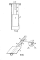
- Figure I shows a feed facility for discharging flowable material, such as plastics pellets, from a store 1.
- the pellets are conveyed horizontally from store I by means of a feed-screw operating in a housing 2.
- the material is fed by the screw into a downcomer 3 and falls from there in a pipe 4 in which a flow transducer, generally designated 5, is fitted.
- the pipe 4 is inclined substantially relative to the horizontal, and the transducer 5 includes a flat plate 7 extending along the axis of the pipe 4, and thus similarly inclined to the horizontal, the upper surface of the plate 7, facing towards the outlet of downcomer 3, constituting the "flow-measuring surface" referred to herein.
- the downcomer 3 is designed so that all the discharged material must be deflected around the corner 6 formed at the lower junction of the downcomer 3 with the upper wall of the pipe 4 and will therefore, irrespective of the quantity, fall substantially vertically from the corner, meeting the flow-measuring surface within a certain predetermined area. As will be explained below, this is of significance for the accuracy of measurement.
- the flow transducer 5 itself, as shown in more detail in Figure 2, consists of a relatively narrow beam 8 supporting the plate 7 at its lower end and fixed at its upper end to a cap fixed to the upper end of the pipe 4.
- a detector module 9 is secured to the lower side of the beam 8, i.e. to the side which faces away from the outlet from the downcomer 3.
- the detector module 9 is in the form of a separately formed unit incorporating piezoresistive elements, said detector module 9 being connected to a central unit, not described in detail, via a cable 10. Signal input and conversion are achieved in conventional manner and do not affect the concept of the invention.
- the module 9 is preferably secured to the beam 8, at two spaced-apart points therealong, by two screws (not shown) or other fasteners.
- Figure 3 shows schematically an alternative embodiment in which a plate 11, providing, by its upper surface, a flow-measuring surface, is mounted on a supporting beam 12 at one end of the beam.
- the beam 12 is in the form of a tube of square cross-section having an upper face, to which plate I is secured, a lower face and opposite vertical side faces 15, 16.
- Sensors 13, 14, which may consist of piezoresistive elements, are arranged on the side faces 15, 16 of the beam 12.
- the elements 13, 14 are elongate and are adapted to sense stresses in directions along their length.
- the two elements 13, 14 are arranged with their axes extending in mutually perpendicular directions and at 45° to the upper and lower faces of the beam 12.
- the two elements 13 and 14 are connected in respective arms of on electrical bridge circuit, the bridge producing a signal, due to the shearing sfresses occurring in the beam, coused by the inertial force exerted by the flowing material on the flow-meosuring surface.
- the material may land substantially anywhere on the measuring surface, without the output signal being affected.
- the difference between the extension and compression occurring respectively on the upper or lower faces of the beam 12 may be measured by arranging appropriate electrical sensors on said upper or lower faces, connecting these sensors in an electrical bridge circuit and using the output signal from the bridge, which is a measurement of said difference, as an indication of the flow rate.
- a plate measuring 66 x 244cm was placed at an angle of 45° to the horizontal plane. This angle was varied within certain limits, as indicated in the table.
- a transducer containing piezoresistive elements was fitted to the lower side of the plate at its upper end.
- the upper surface of the plate, coming into contact with the material of which the flow rate was to be sensed was covered with "TEFLON" (P.T.F.E.) to give the least possible friction between plate and flowing material since this might cause measuring errors.
- the material was allowed to fall vertically down onto the inclined plate fro n various heights and the distance between the contact surface and the edge of the plate located furthest from the transducer was also varied.
- the table indicates the effect of the varying parameters on the output signal, expressed as a percentage.
- a flow measuring apparatus embodying the invention may be used for flow rates within a range of 50 - 1000 kg/h.
Landscapes
- Physics & Mathematics (AREA)
- Fluid Mechanics (AREA)
- General Physics & Mathematics (AREA)
- Measuring Volume Flow (AREA)
- Indicating Or Recording The Presence, Absence, Or Direction Of Movement (AREA)
Applications Claiming Priority (2)
| Application Number | Priority Date | Filing Date | Title |
|---|---|---|---|
| SE8400830A SE8400830L (sv) | 1984-02-16 | 1984-02-16 | Sett och anordning for metning av materialfloden |
| SE8400830 | 1984-02-16 |
Publications (2)
| Publication Number | Publication Date |
|---|---|
| EP0152388A2 true EP0152388A2 (de) | 1985-08-21 |
| EP0152388A3 EP0152388A3 (de) | 1987-01-28 |
Family
ID=20354768
Family Applications (1)
| Application Number | Title | Priority Date | Filing Date |
|---|---|---|---|
| EP85850046A Withdrawn EP0152388A3 (de) | 1984-02-16 | 1985-02-08 | Verfahren und Gerät zum Messen des Durchflusses von fliessfähigen Materialien |
Country Status (2)
| Country | Link |
|---|---|
| EP (1) | EP0152388A3 (de) |
| SE (1) | SE8400830L (de) |
Cited By (4)
| Publication number | Priority date | Publication date | Assignee | Title |
|---|---|---|---|---|
| EP0293104A1 (de) * | 1987-05-13 | 1988-11-30 | Milltronics Ltd. | Durchflussmengenmesser |
| GB2229279A (en) * | 1989-02-20 | 1990-09-19 | Truetzschler & Co | Monitoring a fibre-flock stream |
| WO2014030994A1 (en) | 2012-08-22 | 2014-02-27 | Lely Patent N.V. | Feeding apparatus for supplying feed to a trough and a method of monitoring the functioning of such a feeding apparatus |
| WO2021160282A1 (en) * | 2020-02-14 | 2021-08-19 | Sidel Participations | Flow switch and flow switching method |
Family Cites Families (4)
| Publication number | Priority date | Publication date | Assignee | Title |
|---|---|---|---|---|
| GB1460587A (en) * | 1973-04-27 | 1977-01-06 | Pa Management Consult | Weighing apparatus |
| FR2396957A1 (fr) * | 1977-07-04 | 1979-02-02 | Hasler Freres | Procede de mesure des debits de matieres pulverulentes ou granuleuses et appareil pour sa mise en oeuvre |
| DE2908573A1 (de) * | 1978-03-07 | 1979-09-20 | Federal Ind Ind Group Inc | Durchflussmengenmesser |
| CA1155879A (en) * | 1980-06-17 | 1983-10-25 | David I. M. Elder | Weighing device for fluent material |
-
1984
- 1984-02-16 SE SE8400830A patent/SE8400830L/ unknown
-
1985
- 1985-02-08 EP EP85850046A patent/EP0152388A3/de not_active Withdrawn
Cited By (7)
| Publication number | Priority date | Publication date | Assignee | Title |
|---|---|---|---|---|
| EP0293104A1 (de) * | 1987-05-13 | 1988-11-30 | Milltronics Ltd. | Durchflussmengenmesser |
| GB2229279A (en) * | 1989-02-20 | 1990-09-19 | Truetzschler & Co | Monitoring a fibre-flock stream |
| US5159840A (en) * | 1989-02-20 | 1992-11-03 | Truzschler GmbH & Co. KG | Method and apparatus for measuring, regulating and controlling the quantity of fiber tufts in flight |
| GB2229279B (en) * | 1989-02-20 | 1993-01-20 | Truetzschler Gmbh & Co Kg | Method and apparatus for monitoring a fibre-flock stream |
| WO2014030994A1 (en) | 2012-08-22 | 2014-02-27 | Lely Patent N.V. | Feeding apparatus for supplying feed to a trough and a method of monitoring the functioning of such a feeding apparatus |
| US9723815B2 (en) | 2012-08-22 | 2017-08-08 | Lely Patent N.V. | Feeding apparatus for supplying feed to a trough and a method of monitoring the functioning of such a feeding apparatus |
| WO2021160282A1 (en) * | 2020-02-14 | 2021-08-19 | Sidel Participations | Flow switch and flow switching method |
Also Published As
| Publication number | Publication date |
|---|---|
| SE8400830D0 (sv) | 1984-02-16 |
| EP0152388A3 (de) | 1987-01-28 |
| SE8400830L (sv) | 1985-08-17 |
Similar Documents
| Publication | Publication Date | Title |
|---|---|---|
| US3439761A (en) | Strain-gage transducer structures | |
| US4446730A (en) | Specific gravity independent gauging of liquid filled tanks | |
| US4157661A (en) | Flowmeters | |
| US4407380A (en) | Weighing device for fluent material | |
| US20060248961A1 (en) | Flow sensor and fire detection system utilizing same | |
| US8141421B2 (en) | Tank measurement system using multiple sensor elements | |
| US6555765B2 (en) | Method and apparatus for determining the weight of the contents of a vessel | |
| US4569232A (en) | Reaction mass flowmeter | |
| US5734110A (en) | Temperature compensated, easily installed bolt-on strain sensor | |
| JPS6211115A (ja) | 液体測定システム | |
| US4136567A (en) | Pulp density meter | |
| US4582152A (en) | Weighing mechanism | |
| US20240011806A1 (en) | Flow measurement device | |
| US5099124A (en) | Level detecting apparatus | |
| WO2000066979A1 (en) | Force-sensing mass flow meter | |
| US6651516B2 (en) | Inclined plate apparatus for measuring mass flow | |
| JPH0955233A (ja) | 液体の比重、液面高さ及び液温測定装置 | |
| US4561307A (en) | Liquid differential pressure measurement using a vertical manifold | |
| US3698495A (en) | Electrical weight indicating device | |
| KR102121051B1 (ko) | 로드셀 유속계 | |
| US6327916B1 (en) | Apparatus and method for measuring the flow characteristics of a slurry | |
| CN201335723Y (zh) | 一种荷重传感器及皮带秤 | |
| JPH0711439B2 (ja) | 液量測定装置 | |
| EP1272818B1 (de) | Feinpartikel-strömungsmesser | |
| RU2093797C1 (ru) | Способ бесконтактного определения веса изделий из материалов малой удельной плотности и устройство для его осуществления |
Legal Events
| Date | Code | Title | Description |
|---|---|---|---|
| PUAI | Public reference made under article 153(3) epc to a published international application that has entered the european phase |
Free format text: ORIGINAL CODE: 0009012 |
|
| AK | Designated contracting states |
Designated state(s): AT BE CH DE FR GB IT LI LU NL SE |
|
| RAP1 | Party data changed (applicant data changed or rights of an application transferred) |
Owner name: EDAB ELECTRONIC DESIGN AB |
|
| PUAL | Search report despatched |
Free format text: ORIGINAL CODE: 0009013 |
|
| AK | Designated contracting states |
Kind code of ref document: A3 Designated state(s): AT BE CH DE FR GB IT LI LU NL SE |
|
| STAA | Information on the status of an ep patent application or granted ep patent |
Free format text: STATUS: THE APPLICATION IS DEEMED TO BE WITHDRAWN |
|
| 18D | Application deemed to be withdrawn |
Effective date: 19871209 |
|
| RIN1 | Information on inventor provided before grant (corrected) |
Inventor name: VIKTORSSON, OLLE |