EP0152676A2 - Positionsservosystem - Google Patents
Positionsservosystem Download PDFInfo
- Publication number
- EP0152676A2 EP0152676A2 EP84306836A EP84306836A EP0152676A2 EP 0152676 A2 EP0152676 A2 EP 0152676A2 EP 84306836 A EP84306836 A EP 84306836A EP 84306836 A EP84306836 A EP 84306836A EP 0152676 A2 EP0152676 A2 EP 0152676A2
- Authority
- EP
- European Patent Office
- Prior art keywords
- belt
- driven member
- drive
- resonant frequency
- pulley
- Prior art date
- Legal status (The legal status is an assumption and is not a legal conclusion. Google has not performed a legal analysis and makes no representation as to the accuracy of the status listed.)
- Withdrawn
Links
- 230000033001 locomotion Effects 0.000 claims description 12
- 230000008859 change Effects 0.000 claims description 2
- 230000010355 oscillation Effects 0.000 abstract description 4
- 238000010276 construction Methods 0.000 abstract 1
- 230000001939 inductive effect Effects 0.000 abstract 1
- 230000000694 effects Effects 0.000 description 6
- 239000002184 metal Substances 0.000 description 4
- 230000000875 corresponding effect Effects 0.000 description 2
- 238000010586 diagram Methods 0.000 description 2
- 238000006073 displacement reaction Methods 0.000 description 2
- 238000012544 monitoring process Methods 0.000 description 2
- 230000009471 action Effects 0.000 description 1
- 230000008901 benefit Effects 0.000 description 1
- 238000006243 chemical reaction Methods 0.000 description 1
- 230000002596 correlated effect Effects 0.000 description 1
- 230000008878 coupling Effects 0.000 description 1
- 238000010168 coupling process Methods 0.000 description 1
- 238000005859 coupling reaction Methods 0.000 description 1
- 230000008030 elimination Effects 0.000 description 1
- 238000003379 elimination reaction Methods 0.000 description 1
- 230000010358 mechanical oscillation Effects 0.000 description 1
- 230000003287 optical effect Effects 0.000 description 1
- 230000003534 oscillatory effect Effects 0.000 description 1
- 230000004044 response Effects 0.000 description 1
- 230000017702 response to host Effects 0.000 description 1
- 238000000926 separation method Methods 0.000 description 1
- 238000001228 spectrum Methods 0.000 description 1
- 230000003019 stabilising effect Effects 0.000 description 1
Images
Classifications
-
- G—PHYSICS
- G05—CONTROLLING; REGULATING
- G05D—SYSTEMS FOR CONTROLLING OR REGULATING NON-ELECTRIC VARIABLES
- G05D3/00—Control of position or direction
- G05D3/12—Control of position or direction using feedback
- G05D3/14—Control of position or direction using feedback using an analogue comparing device
- G05D3/1409—Control of position or direction using feedback using an analogue comparing device with DC amplifier chain
-
- F—MECHANICAL ENGINEERING; LIGHTING; HEATING; WEAPONS; BLASTING
- F41—WEAPONS
- F41G—WEAPON SIGHTS; AIMING
- F41G3/00—Aiming or laying means
- F41G3/22—Aiming or laying means for vehicle-borne armament, e.g. on aircraft
Definitions
- This invention relates to position servo systems of the type in which a movable driven member is coupled to a positioning drive motor by a drive belt and in particular to the elimination of positional jitter of the driven member.
- a position servo in which a drive motor is rigidly coupled to move a rotatable primary driven member which in turn is coupled by a drive belt to move a secondary driven member to a desired position.
- An electrical feedback control loop between a sensor of the position of the primary driven member and the drive motor maintains, or effects a change in, the position of the primary driven member in terms of a difference between the actual motor position, and a demanded position, determined by an applied signal.
- the operating bandwidth may be relatively low, say 0 - 50Hz, but electrical noise generated within the servo loop at higher frequencies and normally resulting only in minor perturbations of the primary driven member may excite vibrations in the drive belt which may resonate and induce oscillating movement of the secondary driven member with respect to the primary driven member, i.e. jitter, which is outside the control loop of the servo.
- the jitter may be particularly troublesome in precision servo systems where the drive belt effects a step-up linkage (gearing) between the primary and secondary driven members.
- the secondary driven member comprises a pulley, carrying a sighting mirror, to be stabilised by the servo system to within 50 microradians and is coupled by a tensioned metal tape drive belt to a primary driven member pulley of half the diameter (giving a 2 : 1 step up). Resonance induced within the drive tape may cause a sightline jitter of 1 - 2 milliradians.
- a belt-drive position servo system including a drive motor (13) rigidly coupled to a primary driven member (15), a secondary driven member (16) coupled to the primary driven member by a flexible drive belt (17) to be positioned thereby and an electrical feedback control loop between a sensor (18) of the position of the primary driven member and the drive motor is characterised in that the flexible belt is maintained with a tension therein such that the resonant frequency of along-axis vibrations in the belt is displaced from the resonant frequency of the servo system and in that the feedback control loop includes notch filter means (20) operable to attenuate signals in the feedback control loop in a frequency band including the resonant frequency of along-axis vibrations of the drive belt.
- the present invention thus results in a position servo system which has the advantage of retaining a feedback control loop requiring only monitoring of the position of the primary driven member and avoids the complexity which would be associated with monitoring the secondary driven member and accommodating signals due to additional motions thereof in the feedback control loop.
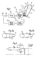
- a servo system 10 is employed to maintain the angular position of a sighting mirror 11 about an axis 12, the axis being fixed in relation to a gyro stabilised platform carried by a vehicle.
- the vehicle, platform and means for stabilising its orientation with respect to movements of the vehicle form no part of the invention and are not shown.
- the platform carries, fixed in relation thereto, a drive motor 13 having a rotatable drive shaft 14 on which is mounted a primary driven member 15 in the form of a pulley.
- the axis of rotation of the drive shaft 14 and the mirror 12 are parallel and the mirror carries a secondary driven member 16, also in the form of a pulley, coupled to the primary driven member by a drive belt 17 by which the secondary driven member and mirror can be rotated about the axis 12.
- the drive belt 17 is in the form of a metal tape held in tension by adjustable clamping means 25 to fix the axle positions, and thus the separation, of the two driven members. Where the axis 12 is part of an optical path it is preferable to make adjustment to the primary driven member 15, such as by way of its drive shaft 14 as shown.
- the secondary driven member 16 is twice the diameter of the primary driven member giving a step-up 'gearing' of 2 : 1.
- the motor shaft 14 is coupled to a shaft angle position sensor 18 which for precisely representing angular displacement is formed by a rate integrating gyro.
- An output signal of the sensor representing angular position is fed by way of a phase advance means 19 to band attenuation, or notch filter, means 20, described in detail hereinafter with reference to Figure 3, and thence to an amplifier 21.
- the output of amplifier 21 provides drive to the drive motor 13.
- the rotational position of the secondary driven member is a function of a position demand signal fed into the servo loop, either at a second input 22 to amplifier 21, where the difference between it and the feedback signal forms an error signal, or by applying a torquing signal at 23 to the sensor gyro.
- the notch filter means 20 is 'transparent' as will be explained hereinafter and the system behaves as a simple known position feedback servo system.
- the principle source of such relative movement is vibration of the drive belt and although such vibrations are generally small at certain frequencies resonance occurs and the amplified vibrations induce a corresponding vibration or positional jitter in the secondary driven member.
- the first mode of vibration is transversely to the longitudinal axis of the belt and illustrated in Figure 2(a).
- the frequency of resonant vibration can be calaculated as described in the text books for any simple vibrating string arrangement.
- the second mode of vibration is along the longitudinal axis of the belt as illustrated in Figure 2(b), the belt acting as a stiff spring.
- the first and, sometimes second, mode of vibration may be caused by vibration of the host vehicle or like mechanical forces and where such vibrations exist at a resonant frequency of the belt such resonant vibration may be eliminated by changing the tension within the belt.
- the second mode of vibration may, however, be induced as a result of electrical noise within the servo system.
- Such noise provides a small error signal to the motor which displaces the primary driven member accordinly, whereupon the sensor reacts and its signal may be modified by the noise to apply a restoring signal to the motor.
- oscillating motion of the primary driven member acting along the drive belt can cause such oscillation to increase in amplitude until the reaction on the primary driven member generates a correlated displacement signal from the sensor which reverses the drive direction of motor 12.
- an oscillating motion of the primary driven member and belt may be quickly established, transferring the oscillatory motion to the secondary driven member which causes positional jitter of the scanning mirror 11.
- the tension in the belt is chosen to produce a resonant frequency for along-axis vibrations in the belt greater than the upper limit of the bandwidth of the servo system, as dictated by positioning the secondary driven member, and the notch filter means 20 has a bandwidth chosen to provide an attenuation 'notch' centred on the resonant frequency.
- the notch filter is transparent to feedback signals but any electrical noise generated in the electrical feedback signal at the resonant frequency is blocked before a mechanical oscillation can become established.
- the notch filter means 20 may take any one of a number of known forms and is preferably an active circuit.
- FIG. 3 One example of a notch filter circuit of known form is shown in Figure 3, as published in an article entitled “Active Notch Filter” by Yishay Nezer in Wireless world, July 1975, pages 307-311.
- the circuit comprises an operational amplifier A with passive input and feedback components including two variable resistors VR1 and VR 2 by which the centre frequency of the 'notch' can be tuned.
- Two such notch filters in cascade provides a suitable degree of attenuation and bandwidth for the notch filter means, of the order of 40d8 with a spread of about ⁇ 10Hz [centred at about 350Hzj.
- any suitable filter means incorporating desired design criteria as to notch frequency and width may be employed.
- the notch filter means may be located anywhere in the feedback control loop, that is between sensor 18 and amplifier 21, to attentuate any tendency for signals to build up at the resonant frequency but if the phase advance circuit 19 includes a gain element which would serve to amplify noise signals the notch filter is preferably located as the final element before the motor driving amplifier 21.
- the drive belt 17 is a tensioned metal tape and the sensor 18 a rate integrating gyro.
- Such components in combination with precision pivotal bearings enables a servo system to be constructed offering great positional accuracy to the secondary driven member, say 50 microradians.
- the attenuation, or notch, frequency of the filter means, and the drive belt resonance is chosen to be sufficiently greater than the response bandwidth of the servo system to avoid introducing any instability therein.
- the servo system has a bandwidth of 0 - 50 HZ so that a resonant frequency in excess of about 150Hz is suitable, one value used being approximately 350Hz.
- the adjustable clamping means 25 which effects tensioning of the drive belt may take any convenient form other than the simple screw adjuster. Also the clamping means may be provided with means for measuring the actual tension in the drive belt 17, such as a strain gauge 26 giving a readable indication or corresponding output signal at 27, enabling precise adjustment of the resonant frequency. If operating conditions result in variations in tension and consequential drift of resonant frequency the measured 'tension' output at 27 may be used in a separate closed loop servo 28 to control the clamping means 25 and thus maintain a demanded level of belt tension.
- the senor may be a less sophisticated angle resolving pick-off and the drive belt may be other than a metal tape.
- the system is not limited to use with rotary motion, where the primary and secondary driven members are pulleys, but may for instance be employed where coupling between lineariy displaceable members is effected by a drive belt.
Landscapes
- Engineering & Computer Science (AREA)
- Physics & Mathematics (AREA)
- General Physics & Mathematics (AREA)
- Automation & Control Theory (AREA)
- Aviation & Aerospace Engineering (AREA)
- General Engineering & Computer Science (AREA)
- Control Of Position Or Direction (AREA)
- Gyroscopes (AREA)
- Control Of Electric Motors In General (AREA)
- Feedback Control In General (AREA)
Applications Claiming Priority (2)
| Application Number | Priority Date | Filing Date | Title |
|---|---|---|---|
| GB08327514A GB2155657B (en) | 1983-10-13 | 1983-10-13 | Position servo system |
| GB8327514 | 1983-10-13 |
Publications (2)
| Publication Number | Publication Date |
|---|---|
| EP0152676A2 true EP0152676A2 (de) | 1985-08-28 |
| EP0152676A3 EP0152676A3 (de) | 1986-04-02 |
Family
ID=10550176
Family Applications (1)
| Application Number | Title | Priority Date | Filing Date |
|---|---|---|---|
| EP84306836A Withdrawn EP0152676A3 (de) | 1983-10-13 | 1984-10-08 | Positionsservosystem |
Country Status (4)
| Country | Link |
|---|---|
| US (1) | US4636700A (de) |
| EP (1) | EP0152676A3 (de) |
| JP (1) | JPS60114904A (de) |
| GB (1) | GB2155657B (de) |
Cited By (1)
| Publication number | Priority date | Publication date | Assignee | Title |
|---|---|---|---|---|
| EP0449625A3 (de) * | 1990-03-30 | 1991-10-16 | Tektronix, Inc. | Geschwindigkeitsregler für Massen |
Families Citing this family (12)
| Publication number | Priority date | Publication date | Assignee | Title |
|---|---|---|---|---|
| JPH01304511A (ja) * | 1988-06-02 | 1989-12-08 | Seiko Instr Inc | サーボ制御装置 |
| US4914726A (en) * | 1989-01-17 | 1990-04-03 | Tektronix, Inc. | Mass velocity controller |
| JPH03246195A (ja) * | 1990-02-26 | 1991-11-01 | Teijin Seiki Co Ltd | アクチュエータシステムの安定性補償回路 |
| US5554915A (en) * | 1991-05-13 | 1996-09-10 | Delco Electronics Corporation | High impedance AC coupling method for quick command response in torque compensation systems |
| US5640074A (en) * | 1992-06-19 | 1997-06-17 | Agfa Division, Bayer Corporation | Vibration dampening method and apparatus for band driven precision motion systems |
| US5451852A (en) * | 1993-08-02 | 1995-09-19 | Gusakov; Ignaty | Control system having signal tracking window filters |
| JPH07264712A (ja) * | 1994-03-18 | 1995-10-13 | Hitachi Ltd | 電気車の制御装及び制御方法 |
| US6046560A (en) * | 1998-03-20 | 2000-04-04 | Trw Inc. | Electric assist steering system having an improved motor current controller with gain scheduler |
| US6107767A (en) * | 1998-03-20 | 2000-08-22 | Trw Inc. | Electric assist steering system having an improved motor current controller with notch filter |
| US6560059B1 (en) | 1999-05-07 | 2003-05-06 | Seagate Technology Llc | Method and apparatus for suppressing seek-induced vibration in a disc drive |
| JP2008312339A (ja) * | 2007-06-14 | 2008-12-25 | Panasonic Corp | 電動機の制御装置 |
| WO2021234209A1 (en) * | 2020-05-19 | 2021-11-25 | Kone Corporation | A method and a door drive unit for defining tension of a belt of an automatic door |
Family Cites Families (9)
| Publication number | Priority date | Publication date | Assignee | Title |
|---|---|---|---|---|
| US3493826A (en) * | 1965-09-13 | 1970-02-03 | Honeywell Inc | Servomechanism including a lead network feedback and means to modify the lead network responsive to rate |
| GB1145314A (en) * | 1967-01-05 | 1969-03-12 | Ass Elect Ind | Improvements relating to positional control equipment |
| GB1206720A (en) * | 1968-02-22 | 1970-09-30 | Rank Organisation Ltd | Improvements in servo control systems |
| FR2382020A1 (fr) * | 1977-02-23 | 1978-09-22 | Telecommunications Sa | Dispositif mecanique pour la stabilisation du site d'un systeme de surveillance panoramique |
| FR2425086A1 (fr) * | 1978-05-03 | 1979-11-30 | Telecommunications Sa | Perfectionnements aux systemes optiques de surveillance panoramique |
| JPS5611649A (en) * | 1979-07-10 | 1981-02-05 | Sony Corp | Record player |
| JPS5748545A (en) * | 1980-09-08 | 1982-03-19 | Hitachi Ltd | Sheet conveying apparatus |
| US4387971A (en) * | 1980-09-30 | 1983-06-14 | The United States Of America As Represented By The Secretary Of The Air Force | Dynamic damping system |
| US4439716A (en) * | 1981-12-07 | 1984-03-27 | The Singer Company | Compensation apparatus for an electrohydraulic servovalve |
-
1983
- 1983-10-13 GB GB08327514A patent/GB2155657B/en not_active Expired
-
1984
- 1984-10-08 EP EP84306836A patent/EP0152676A3/de not_active Withdrawn
- 1984-10-11 JP JP59211607A patent/JPS60114904A/ja active Pending
- 1984-10-12 US US06/660,312 patent/US4636700A/en not_active Expired - Fee Related
Cited By (1)
| Publication number | Priority date | Publication date | Assignee | Title |
|---|---|---|---|---|
| EP0449625A3 (de) * | 1990-03-30 | 1991-10-16 | Tektronix, Inc. | Geschwindigkeitsregler für Massen |
Also Published As
| Publication number | Publication date |
|---|---|
| GB2155657A (en) | 1985-09-25 |
| US4636700A (en) | 1987-01-13 |
| GB2155657B (en) | 1987-01-21 |
| JPS60114904A (ja) | 1985-06-21 |
| EP0152676A3 (de) | 1986-04-02 |
Similar Documents
| Publication | Publication Date | Title |
|---|---|---|
| EP0152676A2 (de) | Positionsservosystem | |
| CA1113291A (en) | Optical beam vibrating device | |
| US4393597A (en) | Stabilized sighting devices for vehicles | |
| RU2327109C2 (ru) | Способ компенсирования поперечного смещения в кориолисове гироскопе, а также кориолисов гироскоп, который пригоден для этой цели | |
| US4884446A (en) | Solid state vibrating gyro | |
| EP0504930A1 (de) | Optischer Apparat zur Korrektur de Bildverschiebung | |
| DE19642893A1 (de) | Schwingungskonstruktion | |
| KR100392261B1 (ko) | 타원진동장치 | |
| EP0662626B1 (de) | Lichtablenkvorrichtung mit Detektion der Winkelabweichung | |
| EP0487622B1 (de) | Stabilisierungssystem mit inertia | |
| US3992952A (en) | Control system for angular displacement sensor | |
| EP1316831B1 (de) | Methode und Vorrichtung zum Regeln eines optischen Abtastgeräts | |
| JP3041152B2 (ja) | 像安定化装置 | |
| EP0508421A2 (de) | Zittergerät | |
| US4123136A (en) | Piezo-electric line of sight corrector for inertial platform stabilized sensor in a stellar navigational system | |
| EP3652500B1 (de) | Flüstergaleriemodus-trägheitssensor und verfahren | |
| JPH0161196B2 (de) | ||
| US4387971A (en) | Dynamic damping system | |
| US4062126A (en) | Deadband error reduction in target sight stabilization | |
| US3168833A (en) | Timing escapement mechanism | |
| US3967178A (en) | Wide band angular displacement and velocity sensor and method | |
| US3577646A (en) | Method of damping devices having oscillatory motion | |
| US7304411B2 (en) | Method and apparatus for reducing Q factor in an oscillating laser scanner | |
| US5027047A (en) | Half angle mechanism for a heliostat | |
| US4340271A (en) | Internal body mounted system for isolation of, in one degree of freedom, a beam projected from an optical system which is subject to rotational vibration |
Legal Events
| Date | Code | Title | Description |
|---|---|---|---|
| PUAI | Public reference made under article 153(3) epc to a published international application that has entered the european phase |
Free format text: ORIGINAL CODE: 0009012 |
|
| AK | Designated contracting states |
Designated state(s): DE FR IT NL SE |
|
| PUAL | Search report despatched |
Free format text: ORIGINAL CODE: 0009013 |
|
| AK | Designated contracting states |
Kind code of ref document: A3 Designated state(s): DE FR IT NL SE |
|
| RHK1 | Main classification (correction) |
Ipc: G05D 3/12 |
|
| 17P | Request for examination filed |
Effective date: 19860508 |
|
| 17Q | First examination report despatched |
Effective date: 19880329 |
|
| RAP1 | Party data changed (applicant data changed or rights of an application transferred) |
Owner name: FERRANTI INTERNATIONAL SIGNAL PLC |
|
| STAA | Information on the status of an ep patent application or granted ep patent |
Free format text: STATUS: THE APPLICATION IS DEEMED TO BE WITHDRAWN |
|
| 18D | Application deemed to be withdrawn |
Effective date: 19891010 |
|
| RIN1 | Information on inventor provided before grant (corrected) |
Inventor name: DAVIDSON, JOHN DUNLOP Inventor name: MOORE, PETER GEORGE |