EP0152892A2 - Rotierendes Blatt für landwirtschaftliche Maschine - Google Patents
Rotierendes Blatt für landwirtschaftliche Maschine Download PDFInfo
- Publication number
- EP0152892A2 EP0152892A2 EP85101450A EP85101450A EP0152892A2 EP 0152892 A2 EP0152892 A2 EP 0152892A2 EP 85101450 A EP85101450 A EP 85101450A EP 85101450 A EP85101450 A EP 85101450A EP 0152892 A2 EP0152892 A2 EP 0152892A2
- Authority
- EP
- European Patent Office
- Prior art keywords
- blade
- carrying flange
- flange
- carrying
- secured
- Prior art date
- Legal status (The legal status is an assumption and is not a legal conclusion. Google has not performed a legal analysis and makes no representation as to the accuracy of the status listed.)
- Withdrawn
Links
- 0 C=*1C(F)=C*=C*1 Chemical compound C=*1C(F)=C*=C*1 0.000 description 2
Images



Classifications
-
- A—HUMAN NECESSITIES
- A01—AGRICULTURE; FORESTRY; ANIMAL HUSBANDRY; HUNTING; TRAPPING; FISHING
- A01B—SOIL WORKING IN AGRICULTURE OR FORESTRY; PARTS, DETAILS, OR ACCESSORIES OF AGRICULTURAL MACHINES OR IMPLEMENTS, IN GENERAL
- A01B33/00—Tilling implements with rotary driven tools, e.g. in combination with fertiliser distributors or seeders, with grubbing chains, with sloping axles, with driven discs
- A01B33/08—Tools; Details, e.g. adaptations of transmissions or gearings
- A01B33/14—Attaching the tools to the rotating shaft, e.g. resiliently or flexibly-attached tools
- A01B33/142—Attaching the tools to the rotating shaft, e.g. resiliently or flexibly-attached tools the rotating shaft being oriented horizontally
Definitions
- the invention has for its object an agricultural implement provided with rotary blades which are secured in a changeable manner to at least one blade-carrying flange of a shaft.
- each blade is secured to the respective blade-carrying flange by means of two bolts. Consequently the operation of changing a blade required a fairly long and tiring work, since it was necessary to remove two bolts which, in consideration of their working conditions, cannot be unscrewed easily.
- the blades frequently break and/or get worn rapidly, so that they must be frequently changed, it appears evident that the securing of same onto the blade-carrying flange by means of two bolts causes a considerable loss of time and requires a remarkable work.
- the invention has for its purpose to eliminate the above mentioned inconveniences and to provide an agricultural implement of the aforementioned type in which the blades can be mounted and dismounted and consequently changed more easily and more quickly. Moreover, the invention aims to increase the width of the strip of soil worked by the blades of each blade-carrying flange, by adopting a simple and economical construction of the said blade-carrying flange.
- each blade adhering onto one side of the blade--carrying flange, is secured to same by means of one single locking bolt and it presents a locking shank which passes through a corresponding opening in the blade--carrying flange, and adheres against the other side of same.
- the locking shank of the blade may be constructed in different manners.
- the said locking shank extends in the longitudinal direction of the blade and is crank-shaped so as to get hooked by its end to the edge of the opening provided in the blade-carrying flange and opposite to the blade.
- the locking shank of the blade and the corresponding opening are constructed in such a manner as to realize a bayonet joint.
- the locking shank extends towards the surface of the blade-carrying flange through the opening of same and presents at its end a head consisting of at least one transverse locking tooth which projects out laterally, while the corresponding-opening in the blade-carrying flange presents at least a recess which consents the passage of the said locking tooth but it is angularly offset with respect to the position which this latter assumes when the blade is secured by means of the bolt to the blade-carrying flange.
- the blade is engaged by its locking shank into the corresponding opening of the blade-carrying flange by means of angular movements substantially parallel to the surface of the blade-carrying flange, firstly in order to make the locking tooth of the shank of the blade coincide with the corresponding recess of the opening of the blade--carrying flange and thereafter in order to offset said tooth, after being passed through the opening of the blade-carrying flange, with respect to the enlarged recess of the said opening, so as to engage the said locking tooth with the other side of the said blade-carrying flange.
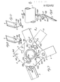
- reference numeral 1 denotes the horizontal tubular shaft of an agricultural implement for working the soil by means of rotary blades. More particularly shaft 1 may be the shaft of a rotary cultivator. Onto shaft 1 there are secured, and more particularly welded, the blade-carrying flanges 2, spaced between one another. To each blade-carrying flange 2 there are secured in a removable manner the blades 3 which are directed substantially radially or tangentially to shaft 1 or at a certain angle with respect to the radial direction, and which project periferally from the respective blade-carrying flange 2.
- Each blade 3 adheres against the respective blade-carrying flange 2 by means of a corresponding flat base portion 103 from which there extends towards the shaft 1 a locking shank 203 consisting of a tapered appendix of the blade 3 itself.
- the said locking shank 203 is crank-shaped and is passed through a corresponding opening 4 in the blade-carrying flange 2, so as to adhere and to get hooked by its end to the edge of the opening 4 opposite to blade 3, that is so as to adhere with said end against the side of the blade--carrying flange which is opposite to the side against which the blade 3 itself adheres.
- the blade 3 is thus hooked by its locking shank 203 to the blade-carrying flange 2 and it is secured to the said flange, at the base portion 103 of the blade 3, by means of one single bolt 5 with respective nut 6 and spring washer 7.
- the locking shank 203 of blade 3 presents longitudinal side edges which are parallel to each other, while the corresponding opening 4 in the blade-carrying flange 2 is substantially rectangular.
- each blade 3 is secured to the respective blade-carrying flange 2 by means of one single bolt 5 and of a locking shank 303 or 403 which is engaged in a corresponding opening 4 obtained in the blade-carrying flange 2.
- the locking shank 303 or 403 of each blade 3 consists of a stem which extends from the blade 3 towards the surface of the blade-carrying flange 2 and passes through a corresponding opening 4 obtained in the said flange.
- the locking shank 303 or 403 presents a head consisting of two transverse locking teeth 503 which are diametrally opposite and projecting laterally, and which adhere against the side of the blade-carrying flange 2 opposite to the side onto which there adheres the respective blade 3.
- the opening of the blade-carrying flange 2, corresponding to the locking shank 303 or 403 of each blade 3, comprises a central portion 4, through which there passes only the stem of the locking shank, and which presents two extensions or recesses 104 diametrally opposed, through which there may pass the lateral locking teeth 503 of the head of the locking shank 303 or 403 itself.
- the said two recesses 104 are however angularly offset with respect to the position which the lateral locking teeth 503 of the locking shank 303 or 403 of the blade 3 assume in the locking position of blade 3 to the blade-carrying flange 2. In this manner, there is obtained a bayonet connection between the locking shank 303 or 403 of blade 3 and the blade-carrying flange 2.
- this latter is kept at an angular position such that the two lateral locking teeth 503 of its locking shank 303 or 403 come to coincide with the corresponding recesses 104 of the opening 4 and can be therefore inserted through said recesses 104 so as to pass to the opposite side of the blade-carrying flange 2, as shown by dash-and-dot lines in Figure 7.
- the blade 3 is rotated by its locking shank 303 or 403 at the interior of opening 4 parallelly to the surface of the blade-carrying flange 2, for example in the direction of arrow F of Figure 7, so as to be brought to its final mounting position, in which the lateral locking teeth 503 of the locking shank 303 or 403 come to be angularly offset with respect to the recessed portions 104 of the opening 4 and get hooked to the edges of said opening 4 on the side of the blade-carrying flange 2 opposite to the blade 3 itself, as shown by full lines in Figure 7.
- the blade 3 is secured to the blade-carrying flange 2 by means of one single bolt 5 with a respective nut 6 in the zone of the base portion 103 of the blade 3 itself.
- the dismounting of the blade 3 is effected in the contrary manner.
- the blades 3 can be made in any suitable manner. Preferably, both longitudinal side edges of the blades are sharpened. Moreover, the active portion of blades 3, which projects peripherally from the blade-carrying flange 2, is slightly bent with respect to the base portion 103 which adheres against the blade-carrying flange 2 and it can be either flat or even curved, as illustrated in the case of blade 3 of Figure 5. The displacement of blades 3 parallelly to the blade--carrying flange 2 around the respective locking bolt 5 is avoided by the abutment of the locking shank 203, 303, 403 of the blade against the side edges of the respective opening 4 in the blade-carrying flange 2.
- each blade 3 may be provided with a projecting portion 603 which bears against the edge of the blade--carrying flange 2, as shown in Figure 1.
- reference numeral 8 indicates the bore in blade 3 for the locking bolt 5
- Figures 6, 7, 11, 12 and 13 reference numerals 9 indicate the bores provided in the blade-carrying flange for the locking bolts 5.
- the blade-carrying flanges 2, onto which the blades 3 are secured in the above mentioned manner, may be constructed in any suitable manner and can be flat and perpendicular to the axis of the respective shaft 1 or inclined with respect to same.
- each blade-carrying flange 2 presents some portions which form different angles with respect to the axis of shaft 1 and carry each at least one blade 3, with the purpose of increasing the width of the strip of soil worked by the blades of a blade-carrying flange.
- each blade--carrying flange 2 (with the exception of the terminal blade-carrying flanges 2" provided at the ends of shaft 1) consists of a square plate, of which two angular portions 102 diagonally opposed are slightly bent in opposite directions with respect to the interposed central portion 202, along two lines 10 which are parallel to each other and to the diagonal corresponding to the other two angles of the plate.
- This blade-carrying flange 2 is secured onto shaft 1 with its median flat and diagonal portion 202 directed perpendicularly to shaft 1 itself.
- the median portion 202 of the blade-carrying flange 2 presents preferably a suitable bore, by means of which it is inserted onto the shaft 1, onto which it is secured by means of welding 11, as shown in Figure 5.
- a blade 3 At each angle of this blade-carrying flange 2 there is mounted a blade 3.
- the blades 3 provided at the two angles of the median portion 202 perpendicular to shaft 1, are arranged on opposite sides of the blade-carrying flange 2.
- the blades 3 provided at the bent angular portions 102 are arranged on opposite sides of the blade-carrying flange 2.
- the width of the soil strip worked by the blades 3 of a blade--carrying flange 2 corresponds substantially to the distance between the circles described by the free ends of the two blades 3 secured to the bent angular portions 2 of the blade-carrying flange 2.
- These blades work the respective marginal zones of the said strip, while the median zone of said strip is worked by the two blades 3 secured at the angles of the diagonal median portion 202 of the blade-carrying flange 2.
- the blades (not shown) are secured to the blade-carrying flange 2' at the angles of same, that is each one on one of the bent angular portions 102'.
- Figures 11 to 13 there are shown just the bores 9 for the locking bolts 5 and the openings 4 for the locking shanks of the blades.
- the central portion 202' of the blade-carrying flange 2' is provided with a bore 13 for mounting the flange 2' onto shaft 1.
- a flat terminal blade-carrying flange 2" which is perpendicular to shaft 1 and is secured to same for example by means of welding 14.
- a reinforcing flange 12 secured to the head end of shaft 1 by means of welding 15.
- This reinforcing flange 12 presents a four-lobed shape or in any case it is provided with recesses for giving space to the openings 4 of the blade-carrying flange 2" for the insertion of the locking shanks 203 of blades 3.
- the reinforcing flange 12 is secured also to the blade--carrying flange 2" by means of welding 16.
- the end of shaft 1 is reinforced by means of an inner tube 18.
- blades 3 are slightly bent with respect to their base portion 103 and. are fixed at the angles of a polygonal blade-carrying flange 2, 2', 2", for example of triangular, square, pentagonal or the like shape
- the corresponding angle portion 302, 302', 302" of the blade-carrying flange 2, 2', 2" is bent in such a manner to result parallel to the blade 3 and to serve as support for said blade.
Landscapes
- Life Sciences & Earth Sciences (AREA)
- Engineering & Computer Science (AREA)
- Mechanical Engineering (AREA)
- Soil Sciences (AREA)
- Environmental Sciences (AREA)
- Soil Working Implements (AREA)
- Threshing Machine Elements (AREA)
- Harvester Elements (AREA)
Applications Claiming Priority (2)
| Application Number | Priority Date | Filing Date | Title |
|---|---|---|---|
| IT12431/84A IT1180425B (it) | 1984-02-17 | 1984-02-17 | Attrezzo agricolo a lame ricambia bili |
| IT1243184 | 1984-02-17 |
Publications (2)
| Publication Number | Publication Date |
|---|---|
| EP0152892A2 true EP0152892A2 (de) | 1985-08-28 |
| EP0152892A3 EP0152892A3 (de) | 1986-12-30 |
Family
ID=11140079
Family Applications (1)
| Application Number | Title | Priority Date | Filing Date |
|---|---|---|---|
| EP85101450A Withdrawn EP0152892A3 (de) | 1984-02-17 | 1985-02-11 | Rotierendes Blatt für landwirtschaftliche Maschine |
Country Status (3)
| Country | Link |
|---|---|
| US (1) | US4629007A (de) |
| EP (1) | EP0152892A3 (de) |
| IT (1) | IT1180425B (de) |
Cited By (4)
| Publication number | Priority date | Publication date | Assignee | Title |
|---|---|---|---|---|
| US4987959A (en) * | 1987-03-06 | 1991-01-29 | Kuhn, S.A. | Farm machine for working the soil |
| WO2000028803A1 (en) * | 1998-11-18 | 2000-05-25 | Austin Timothy Ryan | Cultivator point assembly |
| AU755932B2 (en) * | 1998-11-18 | 2003-01-02 | Ryan, Paul Edward | Cultivator point assembly |
| ITAN20130063A1 (it) * | 2013-03-27 | 2013-06-26 | Torrico S R L | Utensile ad aggancio / sgancio rapido per macchine agricole |
Families Citing this family (18)
| Publication number | Priority date | Publication date | Assignee | Title |
|---|---|---|---|---|
| DE4290710C1 (de) * | 1991-03-22 | 1996-07-25 | Walter Oechsle | Messerwelle für die Bearbeitung von Grasflächen oder anderem Boden |
| CA2078702A1 (en) * | 1992-09-21 | 1994-03-22 | Stanley Boyko | Rotary or active harrow |
| US5299647A (en) * | 1992-10-16 | 1994-04-05 | Schiller-Pfeiffer, Inc. | Tined rotary blade for cultivators |
| DE19527909A1 (de) * | 1995-07-29 | 1997-01-30 | Josef Kerner | Schollenplaniergerät zur Bodenbearbeitung |
| ATE262776T1 (de) * | 2000-02-18 | 2004-04-15 | Pellenc Sa | Bodenbearbeitungsmaschinengerät |
| GB2403121B (en) * | 2003-06-25 | 2006-09-20 | Grimme | Blade mounting for rotary tilling machines |
| RU2294072C1 (ru) * | 2005-08-29 | 2007-02-27 | Государственное научное учреждение Прикаспийский научно-исследовательский институт аридного земледелия Российской академии сельскохозяйственных наук | Почвообрабатывающая фреза |
| RU2300181C1 (ru) * | 2005-11-21 | 2007-06-10 | Государственное научное учреждение Прикаспийский научно-исследовательский институт аридного земледелия Российской академии сельскохозяйственных наук | Рабочий орган почвообрабатывающей фрезы |
| RU2299535C1 (ru) * | 2005-12-19 | 2007-05-27 | Государственное научное учреждение Прикаспийский научно-исследовательский институт аридного земледелия Российской академии сельскохозяйственных наук | Ротационное почвообрабатывающее орудие |
| USD605590S1 (en) * | 2009-04-24 | 2009-12-08 | Hiwin Mikrosystem Corp. | Blade assembly for power generator |
| JP5737542B1 (ja) * | 2014-11-17 | 2015-06-17 | 通 山田 | 耕耘爪取り付け構造 |
| US10045471B2 (en) * | 2015-01-14 | 2018-08-14 | Marcel Depault | Soil working apparatus |
| CA2951554C (en) * | 2015-12-16 | 2019-02-12 | Blount, Inc. | Blade assembly flange |
| US11277953B1 (en) | 2018-04-20 | 2022-03-22 | Scott Allen Buteyn | Rolling harrow |
| US12439846B2 (en) | 2021-04-19 | 2025-10-14 | Milwaukee Electric Tool Corporation | String trimmer head |
| CN222193146U (zh) | 2021-06-30 | 2024-12-20 | 米沃奇电动工具公司 | 修剪机头及线式修剪机 |
| DE112022002536T5 (de) | 2021-06-30 | 2024-02-29 | Milwaukee Electric Tool Corporation | Fadentrimmerkopf |
| US12376515B2 (en) | 2021-06-30 | 2025-08-05 | Milwaukee Electric Tool Corporation | String trimmer assembly and trimmer head for use with same |
Family Cites Families (16)
| Publication number | Priority date | Publication date | Assignee | Title |
|---|---|---|---|---|
| US967189A (en) * | 1909-08-06 | 1910-08-16 | Freeman Hanson | Rotary harrow. |
| US1362527A (en) * | 1920-01-23 | 1920-12-14 | John J Manz | Subsoil-working means for tractor-wheels |
| US1497144A (en) * | 1923-07-19 | 1924-06-10 | Charles T Jackson | Plowshare |
| US2749827A (en) * | 1953-09-09 | 1956-06-12 | Harfert Arthur | Soil conditioner |
| GB827999A (en) * | 1956-02-22 | 1960-02-10 | Tuomo Tuisku Solness | Agricultural cultivator |
| US3151685A (en) * | 1960-05-27 | 1964-10-06 | Magna Corp | Reversible tines |
| FR1292759A (fr) * | 1961-06-22 | 1962-05-04 | Landmaster Ltd | Houe rotative à lames pour le travail du sol |
| FR1306526A (fr) * | 1961-11-21 | 1962-10-13 | Rotary Hoes Ltd | Machine de culture rotative |
| US3233686A (en) * | 1963-07-30 | 1966-02-08 | Taylor Machine Works | Apparatus for tilling soil |
| FR1519808A (fr) * | 1967-02-22 | 1968-04-05 | Rech Expl Invent Guillotin | Perfectionnements aux faucheuses à disques |
| US3589452A (en) * | 1969-12-10 | 1971-06-29 | Rex Chainbelt Inc | Tine-mounting assembly |
| DE2164210A1 (de) * | 1971-12-23 | 1973-07-05 | Mott Corp | Befestigungsanordnung fuer schneidmesser |
| US3760884A (en) * | 1972-01-10 | 1973-09-25 | Roper Corp | Tine for rotary spader |
| GB1447759A (en) * | 1972-10-07 | 1976-09-02 | Massey Ferguson Perkins Ltd | Rotary mowers and cutters therefor |
| SE392384B (sv) * | 1974-02-21 | 1977-03-28 | Dahlmans Klippo Ab | Knivanordning vid rotorskiva till rotorgresklippare |
| US4133390A (en) * | 1976-03-11 | 1979-01-09 | Magna American Corporation | Tine arrangements for garden tillers |
-
1984
- 1984-02-17 IT IT12431/84A patent/IT1180425B/it active
-
1985
- 1985-02-11 EP EP85101450A patent/EP0152892A3/de not_active Withdrawn
- 1985-02-14 US US06/701,749 patent/US4629007A/en not_active Expired - Fee Related
Cited By (6)
| Publication number | Priority date | Publication date | Assignee | Title |
|---|---|---|---|---|
| US4987959A (en) * | 1987-03-06 | 1991-01-29 | Kuhn, S.A. | Farm machine for working the soil |
| US5097908A (en) * | 1987-03-06 | 1992-03-24 | Kuhn, S.A. | Farm machine for working the soil |
| WO2000028803A1 (en) * | 1998-11-18 | 2000-05-25 | Austin Timothy Ryan | Cultivator point assembly |
| AU755932B2 (en) * | 1998-11-18 | 2003-01-02 | Ryan, Paul Edward | Cultivator point assembly |
| US6668940B1 (en) | 1998-11-18 | 2003-12-30 | Austin Timothy Ryan | Cultivator point assembly |
| ITAN20130063A1 (it) * | 2013-03-27 | 2013-06-26 | Torrico S R L | Utensile ad aggancio / sgancio rapido per macchine agricole |
Also Published As
| Publication number | Publication date |
|---|---|
| EP0152892A3 (de) | 1986-12-30 |
| IT8412431A1 (it) | 1985-08-17 |
| US4629007A (en) | 1986-12-16 |
| IT1180425B (it) | 1987-09-23 |
| IT8412431A0 (it) | 1984-02-17 |
Similar Documents
| Publication | Publication Date | Title |
|---|---|---|
| US4629007A (en) | Rotary blade agricultural implement | |
| US7127877B2 (en) | Universal mower blade | |
| US6523618B2 (en) | Tine assembly for a cultivator | |
| US6055798A (en) | Locking mechanism for a rotatable shaft | |
| AU2020202524B2 (en) | Variable angle disc hub for a tiller jump arm assembly | |
| CA2988063A1 (en) | Shank mounted angled coulter disc | |
| CN107006151B (zh) | 叶片组装用凸缘 | |
| EP1081999B1 (de) | Eggenlager | |
| AU2020202525B2 (en) | Single bolt disc hub for a tiller jump arm assembly | |
| RU2513714C2 (ru) | Комплект универсально-модельных сменных почвообрабатывающих орудий, стоечнокорпусных микровибрационных приводов с пружинной защитой и рабочих частей "викост" | |
| EP0041341A1 (de) | Rotor für Bodenbearbeitung | |
| US7331402B2 (en) | Device for attaching blades to rings connected to a rotating shaft for an agricultural machine | |
| US20030102138A1 (en) | Tine assembly for a cultivator | |
| JP2001511651A (ja) | 鋤本体に対する交換可能な摩耗部品のアセンブリ | |
| US4915179A (en) | Double-action articulated cultivating tool | |
| AU2020202522B2 (en) | Triangular tiller jump arm mount | |
| US4607706A (en) | Sectional disc assembly for ground-working implements | |
| US11317553B2 (en) | Tiller jump arm wearplate spacer | |
| US4986011A (en) | Cutting device with removable tools | |
| DE102024121313B3 (de) | Bodenbearbeitungswerkzeug für eine angetriebene Bodenbearbeitungsmaschine | |
| DE19929080B4 (de) | Bodenbearbeitungsmaschine, insbesondere Kreiselegge bzw. -grubber | |
| KR200237356Y1 (ko) | 예초기용 회전날 | |
| US4324123A (en) | Soil cultivating implements | |
| DE102024121314A1 (de) | Bodenbearbeitungswerkzeug für eine angetriebene Bodenbearbeitungsmaschine | |
| JP3076486B2 (ja) | 耕耘軸 |
Legal Events
| Date | Code | Title | Description |
|---|---|---|---|
| PUAI | Public reference made under article 153(3) epc to a published international application that has entered the european phase |
Free format text: ORIGINAL CODE: 0009012 |
|
| AK | Designated contracting states |
Designated state(s): AT BE CH DE FR GB IT LI LU NL SE |
|
| PUAL | Search report despatched |
Free format text: ORIGINAL CODE: 0009013 |
|
| AK | Designated contracting states |
Kind code of ref document: A3 Designated state(s): AT BE CH DE FR GB IT LI LU NL SE |
|
| 17P | Request for examination filed |
Effective date: 19870624 |
|
| 17Q | First examination report despatched |
Effective date: 19880323 |
|
| RAP1 | Party data changed (applicant data changed or rights of an application transferred) |
Owner name: PEGORARO MACCHINE AGRICOLE S.P.A. |
|
| STAA | Information on the status of an ep patent application or granted ep patent |
Free format text: STATUS: THE APPLICATION IS DEEMED TO BE WITHDRAWN |
|
| 18D | Application deemed to be withdrawn |
Effective date: 19890715 |
|
| RIN1 | Information on inventor provided before grant (corrected) |
Inventor name: PEGORARO, LUCIANO |