EP0152908B1 - Automatisches Anrufumleitungssystem fähig zur Erledigung der Anrufumleitung ohne manuelle Bedienung - Google Patents
Automatisches Anrufumleitungssystem fähig zur Erledigung der Anrufumleitung ohne manuelle Bedienung Download PDFInfo
- Publication number
- EP0152908B1 EP0152908B1 EP85101557A EP85101557A EP0152908B1 EP 0152908 B1 EP0152908 B1 EP 0152908B1 EP 85101557 A EP85101557 A EP 85101557A EP 85101557 A EP85101557 A EP 85101557A EP 0152908 B1 EP0152908 B1 EP 0152908B1
- Authority
- EP
- European Patent Office
- Prior art keywords
- identification number
- person
- signal
- exchange
- specific
- Prior art date
- Legal status (The legal status is an assumption and is not a legal conclusion. Google has not performed a legal analysis and makes no representation as to the accuracy of the status listed.)
- Expired
Links
- 238000012546 transfer Methods 0.000 title claims description 46
- 230000004044 response Effects 0.000 claims description 3
- 238000012544 monitoring process Methods 0.000 claims 2
- 101000798429 Pinus strobus Putative 2-Cys peroxiredoxin BAS1 Proteins 0.000 claims 1
- 238000012545 processing Methods 0.000 description 19
- 238000010586 diagram Methods 0.000 description 4
- 238000000034 method Methods 0.000 description 4
- 238000001514 detection method Methods 0.000 description 2
- 230000006870 function Effects 0.000 description 2
- 238000010295 mobile communication Methods 0.000 description 2
- 230000003321 amplification Effects 0.000 description 1
- 238000004891 communication Methods 0.000 description 1
- 238000011161 development Methods 0.000 description 1
- 230000001939 inductive effect Effects 0.000 description 1
- 238000004519 manufacturing process Methods 0.000 description 1
- 238000003199 nucleic acid amplification method Methods 0.000 description 1
- 230000005236 sound signal Effects 0.000 description 1
Images



Classifications
-
- H—ELECTRICITY
- H04—ELECTRIC COMMUNICATION TECHNIQUE
- H04M—TELEPHONIC COMMUNICATION
- H04M3/00—Automatic or semi-automatic exchanges
- H04M3/42—Systems providing special services or facilities to subscribers
- H04M3/54—Arrangements for diverting calls for one subscriber to another predetermined subscriber
-
- H—ELECTRICITY
- H04—ELECTRIC COMMUNICATION TECHNIQUE
- H04M—TELEPHONIC COMMUNICATION
- H04M3/00—Automatic or semi-automatic exchanges
- H04M3/42—Systems providing special services or facilities to subscribers
- H04M3/42229—Personal communication services, i.e. services related to one subscriber independent of his terminal and/or location
-
- H—ELECTRICITY
- H04—ELECTRIC COMMUNICATION TECHNIQUE
- H04M—TELEPHONIC COMMUNICATION
- H04M2242/00—Special services or facilities
- H04M2242/30—Determination of the location of a subscriber
-
- Y—GENERAL TAGGING OF NEW TECHNOLOGICAL DEVELOPMENTS; GENERAL TAGGING OF CROSS-SECTIONAL TECHNOLOGIES SPANNING OVER SEVERAL SECTIONS OF THE IPC; TECHNICAL SUBJECTS COVERED BY FORMER USPC CROSS-REFERENCE ART COLLECTIONS [XRACs] AND DIGESTS
- Y10—TECHNICAL SUBJECTS COVERED BY FORMER USPC
- Y10S—TECHNICAL SUBJECTS COVERED BY FORMER USPC CROSS-REFERENCE ART COLLECTIONS [XRACs] AND DIGESTS
- Y10S379/00—Telephonic communications
- Y10S379/913—Person locator or person-specific
Definitions
- This invention relates to an automatic call transfer system for use in carrying out automatic transfer of a call by the use of an exchange.
- a recent development of an electronic technique enables realization of various additional functions in the field of telephone exchange.
- Automatic transfer of a terminating call is known as one of such additional functions and serves to automatically transfer the terminating call in a limited area from a certain telephone set to another one by tracing a destination.
- a conventional automatic call transfer system has been used wherein a destination directory number is manually registered into an exchange by a person when he leaves a seat assigned to him.
- Another conventional system carries out automatic call transfer by the use of an automatic dialing set.
- a destination directory number is manually set by each person into the automatic dialing set and each call for the person in question is automatically transferred through a transfer line to a destination telephone assigned with the destination directory number.
- EP-A1-0 075 123 relates to an automatic system for locating a person with a mobile communication network for use in automatically carrying out a transfer of a call to the person to be located.
- each person carries a transmitter transmitting a specific personal identification signal to a receiver situated in the receivable zone of the transmitter.
- the receiver is connected to a location information system which is part of the mobile communication network.
- Said location information system is connected to a call transferring means which transfers a call to a telephone set in the receivable zone of the corresponding person.
- a method of providing person locator service for called subscribers is known.
- a subscriber having assigned to him a specific person locator number may update the information stored at a centralized database concerning his location.
- a calling party may reach this called subscriber by using the personal number unique to this subscriber and the call is automatically completed by the system to the telephone number at the location of the subscriber stored at the centralized database.
- An automatic call transfer system to which this invention is applicable is for use in automatically carrying out call transfer by the use of an exchange which is coupled through subscriber lines to telephone sets, respectively.
- the telephone sets are specified by line numbers corresponding to the subscriber lines, respectively, and are distributed in an area so as to be utilized by persons movable in the area.
- a person identification number is assigned to each of specific ones of the persons so as to identify each specific person.
- the system comprises a plurality of receiving means coupled to the exchange and having receivable zones into which the area is divided so that telephone sets are included in each of the receivable zones.
- Each of the receiving means is for receiving an identification number signal representative of the person identification number.
- the system further comprises signal generating means conveyed by each specific person for generating the identification number signal such that it is received by a selected one of the receiving means when each specific person is staying in the receivable zone for the selected one of said receiving means.
- the exchange comprises memory means coupled to the receivers for memorizing specific at least one of the line numbers of the receivable zone for the selected one of the receiving means in correspondence to the identification number signal and call transferring means coupled to the memory means and responsive to the call carrying the person identification number for transferring the call to the telephone set specified by the specific at least one of the line numbers with reference to the memorized identification number signal and which is staying in the receivable zone for said selected one of said receiving means.
- the memory means memorizes at least two specific line numbers
- the call transferring means transferring the call is for further transferring the call to another one of the telephone sets that is located in the receivable zone for said selected one of said receiving means when said specific one of the line numbers is kept in a busy state.
- an automatic call transfer system is for use in carrying out automatic call transfer by the use of an exchange 11 which will be described later and which may, for example, be a private branch exchange.
- the illustrated system comprises a plurality of telephone sets T10, T11, T20, T21, and T30 distributed in a limited area of an office, a factory, or the like.
- the telephone sets T (suffixes omitted) are coupled to the exchange 11 through subscriber lines L10, L11, L21, L22, and L30, respectively, and assigned with directory numbers TEL corresponding to line numbers LN10, LN11, LN21, LN22, and LN30 of the subscriber lines L10 through L30, respectively.
- each of the telephone sets T is assigned or dispensed to a single person A, B, C, D, or E, and disposed at his seat, although it is usable by any other persons and that specific ones A, D, and E of the persons are given first through third person identification numbers ID1, ID2, and ID3 peculiar thereto.
- the persons A, D, and E will be named first, second, and third persons, respectively.
- Each of the persons A to E is assumed to free to move in the area.
- the area is divided into first through third zones Z1, Z2, and Z3 which are determined by first through third radio receivers RX1, RX2, and RX3, respectively.
- the first through third zones may partially be intersected to each other.
- the first through third radio receivers RX1, RX2, and RX3 are disposed at center portions of the first through third zones Z1, Z2, and Z3, respectively, and are connected to the exchange 11 through selected ones L10, L20, and L30 of the subscriber lines of the first through third zones Z1 to Z3.
- the first through third radio receivers RX1, RX2, and RX3 are connected to the selected subscriber lines L10, L20, and L30 in parallel to the telephone sets T10, T20, and T30. From this fact, it is readily understood that the area is divided so that at least one of the telephone sets is placed in each of the first through third zones Z1, Z2, and Z3.
- the line numbers LN10, LN20, and LN30 for the selected subscriber lines L10, L20, and L30 may be called first, second, and third line numbers, respectively.
- the first through third persons A, D, and E are possessed of first through third portable radio transmitters TX1, TX2, and TX3 (will simply be called radio transmitters) which generate, as radio signals, first through third identification number signals representative of the first through third person identification numbers ID1 to ID3, respectively.
- Each radio signal may be of an ultra high frequency band and is produced by the portable radio transmitters TX with electric power of, for example, 0.1 milliwatt.
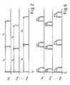
- the portable radio transmitters TX are assumed to be equal in number to n in Fig. 2 and produce the given or assigned identification number signals (ID) as successions of first through n-th bursts, respectively.
- the first portable radio transmitter TX1 produces the first bursts having a first period t1, as illustrated along a top line TX1 of Fig. 2.
- Each of the first bursts carries the first identification number signal (ID1).
- the second portable radio transmitter TX2 produces the second bursts appearing in a second period t2 which is different from the first period t1.
- each of the second bursts conveys the second identification number signal (ID2).
- the n-th bursts have an n-th period t n inherent to the n-th bursts and carry an n-th identification number signal (ID n ).
- the burst successions have different periods from one another in consideration of collision among the identification number signals (ID) in a single one of the zones Z.
- ID identification number signals
- a plurality of the burst successions illustrated in Fig. 2 collide with one another at a time instant t0.
- each radio receiver RX1, RX2, or RX3 can not receive and reproduce any identification number signals ID.
- the collision is dissolved when the next following burst is received because of the different periods of the burst successions.
- each of the first through third identification number signals (ID1) to (ID3) can be received by the first through third receivers RX1 to RX3 in the first through third zones Z1 to Z3.
- each of the first through third zones Z1 to Z3 may be called a receivable zone for the radio signals, namely, the first through third identification number signals (ID1) to (ID3).
- each of the first through third zones Z1 to Z3 may have a radius between 5 meters and 10 meters in consideration of the electric power of the first through third radio transmitters TX1 to TX3. This implies that the radio receivers may be spaced with a distance of 10-20 meters left therebetween.
- the radio receivers RX transfer the person identification numbers ID (suffix omitted) as electric identification signals to the exchange 11 through the first through third subscriber lines L10, L20, and L30 in response to the radio signals carrying the first through third identification signals.
- the illustrated exchange 11 accommodates the subscriber lines L (suffixes omitted) clustered into a plurality of groups G1, G2, and G3 which are distributed to different ones of the receivable zones Z.
- the groups G1, G2, and G3 include the subscriber lines L10, L11; L20, L21; and L30 (Fig. 1) connected to the telephone sets of the first through third zones Z1 to Z3, respectively.
- the exchange 11 also accommodates a plurality of external lines EXT, such as main wires, connected to another exchange or the like.
- the exchange 11 comprises a central control unit (CC) 21 and a switch or link unit 22 operable under control of the central control unit 21 to connect or disconnect the subscriber lines L, the external lines, and the like.
- CC central control unit
- switch or link unit 22 operable under control of the central control unit 21 to connect or disconnect the subscriber lines L, the external lines, and the like.
- the exchange 11 further comprises a subscriber memory 25 for temporarily memorizing status of each subscriber.
- the illustrated subscriber memory 25 is connected to the central control unit 21 and the switch unit 22 through buses and has a line number (LN) area 26 and an identification (ID) memory area 27.
- the line number area 26 has first local addresses which correspond to the line numbers LN, respectively, and which are loaded in a known manner with electric signals necessary for the exchange 11.
- the identification memory area 27 has second local addresses which correspond to the person identification numbers ID, respectively, and each of which is loaded with the line numbers LN assigned to the subscriber lines L.
- Each line number LN in the identification memory area 27 specifies a neighboring one of the subscriber lines, namely, telephone sets near to each person.
- the person identification numbers ID are made to correspond to the line numbers in the identification memory area 27. It is therefore possible to detect each position of the specific persons by searching the identification memory area 27 by the use of the person identification numbers ID and by reading the line numbers LN out of the identification number area 27.
- the illustrated exchange 11 further comprises an identification number receiver (ID REC) 31 for receiving the identification number signals (ID) and first and second talkie units or trunks, namely, audio response units or trunks TK1 and TK2 which are operable in a manner to be described later.
- ID REC identification number receiver
- the first zone Z1 may be called a home zone for the first person A.
- the first person A always has the first radio transmitter TX1 with him either in his pocket or otherwise.
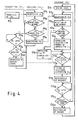
- the first identification number ID1 is generated in the manner described with reference to Fig. 2 by the first radio transmitter TX1 as the radio signal, as illustrated at a transmitter step TS1 in Fig. 4.
- the radio signal representative of the first identification number ID1 is received by the first radio receiver RX1 placed in the first zone Z1 as long as the first person A is present in his own seat, as shown at a first receiver step RS1 in Fig. 4.
- the first identification number ID1 is carried by each burst intermittently appearing at the first period t1.
- the first person A in question may happen to merely pass by and may not be staying in the first zone Z1.
- the first radio receiver RX1 monitors whether or not the first identification number ID1 is consecutively received twice or more, as shown at a second receiver step RS2 in Fig. 4.
- the second step RS2 proceeds to a third receiver step RS3. Otherwise, the second receiver step RS2 returns back to the first step RS1.
- the first radio receiver RX1 judges whether or not the first identification number ID1 was already registered in the first radio receiver RX1. If the first identification number ID1 is not registered in the first radio receiver RX1 yet, the first radio receiver RX1 registers the first identification number ID1 at a fourth receiver step RS4 through the subscriber line L10.
- the first radio receiver RX1 When the first identification number ID1 was already registered in the first radio receiver RX1, the first radio receiver RX1 must monitor whether or not the registered number, namely, the first identification number ID1 is to be erased or released from the exchange 11 because the first person A may move from the first zone Z1 to another one. For this purpose, the first radio receiver RX1 supervises lapse of a first predetermined duration T1 by the use of a timer (not shown) at a fifth receiver step RS5.
- the first predetermined duration T1 may be, for example, one minute.
- the fifth receiver step RS5 is followed by a sixth receiver step RS6 at which the receiver RX1 judges whether or not the first identification number ID1 is being received by the first radio receiver RX1. On reception of the first identification number ID1, the sixth receiver step RS6 returns back to the first receiver step RS1. Otherwise, the sixth receiver step RS6 is followed by a seventh receiver step RS7 at which the first radio receiver RX1 sends the exchange 11 an erasure signal indicative of erasure of the registered, namely, first identification number.
- the exchange 11 is put into a standby or waiting state at a first exchange step ES1 for awaiting reception of any electric identification number signals representative of the person identification numbers ID.
- the exchange 11 receives the first identification number ID1 at the identification number receiver (ID REC) 31 (Fig. 3) thereof.
- the central control unit 21 is operated at a third exchange step ES3 in a known manner to detect the line number of the subscriber line through which the first identification number ID1 is received. In the example being illustrated, the line number LN10 of the subscriber line L10 is detected by the central control unit 21.
- the central control unit 21 After detection of the line number LN10, the central control unit 21 detects whether or not the received identification number, namely, ID1 is sent from the home zone Z1, as shown at a fourth exchange step ES4. If the first identification number ID1 is sent from the home zone Z1, the central control unit 21 accesses the identification memory area 27 (Fig. 3) at a fifth exchange step ES5 to memorize the line number LN10 in a specific one of the second memory addresses that is assigned to the first identification number ID1. Thus, the line number LN10 for the first person A is memorized in the identification number memory 27 in correspondence to the first identification number ID1 for the first person A as long as he is staying in the first or home zone Z1.
- the specific address for the first identification number ID1 is loaded at a sixth exchange step ES6 with a selected one of the line numbers which are assigned to each of the remaining zones, namely, the second or the third zones Z2 or Z3.
- the selected line number may be, for example, a pilot number of each zone.
- the line numbers LN20 and LN30 are memorized in the specific address for the first identification number ID1 when the first person A is staying in the second and the third zones Z2 and Z3, respectively.
- the central control unit 21 judges whether or not the erasure signal is sent from the first radio receiver RX1 to erase contents of the specific address which are related to the first identification number ID1. Responsive to the erasure signal, the central control unit 21 erases the contents of the specific address, as shown at an eighth exchange step ES8.
- the erasure signal is produced either during a short absence of the first person A or during his long absence.
- the first person A may be in course of moving from one zone to another.
- the first person A is probably absent from the limited area.
- registration is made at a ninth exchange step ES9 in the specific address for the first identification number ID1 to indicate that the first person A is in course of movement.
- the central control unit 21 times a second predetermined duration T2 of, for example, five minutes at a tenth exchange step ES10.
- Lapse of the second predetermined duration T2 may regard the first person A as absent from the limited area.
- the central control unit 21 detects presence or absence of a request for registration related to the first identification number ID1 at an eleventh exchange step ES11 after lapse of the second predetermined duration T2. Thereafter, the central control unit 21 registers absence of the first person A in the specific address for the first identification number ID1 at a twelfth exchange step ES12.
- the line number LN10 for the telephone set T10 is memorized in the specific address assigned to the first identification number ID1 as long as the specific person A is present in the first zone Z1.
- the radio signal generated by the first radio transmitter TX1 can not be received by the first radio receiver RX1 because it is very weak in intensity as mentioned before when the first person A arrives at the seat of another person C.
- the second radio receiver TX2 in the second zone Z2 receives the radio signal of the first radio transmitter TX1.
- the first identification number ID1 is sent through the subscriber line L20 to the exchange 11.
- the identification memory area 27 is renewed from the line number LN10 into the line number LN20 at the specific address assigned to the first identification number ID1.
- the identification memory area 27 is successively and automatically renewed at the specific address assigned to the first identification number ID1 as the first person A moves in the limited area. Similar operation is carried out as regards the second and the third persons D and E.
- the identification memory area 27 is renewed only when each specific person changes the zones from one to another. Accordingly, it is possible to prevent the subscriber lines, such as L10, L20, and L30, from being occupied by the radio receivers for a long time. Consequently, usual communication is also carried out through the subscriber lines L10, L20, and L30.
- Fig. 5 afresh and Figs. 1 and 3 again, operation of the central control unit 21 will be described on the assumption that the exchange 11 receives a terminating call through one of the subscriber lines L and the external lines EXT, as shown at a first processing step PS1 in Fig. 5.
- the terminating call is accompanied either by a directory number TEL or by a person identification number ID. If the directory number TEL is detected at a second processing step PS2, the central control unit 21 rings one of the telephone sets that is indicated by the directory number TEL, as shown at a third processing step PS3.
- the central control unit 21 accesses the identification memory area 27 at a fourth processing step PS4 to detect contents of an address assigned to the person identification number ID at a fifth processing step PS5.
- the central control unit 21 energizes the first talkie unit TK1 (Fig. 3) at a sixth processing step PS6.
- the first talkie unit TK1 gives information upon a short absence in the form of an audio signal.
- the fifth processing step PS5 is followed by a seventh processing step PS7 at which the central processing unit 21 judges whether or not he is absent from the limited area.
- the seventh processing step PS7 is succeeded by a ninth processing step PS9 at which the line number LN is detected from the contents of the address for the person identification number ID.
- the central control unit 21 judges at a tenth processing step PS10 whether or not the subscriber line L specified by the line number LN is put into a busy state. Unless the subscriber line LN is busy, the central control unit 21 rings one of the telephone sets that is placed in a destination one of the zones Z and is connected to the subscriber line LN in the destination zone, as shown at an eleventh processing step PS11.
- the telephone sets in the destination zone are successively searched to detect an idle one of the telephone sets in the order of priority predetermined in the destination zone when one of the telephone sets in the destination zone is put into a busy state.
- the central control unit 21 matches states of the subscriber lines L included in the destination zone in the order of the priority. For example, judgement is made at a twelfth processing step PS12 to indicate whether or not the subscriber line of second priority is busy. Similarly, judgement is made as regards the subscriber line of third priority at a thirteenth processing step PS13.
- one of the telephone sets is rung in the destination zone at the eleventh processing step PS11, if an idle one of the subscriber lines L is found out.
- a destination of each specific person is automatically sought by the central control unit 21 with reference to each person identification number ID to ring a neighboring one of the telephone sets through the switch unit 22.
- a busy tone is produced as shown at a fifteenth processing step PS15.
- a combination of the central control unit 21 and the switch unit 22 serves to transfer the terminating call and may be called a call transfer member.
- the above-mentioned call transfer is carried out only when one of the person identification numbers ID is given to the exchange 11. If a particular one of persons is informed of the one of the person identification numbers assigned to a specific person and calls the specific person by the use of the one person identification number only in case of emergency, an emergent call alone is favorably transferred to the specific person. In addition, the call transfer is carried out without any manual operation.
- an automatic call transfer system carries out automatic call transfer by the use of first through n-th burst successions as illustrated along top through bottom lines TX1 to TX n of Fig. 6. More particularly, each burst succession has a pair of bursts each of which carries a person identification number assigned to each specific person. The bursts of each pair consist of a leading and a trailing one.
- the illustrated leading bursts of each burst succession are repeated at a period peculiar to the burst succession, like the burst successions illustrated in Fig. 2. Therefore, the first burst succession illustrated along the top line TX1 of Fig. 6 includes the leading bursts appearing in the first period t1 as shown in Fig. 2. Likewise, the second through n-th burst successions TX2 to TX n include the leading bursts having the second through n-th periods t2 to t n , respectively.
- each burst succession has the period, such as t1, t2, ..., or t n , and the time interval, such as ⁇ t1, ⁇ t2, ..., or ⁇ t n , peculiar thereto.
- the radio receiver RX can not distinguish the person identification numbers ID from one another. However, the radio receiver can receive each person identification number twice after both of each time interval ⁇ t (suffixes omitted) and each period t. The person identification numbers are therefore rapidly detected twice or more from each burst succession in comparison with the burst successions illustrated in Fig. 2.
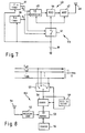
- each radio transmitter TX comprises first and second timers 36 and 37 for measuring each period t and each time interval ⁇ t both of which are peculiar to the burst succession, respectively.
- the first and second timers 36 and 37 are always energized by a battery 39 to produce a succession of first pulses P1 at each period t and a succession of second pulses P2 appearing when each time interval ⁇ t lapses after the first pulses P1.
- the first and the second pulses P1 and P2 last during the bursts.
- a switch 41 is closed during presence of the first and the second pulses P1 and P2 to intermittently connect the battery 39 to an identification signal circuit 43.
- the identification signal circuit 43 comprises an identification (ID) number generator 45, a modulator 46, and an amplifier 47, which are all simultaneously energized by the battery 39.
- the person identification number is intermittently generated by the identification number generator 45 and is subjected to modulation and amplification by the modulator 46 and the amplifier 47 to be produced as a radio signal through an antenna 48.
- the radio signal is received by a radio receiver RX illustrated in Fig. 8 and is sent through a reception antenna 51 to a decoding circuit 52 to be decoded into a decoded signal representative of the person identification number ID.
- the decoded signal is memorized in an identification number memory 53 and is counted by a counter 54 which is counted up at every reception of the decoded signal.
- the identification number memory 53 sends the decoded signal through a sender 56 and a selector 57 to one of the subscriber lines indicated at L a1 , L a2 , ..., and L am .
- a busy detector 59 is coupled to the sender 56 and the selector 57.
- the busy detector 59 successively searches the subscriber lines L a1 to L am to detect an idle one of the subscriber lines L a1 to L am .
- the busy detector 59 connects the selector 57 to the idle subscriber line.
- the decoded signal carrying the person identification number is sent through the idle subscriber line to the exchange 11.
- the illustrated radio receiver RX is assigned with a plurality of the subscriber lines L a1 to L am .
- the terminating call is automatically transferred to each of the specific persons given the person identification numbers even when each specific person frequently changes a destination from one to another in the limited area and even when each specific person forgets to inform of change of the destination.
- the above-mentioned call transfer can be individually carried out about each of persons to which a single telephone is dispensed, when the different person identification numbers are assigned to the respective persons.
- the periods t1 through t n of the bursts may be decided in consideration of the number of the specific persons, areas of the zones, and electric power of the radio transmitters. Preferably, the periods t are longer than a time necessary for passing through each zone. Therefore, production of the bursts results in a reduction of electric power consumption in each radio transmitter TX.
- each of the radio receivers may convert the person identification number ID into an electric signal of a frequency band higher than an audio frequency band.
- the electric signal may thereafter be subjected to demodulation by the exchange 11 to be rendered into the audio frequency band.
- an offering connection may be made to preferentially carry out call transfer on reception of a terminating call when a subscriber line in question is busy.
- each radio receiver may directly transfer the received person identification numbers ID to the exchange 11 without passing through the identification memory 53 as illustrated in Fig. 8.
- the central control unit 21 should carry out operations as illustrated at the second through seventh receiver steps RS2 to RS7 (Fig. 4) instead of the radio receivers RX, although the subscriber lines L10, L20, and L30 may be occupied by the radio receivers RX for a long time.
- the radio receivers RX may not always be connected in parallel to the telephone sets, such as T10, T20, and T30, but may be connected through exclusive lines.
- the bursts illustrated in Figs. 2 and 6 may be variable in their periods and time intervals to avoid concurrent occurrence of the bursts.
- the person identification numbers ID may be produced in a frequency division fashion when the exchange 11 has a comparatively small capacity and may be continuously produced by each radio transmitter.
- the exchange may not be a private branch exchange.
- each person identification number may be received by a plurality of the radio receivers RX. If an intersected portion includes the home zone, the person identification number may be registered in the home zone in preference to the other zone or zones.
- the person identification number may be registered in one of the receivable zones that receives a new one of the person identification numbers.
- the receivable zones may not always cover the whole of the limited area because the short absence can be indicated in the illustrated system.
- ultrasonic waves may be used to couple the transmitters TX to the receivers RX instead of the radio signals.
- An inductive radio method may be used to couple the transmitters TX and the receivers RX.
Landscapes
- Engineering & Computer Science (AREA)
- Signal Processing (AREA)
- Mobile Radio Communication Systems (AREA)
Claims (7)
- Automatisches Anrufweiterleitungssystem zur Verwendung beim automatischen Durchführen einer Anrufweiterleitung mittels einer Vermittlung, die über Teilnehmerleitungen jeweils mit Telefonapparaten verbunden ist, wobei die Telefonnummern mit den Leitungsnummern, die jeweils den Teilnehmerleitungen entsprechen, bestimmt werden und in einem Bereich verteilt sind, so daß diese von Personen, die sich in diesem Bereich bewegen, genutzt werden können, wobei
eine Personenidentifikationsnummer jeder der bestimmten Personen zugeordnet wird, so daß diese bestimmte Person identifizierbar ist,
das System aufweist:
mehrere Empfangseinrichtungen (RX), die mit der Vermittlung verbunden sind und zu Empfangszonen, in die der Bereich unterteilt ist, zugeordnet sind, Telefonapparate in diesen Empfangszonen vorhanden sind, jede der Empfangseinrichtungen zum Empfangen eines Identifikationsnummersignals dient, daß die Personenidentifikationssnummer darstellt und
Signalerzeugungseinrichtungen (TX), die von jeder bestimmten Person mitgeführt werden, zum Erzeugen des Identifikationsnummersignals, das von einer der ausgewählten Empfangseinrichtungen empfangen wird, wenn sich jede bestimmte Person in der Empfangszone dieser ausgewählten Empfangseinrichtung aufhält,
die Vermittlung aufweist:
eine Speichereinrichtung (25), die mit den Empfangseinrichtungen verbunden ist, zum Speichern einer bestimmten Leitungsnummer der Empfangszone für die ausgewählte Empfangseinrichtung entsprechend dem Identifikationsnummersignal, und
eine Anrufweiterleitungseinrichtung (21), die mit der Speichereinrichtung verbunden ist und auf den Anruf anspricht, mit der die Personenidentifikationsnummer trägt, zum Weiterleiten des Anrufs an den Telefonapparat, der durch die bestimmten Leitungsnummern mit Bezug auf das gespeicherte Identifikationsnummernsignal bezeichnet und die sich in der Empfangszone für die ausgewählte Empfangseinrichtung aufhält,
dadurch gekennzeichnet,
a) daß mindestens zwei Telefonapparate in jeder Empfangszone vorhanden sind,b) daß die Speichereinrichtung (25) mindestens zwei bestimmte Leitungsnummern speichert undc) daß die Anrufweiterleitungseinrichtung (21) zum Weiterleiten des Anrufers diesen Anruf an einen anderen der Telefonapparate weiterleitet, der in der Empfangszone für die ausgewählte Empfangseinrichtung angeordnet ist, wenn die eine bestimmte Leitungsnummer in einem Besetzzustand (PS10 bis PS13) gehalten wird. - Automatisches Anrufweiterleitungssystem nach Anspruch 1, wobei die Signalerzeugungseinrichtung (TX) das Identifikationsnummersignal in der Form eines Funksignals erzeugt während jede der Empfangseinrichtungen (RX) ein elektrisches Identifikationssignal, das die Personenidentifikationsnummer darstellt, in Abhängigkeit von dem Funksignal erzeugt.
- Automatisches Anrufweiterleitungssystem nach Anspruch 2, wobei die Signalerzeugungseinrichtung (TX) aufweist:
eine Impulsfolgeerzeugungseinrichtung (45) zum Erzeugen einer Folge von Impulsfolgen, die jeweils das Identifikationsnummersignal tragen und eine bestimmte für die Personenidentifikationsnummer einzigartige Zeitdauer haben und
Einrichtungen (46, 47, 48) zum Erzeugen dieser Folge als das Funksignal. - Automatisches Anrufweiterleitungssystem nach Anspruch 2, wobei die Signalerzeugungseinichtung (TX) aufweist:
eine Impulsfolge-Paar-Erzeugungseinrichtung (45) zum wiederholten Erzeugen eines Pulsfolgepaars, das jeweils die Personenidentifikationnummer trägt, wobei die Impulsfolgen jedes Paars mit einem zwischen ihnen liegenden Impulsfolgeintervall auftreten, der für die Personenidentifikationsnummer bestimmt ist und
Einrichtungen (46, 47, 48) zum Erzeugen dieses Impulsfolgepaars als das Funksignal. - Automatisches Anrufweiterleitungssystem nach einem der Ansprüche 2 bis 4, wobei jede der Empfangseinrichtungen (RX) aufweist:
eine lokale Speichereinrichtung (53) zum Speichern des elektrischen Identifikationssignals, und
eine Sendeeinrichtung (56), die das gespeicherte elektrische Identifikationssignal nur beim Auftreten einer Veränderung der Personenidentifikationsnummer, die von dem Funksignal getragen wird, an die Vermittlung sendet. - Automatisches Anrufweiterleitungssystem nach Anspruch 5, wobei jede der Empfangseinrichtungen ferner aufweist:
eine Überwachungseinrichtung (59), die mit der Sendeeinrichtung und den Teilnehmerleitungen für jede Empfangszone verbunden ist, zum Überwachen der Teilnehmerleitungen, so daß eine freie Teilnehmerleitung erkannt wird und das gespeicherte elektrische Identifikationssignal an die freie Teilnehmerleitung geliefert wird. - Automatisches Anrufweiterleitungssystem nach einem der Ansprüche 1 bis 6, wobei die Signalerzeugungseinrichtung (TX) mit jedem der Empfänger (RX) mittels Ultraschallwellen verbunden ist.
Applications Claiming Priority (2)
| Application Number | Priority Date | Filing Date | Title |
|---|---|---|---|
| JP25506/84 | 1984-02-14 | ||
| JP59025506A JPS60170341A (ja) | 1984-02-14 | 1984-02-14 | 交換方式 |
Publications (3)
| Publication Number | Publication Date |
|---|---|
| EP0152908A2 EP0152908A2 (de) | 1985-08-28 |
| EP0152908A3 EP0152908A3 (en) | 1988-01-27 |
| EP0152908B1 true EP0152908B1 (de) | 1991-12-27 |
Family
ID=12167948
Family Applications (1)
| Application Number | Title | Priority Date | Filing Date |
|---|---|---|---|
| EP85101557A Expired EP0152908B1 (de) | 1984-02-14 | 1985-02-13 | Automatisches Anrufumleitungssystem fähig zur Erledigung der Anrufumleitung ohne manuelle Bedienung |
Country Status (8)
| Country | Link |
|---|---|
| US (1) | US4658416A (de) |
| EP (1) | EP0152908B1 (de) |
| JP (1) | JPS60170341A (de) |
| AU (1) | AU566854B2 (de) |
| CA (1) | CA1235218A (de) |
| DE (1) | DE3584983D1 (de) |
| HK (1) | HK30293A (de) |
| SG (1) | SG128192G (de) |
Cited By (9)
| Publication number | Priority date | Publication date | Assignee | Title |
|---|---|---|---|---|
| US5751760A (en) | 1984-09-14 | 1998-05-12 | Aspect Telecommunications Corporation | Controller for a telephone system with code screening of incoming calls |
| US5924016A (en) | 1984-09-14 | 1999-07-13 | Aspect Telecommunications Corporation | Control and monitoring apparatus and method for a telephone system |
| US6026156A (en) | 1994-03-18 | 2000-02-15 | Aspect Telecommunications Corporation | Enhanced call waiting |
| US6201950B1 (en) | 1984-09-14 | 2001-03-13 | Aspect Telecommunications Corporation | Computer-controlled paging and telephone communication system and method |
| US6411682B1 (en) | 1995-09-21 | 2002-06-25 | Aspect Telecommunications Corporation | Computer controlled paging and telephone communication system and method |
| US6453164B1 (en) | 1989-11-21 | 2002-09-17 | Aspect Communications Corporation | Intelligent telephone control system which allows subscribers to remotely control a plurality of call handling utilities |
| US6545589B1 (en) | 1984-09-14 | 2003-04-08 | Aspect Communications Corporation | Method and apparatus for managing telecommunications |
| US6748054B1 (en) | 1997-09-08 | 2004-06-08 | Worldcom, Inc. | Single telephone number access to multiple communications services |
| US7088801B1 (en) | 1997-09-08 | 2006-08-08 | Mci, Inc. | Single telephone number access to multiple communications services |
Families Citing this family (124)
| Publication number | Priority date | Publication date | Assignee | Title |
|---|---|---|---|---|
| US5825867A (en) * | 1984-09-14 | 1998-10-20 | Aspect Telecommunications Corporation | Enhanced call waiting |
| JPS61228533A (ja) * | 1985-04-03 | 1986-10-11 | Hitachi Ltd | 電子計算機におけるセツシヨンの制御方法 |
| SE448199B (sv) * | 1985-05-09 | 1987-01-26 | Ericsson Telefon Ab L M | Anleggning med flera berbara, snorlosa telefonapparater |
| JPS61274531A (ja) * | 1985-05-30 | 1986-12-04 | Nec Corp | チヤネル選択方式 |
| US4876740A (en) * | 1985-08-30 | 1989-10-24 | Motorola, Inc. | Radiotelephone system employing digitized speech/data signalling |
| US6433668B1 (en) * | 1990-05-25 | 2002-08-13 | Seiko Instruments Inc. | Paging system with spacial, frequency and time diversity |
| AT384707B (de) * | 1985-12-09 | 1987-12-28 | Funktaxi 3130 Vermittlungsgese | Einrichtung zur vermittlung von lohnfuhrwerken |
| US4752951A (en) * | 1985-12-23 | 1988-06-21 | Konneker Lloyd K | Method of providing location dependent person locator service |
| DE3786590T2 (de) * | 1986-04-26 | 1994-02-24 | Nippon Electric Co | Funktelefonsystem mit gemeinsamem Signalisierungskanal. |
| JP2503418B2 (ja) * | 1986-05-23 | 1996-06-05 | 日本電気株式会社 | 自動電話交換機の中継台扱者検出装置 |
| JPS6392132A (ja) * | 1986-10-06 | 1988-04-22 | Toshiba Corp | コ−ドレス電話装置 |
| US5210786A (en) * | 1986-10-15 | 1993-05-11 | Iwatsu Electric Co. Ltd. | Portable telephone system using stratified exchange system |
| USRE33417E (en) * | 1986-10-27 | 1990-10-30 | Mobile Telecommunication Technologies Corporation | Mobile paging call back system and related method |
| US4775999A (en) * | 1986-10-31 | 1988-10-04 | Motorola, Inc. | Registration of radiotelephones in networked cellular radiotelephone systems |
| JPS63152255A (ja) * | 1986-12-17 | 1988-06-24 | Stanley Electric Co Ltd | 電話交換システム |
| GB2198910B (en) * | 1986-12-17 | 1990-09-05 | Stanley Electric Co Ltd | Telephone exchange system |
| JPS63152257A (ja) * | 1986-12-17 | 1988-06-24 | Stanley Electric Co Ltd | 電話交換システム |
| JP2566948B2 (ja) * | 1987-04-03 | 1996-12-25 | 日本電気株式会社 | 広域コ−ドレス電話方式 |
| JP2693761B2 (ja) * | 1987-04-03 | 1997-12-24 | 日本電気株式会社 | 移動通信方式 |
| JP2514085B2 (ja) * | 1987-04-10 | 1996-07-10 | モトローラ・インコーポレーテツド | ネットワ―ク化セル状無線電話システムにおける移動無線電話機の登録方法及び該移動無線電話機をペ―ジングする方法 |
| JP2516983B2 (ja) * | 1987-06-19 | 1996-07-24 | 松下通信工業株式会社 | 無線電話装置 |
| JPS6451751A (en) * | 1987-08-21 | 1989-02-28 | Matsushita Electric Industrial Co Ltd | Telephone system |
| JPS6454889A (en) * | 1987-08-25 | 1989-03-02 | Nec Corp | Private branch electronic exchange with subscriber's number numbering function |
| US5280521A (en) * | 1987-10-09 | 1994-01-18 | Iwatsu Electric Co., Ltd. | Portable telephone system |
| JP2698587B2 (ja) * | 1987-11-10 | 1998-01-19 | 株式会社東芝 | 通信システム |
| JP2548763B2 (ja) * | 1988-01-25 | 1996-10-30 | 富士通株式会社 | 移動体通信の通話中ゾーン切換え方法と制御交換局 |
| US4833701A (en) * | 1988-01-27 | 1989-05-23 | Motorola, Inc. | Trunked communication system with nationwide roaming capability |
| JP2624760B2 (ja) * | 1988-04-01 | 1997-06-25 | 株式会社日立製作所 | 移動無線電話システム |
| JPH0215761A (ja) * | 1988-07-01 | 1990-01-19 | Sanyo Electric Co Ltd | 着信加入者追跡方式及び同方式用送信機並びに同方式用内線電話機 |
| US4914649A (en) * | 1988-09-12 | 1990-04-03 | Motorola, Inc. | Multiple frequency message system |
| US4901340A (en) * | 1988-09-19 | 1990-02-13 | Gte Mobilnet Incorporated | System for the extended provision of cellular mobile radiotelephone service |
| US5063588A (en) * | 1988-11-21 | 1991-11-05 | Motorola, Inc. | Communication system providing automatic identification of calling parties |
| US5860136A (en) * | 1989-06-16 | 1999-01-12 | Fenner; Peter R. | Method and apparatus for use of associated memory with large key spaces |
| US5134645A (en) * | 1989-06-30 | 1992-07-28 | Berken James J | Automatic and sustained association of users with communications paths |
| US5144648A (en) * | 1989-08-30 | 1992-09-01 | Mobile Telecommunication Technologies | Method and apparatus for processing pages |
| US5090050A (en) * | 1989-09-14 | 1992-02-18 | Contel Cellular Inc. | Method and apparatus for communicating with radio telephones |
| US5070521A (en) * | 1989-09-25 | 1991-12-03 | Motorola, Inc. | Method and apparatus for call source identification |
| JPH03139947A (ja) * | 1989-10-25 | 1991-06-14 | Pfu Ltd | 選択接続電話システム |
| US5127045A (en) * | 1989-11-16 | 1992-06-30 | Cragun David R | Identifying telephone controller system |
| US4980907A (en) * | 1989-12-15 | 1990-12-25 | Telefonaktiebolaget L M Ericsson | Telecommunication combination comprising a telepoint and a portable radio terminal |
| ATE128311T1 (de) * | 1990-03-08 | 1995-10-15 | Ericsson Telefon Ab L M | System und verfahren zur dynamischen zuteilung von streifen leitweglenkungsnummern. |
| JPH03270453A (ja) * | 1990-03-20 | 1991-12-02 | Fujitsu Ltd | 自動追い掛け電話装置 |
| US5206855A (en) * | 1990-04-06 | 1993-04-27 | Motorola, Inc. | Multiple frequency message system |
| US5018187A (en) * | 1990-06-05 | 1991-05-21 | At&T Bell Laboratories | Mobile telephone intrasystem and intersystem enhanced handoff method and apparatus for limiting trunk switching connections |
| JPH0454027A (ja) * | 1990-06-21 | 1992-02-21 | Victor Co Of Japan Ltd | 通信システム |
| US5197092A (en) * | 1990-10-31 | 1993-03-23 | Mccaw Cellular Communications, Inc. | Location registration system for a personal communicator such as a cellular telephone |
| US5243645A (en) * | 1990-11-01 | 1993-09-07 | At&T Bell Laboratories | Automatic system for forwarding of calls |
| KR920015943A (ko) * | 1991-01-22 | 1992-08-27 | 정용문 | 페이저를 이용한 사설교환기의 호 연결방법 |
| US5610973A (en) * | 1991-01-28 | 1997-03-11 | Bellsouth Corporation | Interactive roamer contact system for cellular mobile radiotelephone network |
| GB9107650D0 (en) * | 1991-04-11 | 1991-05-29 | Gen Electric Co Ltd | Active device for pabx control |
| US5325424A (en) * | 1991-04-22 | 1994-06-28 | Motorola, Inc. | Method of automatically establishing a communication path between two devices |
| US5311570A (en) * | 1991-05-10 | 1994-05-10 | At&T Bell Laboratories | Integration of wireless paging in a communication system |
| US5315636A (en) * | 1991-06-28 | 1994-05-24 | Network Access Corporation | Personal telecommunications system |
| CA2076434C (en) * | 1991-10-09 | 1996-07-02 | Gary Joe Grimes | Incoming communications forwarding technique utilizing a called party location indicator |
| WO1993009629A1 (en) * | 1991-11-04 | 1993-05-13 | Motorola, Inc. | Method and apparatus for reserving a communication path in a telepoint communications system |
| JPH05130227A (ja) * | 1991-11-07 | 1993-05-25 | Fujitsu Ltd | 無線カードによる移動先自動管理装置 |
| US5335278A (en) * | 1991-12-31 | 1994-08-02 | Wireless Security, Inc. | Fraud prevention system and process for cellular mobile telephone networks |
| US5353331A (en) * | 1992-03-05 | 1994-10-04 | Bell Atlantic Network Services, Inc. | Personal communications service using wireline/wireless integration |
| US5579379A (en) * | 1992-03-05 | 1996-11-26 | Bell Atlantic Network Services, Inc. | Personal communications service having a calling party pays capability |
| US5408419A (en) * | 1992-04-14 | 1995-04-18 | Telefonaktiebolaget L M Ericsson | Cellular radiotelephone system signalling protocol |
| JPH05344224A (ja) * | 1992-06-10 | 1993-12-24 | Nec Commun Syst Ltd | 構内電話交換システムの着信転送電話番号自動登録方式 |
| US5363425A (en) * | 1992-06-29 | 1994-11-08 | Northern Telecom Limited | Method and apparatus for providing a personal locator, access control and asset tracking service using an in-building telephone network |
| US5341410A (en) * | 1992-07-21 | 1994-08-23 | Ram Mobile Data Usa Limited Partnership | Cellular telephone locator using a mobile data system |
| JPH06188995A (ja) * | 1992-08-31 | 1994-07-08 | American Teleph & Telegr Co <Att> | 呼経路指定伝送装置およびその方法 |
| ATA65993A (de) * | 1993-04-01 | 1996-04-15 | Schnallinger Helfried Ing | Telefonanlage |
| US5548637A (en) * | 1993-09-09 | 1996-08-20 | Precision Tracking Fm, Inc. | Method and apparatus for locating personnel and objects in response to telephone inquiries |
| CA2117934A1 (en) * | 1993-12-02 | 1995-06-03 | Steven C. Salimando | Automatic location identification and call forwarding techniques |
| DE4344702A1 (de) * | 1993-12-27 | 1995-07-06 | Deutsche Bundespost Telekom | Verfahren und Anordnung zum wechselweisen Betreiben eines mobilen Endgerätes über ein zellulares Mobilfunksystem und ein Schnurlossystem in einem Festnetz |
| CA2137383C (en) * | 1994-01-03 | 2001-02-13 | Gary Len Griffith | A switching arrangement for handling wireless terminals with switch features for handling wired terminals |
| US5400338A (en) * | 1994-02-08 | 1995-03-21 | Metricom, Inc. | Parasitic adoption of coordinate-based addressing by roaming node |
| US5862208A (en) * | 1994-02-16 | 1999-01-19 | Priority Call Management, Inc. | Method and system for enabling a party to change terminals during a call |
| AU683561B2 (en) * | 1994-06-27 | 1997-11-13 | Nec Corporation | Cellular telephone with wire connection function |
| US5673308A (en) * | 1994-10-12 | 1997-09-30 | Bell Atlantic Network Services, Inc. | Personal phone number system |
| US5745850A (en) * | 1994-10-24 | 1998-04-28 | Lucent Technologies, Inc. | Apparatus and method for mobile (e.g. cellular or wireless) telephone call handover and impersonation |
| US5553128A (en) * | 1994-10-26 | 1996-09-03 | Lucent Technologies Inc. | Control of call forwarding by a target telephone |
| US5649286A (en) * | 1994-11-14 | 1997-07-15 | Bellsouth Corporation | Method for managing the registration of a wireless unit |
| JPH08149559A (ja) * | 1994-11-18 | 1996-06-07 | Canon Inc | 無線通信装置 |
| US5825864A (en) * | 1994-12-08 | 1998-10-20 | Scientific And Commercial Systems Corporation | Personal automatic registration system with call forwarding |
| US5649003A (en) * | 1995-02-27 | 1997-07-15 | At&T | Method in a communications systems for providing an out-of-band signaling response based on predetermined conditions |
| CA2172564C (en) | 1995-04-28 | 1999-12-28 | Mark Jeffrey Foladare | Call redirection system |
| US5724417A (en) * | 1995-09-11 | 1998-03-03 | Lucent Technologies Inc. | Call forwarding techniques using smart cards |
| US5621787A (en) * | 1995-09-13 | 1997-04-15 | Bell Atlantic Network Services, Inc. | Prepaid cash card |
| CA2190672C (en) * | 1995-12-27 | 2000-05-23 | Mark Jeffrey Foladare | Communication system and method using two-way paging to provide call control |
| CA2190671C (en) * | 1995-12-27 | 2000-10-24 | Mark Jeffrey Foladare | Communication system and method using two-way paging to provide call control |
| GB9606739D0 (en) * | 1996-03-29 | 1996-06-05 | British Telecomm | Telecommunications apparatus and method |
| US5918181A (en) * | 1996-10-15 | 1999-06-29 | Tatung Telecom Corporation | Method and apparatus for tracking location of wireless terminals in a nanocellular digital cordless terminal network coupled to a local exchange |
| US6563914B2 (en) | 1997-02-26 | 2003-05-13 | Call Sciences Limited | Personal web-based teleconferencing method and system |
| US6587867B1 (en) | 1997-05-22 | 2003-07-01 | Mci Communications Corporation | Internet-based subscriber profile management of a communications system |
| US6125176A (en) * | 1997-06-17 | 2000-09-26 | At&T Corporation | Method and system for routing calls based on conditions of electronic devices |
| US6018575A (en) | 1997-09-08 | 2000-01-25 | Mci Worldcom | Direct distance dialing (DDD) access to a communications services platform |
| US6931116B1 (en) | 1997-09-08 | 2005-08-16 | Mci Communications Corporation | Multiple routing options in a telecommunications service platform |
| US6330079B1 (en) | 1997-09-08 | 2001-12-11 | Mci Communications Corporation | Integrated voicemail and faxmail platform for a communications system |
| US7194078B2 (en) * | 1998-05-28 | 2007-03-20 | Siemens Communications, Inc. | Network redirection control routing |
| US6473437B2 (en) | 1998-07-02 | 2002-10-29 | Siemens Information And Communication Networks, Inc. | Network call park service |
| FI106234B (fi) * | 1998-11-27 | 2000-12-15 | Helsingin Puhelin Oyj | Menetelmä tavoitettavuuspalvelun ohjaamiseksi |
| GB0006614D0 (en) * | 2000-03-02 | 2000-05-10 | Pressurecall Ltd | Improved communication system |
| EP1284082A2 (de) * | 2000-05-26 | 2003-02-19 | Telefonaktiebolaget LM Ericsson (publ) | Verfahren zur erinnerung an eine aktivierte anrufweiterleitung |
| US7382911B1 (en) | 2001-02-16 | 2008-06-03 | Hand Held Products, Inc. | Identification card reader |
| US7120238B1 (en) * | 2001-07-12 | 2006-10-10 | 8X8, Inc. | Sensor-controlled telephone system |
| US7472825B2 (en) * | 2002-01-11 | 2009-01-06 | Hand Held Products, Inc. | Transaction terminal |
| US7121470B2 (en) * | 2002-01-11 | 2006-10-17 | Hand Held Products, Inc. | Transaction terminal having elongated finger recess |
| US7479946B2 (en) * | 2002-01-11 | 2009-01-20 | Hand Held Products, Inc. | Ergonomically designed multifunctional transaction terminal |
| US7748620B2 (en) * | 2002-01-11 | 2010-07-06 | Hand Held Products, Inc. | Transaction terminal including imaging module |
| US7451917B2 (en) * | 2002-01-11 | 2008-11-18 | Hand Held Products, Inc. | Transaction terminal comprising imaging module |
| EP1370102A1 (de) * | 2002-10-22 | 2003-12-10 | Siemens Aktiengesellschaft | Verfahren und System zum Leiten von Kommunikation |
| US7082192B2 (en) * | 2002-11-07 | 2006-07-25 | International Business Machines Corporation | Locale based call forwarding |
| US20040107128A1 (en) * | 2002-11-07 | 2004-06-03 | International Business Machines Corporation | Behavior based life support services |
| US6999573B2 (en) * | 2002-11-07 | 2006-02-14 | International Business Machines Corporation | Locale based call forwarding with automated creation of new locales |
| US20040116782A1 (en) * | 2002-12-17 | 2004-06-17 | International Business Machines Corporation | Behavior based life support with abstract behavior patterns |
| US20040116781A1 (en) * | 2002-12-17 | 2004-06-17 | International Business Machines Corporation | Behavior based life support generating new behavior patterns from historical behavior indicators |
| US20040143453A1 (en) * | 2002-12-17 | 2004-07-22 | International Business Machines Corporation | Behavior based life support with default behavior patterns |
| US20040116783A1 (en) * | 2002-12-17 | 2004-06-17 | International Business Machines Corporation | Behavior based life support generating new behavior patterns from behavior indicators for a user |
| GB0411150D0 (en) * | 2004-05-19 | 2004-06-23 | Queen Mary & Westfield College | Vaccine |
| PL1601213T3 (pl) * | 2004-05-19 | 2006-09-29 | Swisscom Ag | Sposób i system automatycznej zmiany kierunku wywołania |
| DE502004006628D1 (de) * | 2004-09-29 | 2008-04-30 | Swisscom Mobile Ag | Verfahren und system zur eingabe von benutzerbefehlen einer benutzersteuerbaren telekommunikationsvorrichtung |
| US7172114B2 (en) * | 2004-12-30 | 2007-02-06 | Hand Held Products, Inc. | Tamperproof point of sale transaction terminal |
| US8723804B2 (en) * | 2005-02-11 | 2014-05-13 | Hand Held Products, Inc. | Transaction terminal and adaptor therefor |
| US20060277093A1 (en) * | 2005-05-26 | 2006-12-07 | Barnhouse William Iii | System and method of automatic polling |
| US20080153472A1 (en) * | 2006-12-21 | 2008-06-26 | International Business Machines Corporation | Systems and methods for a cellular phone gateway |
| US8265248B2 (en) | 2008-02-07 | 2012-09-11 | Microsoft Corporation | Techniques for transfer error recovery |
| WO2010021567A1 (ru) * | 2008-08-15 | 2010-02-25 | Zhukov Vladimir Gennadyevich | Система переадресации вызовов с одновременным контролем перемещения лиц, находящихся на территории предприятия или в производственном, либо служебном помещении |
| JP6525276B2 (ja) * | 2016-07-25 | 2019-06-05 | Necプラットフォームズ株式会社 | 呼制御装置及び通信端末 |
| US11715056B2 (en) | 2021-03-16 | 2023-08-01 | Bank Of America Corporation | Performance monitoring for communication systems |
| US11595527B2 (en) | 2021-03-16 | 2023-02-28 | Bank Of America Corporation | Dynamic routing for communication systems |
Family Cites Families (15)
| Publication number | Priority date | Publication date | Assignee | Title |
|---|---|---|---|---|
| FR1599160A (de) * | 1968-02-01 | 1970-07-15 | ||
| US4057790A (en) * | 1974-05-24 | 1977-11-08 | George William Fleming | Personal aid signalling system |
| US4178475A (en) * | 1978-03-09 | 1979-12-11 | General Communications Co., Inc. | Method and control apparatus for radio paging systems |
| US4174476A (en) * | 1978-05-11 | 1979-11-13 | Owens-Illinois, Inc. | Laser cutting of tubular articles |
| US4336524A (en) * | 1979-07-17 | 1982-06-22 | Levine Alfred B | Video display pager receiver with memory |
| DE2929961A1 (de) * | 1979-07-24 | 1981-02-12 | Itt Ind Gmbh Deutsche | Fernsprechanlage mit personensuchsystem |
| US4479124A (en) * | 1979-09-20 | 1984-10-23 | Texas Instruments Incorporated | Synthesized voice radio paging system |
| US4313035A (en) * | 1980-01-18 | 1982-01-26 | Bell Telephone Laboratories, Incorporated | Method of providing person locator service |
| JPS57210738A (en) * | 1981-06-19 | 1982-12-24 | Nec Corp | Callout connecting system for missing person |
| DE3137024A1 (de) * | 1981-09-17 | 1983-03-24 | Siemens AG, 1000 Berlin und 8000 München | Kennungsmeldesystem zur vollautomatischen teilnehmerstandorterfassung in einem mobilkommunikationsnetz, insbesondere in einem drahtgebundenen mobilkommunikationsnetz |
| US4468813A (en) * | 1982-12-06 | 1984-08-28 | Motorola, Inc. | Digital voice storage system |
| US4577060A (en) * | 1983-05-18 | 1986-03-18 | Bbl Industries, Inc. | Paging network |
| US4567323A (en) * | 1983-07-12 | 1986-01-28 | At&T Bell Laboratories | Method and apparatus for providing a plurality of special services |
| US4577066A (en) * | 1983-08-03 | 1986-03-18 | At&T Bell Laboratories | Telephone interexchange call routing |
| US4577062A (en) * | 1983-09-02 | 1986-03-18 | Butler National Corporation | Method for dispensing information |
-
1984
- 1984-02-14 JP JP59025506A patent/JPS60170341A/ja active Pending
-
1985
- 1985-02-11 US US06/700,107 patent/US4658416A/en not_active Expired - Lifetime
- 1985-02-13 CA CA000474210A patent/CA1235218A/en not_active Expired
- 1985-02-13 EP EP85101557A patent/EP0152908B1/de not_active Expired
- 1985-02-13 DE DE8585101557T patent/DE3584983D1/de not_active Expired - Lifetime
- 1985-02-14 AU AU38705/85A patent/AU566854B2/en not_active Ceased
-
1992
- 1992-12-17 SG SG1281/92A patent/SG128192G/en unknown
-
1993
- 1993-03-25 HK HK302/93A patent/HK30293A/en not_active IP Right Cessation
Cited By (20)
| Publication number | Priority date | Publication date | Assignee | Title |
|---|---|---|---|---|
| US6332082B1 (en) | 1984-09-14 | 2001-12-18 | Aspect Telecommunications Corporation | Personal communicator telephone system |
| US5924016A (en) | 1984-09-14 | 1999-07-13 | Aspect Telecommunications Corporation | Control and monitoring apparatus and method for a telephone system |
| US6021190A (en) | 1984-09-14 | 2000-02-01 | Aspect Telecommunications Corporation | Method and apparatus for receiving and processing an incoming call |
| US6026149A (en) | 1984-09-14 | 2000-02-15 | Aspect Telecommunications Corporation | Method and apparatus for managing telecommunications |
| US6545589B1 (en) | 1984-09-14 | 2003-04-08 | Aspect Communications Corporation | Method and apparatus for managing telecommunications |
| US6067443A (en) | 1984-09-14 | 2000-05-23 | Aspect Telecommunications Corporation | Communicator for a telephone system |
| US6122484A (en) | 1984-09-14 | 2000-09-19 | Aspect Telecommunications Corporation | Method and apparatus for processing telephone calls |
| US6167128A (en) | 1984-09-14 | 2000-12-26 | Aspect Telecommunications Corporation | Method and apparatus for controlling a telephone system |
| US6201950B1 (en) | 1984-09-14 | 2001-03-13 | Aspect Telecommunications Corporation | Computer-controlled paging and telephone communication system and method |
| US6185283B1 (en) | 1984-09-14 | 2001-02-06 | Aspect Telecommunications Corporation | Telephone system providing personalized telephone features |
| US5751760A (en) | 1984-09-14 | 1998-05-12 | Aspect Telecommunications Corporation | Controller for a telephone system with code screening of incoming calls |
| US6453164B1 (en) | 1989-11-21 | 2002-09-17 | Aspect Communications Corporation | Intelligent telephone control system which allows subscribers to remotely control a plurality of call handling utilities |
| US6026156A (en) | 1994-03-18 | 2000-02-15 | Aspect Telecommunications Corporation | Enhanced call waiting |
| US6411682B1 (en) | 1995-09-21 | 2002-06-25 | Aspect Telecommunications Corporation | Computer controlled paging and telephone communication system and method |
| US6748054B1 (en) | 1997-09-08 | 2004-06-08 | Worldcom, Inc. | Single telephone number access to multiple communications services |
| US6792084B1 (en) | 1997-09-08 | 2004-09-14 | Mci, Inc. | Single telephone number access to multiple communications services |
| US6795532B1 (en) | 1997-09-08 | 2004-09-21 | Mci, Inc. | Single telephone number access to multiple communication services |
| US6870909B2 (en) | 1997-09-08 | 2005-03-22 | Mci, Inc. | Single telephone number access to multiple communications services |
| US7088801B1 (en) | 1997-09-08 | 2006-08-08 | Mci, Inc. | Single telephone number access to multiple communications services |
| US8175245B2 (en) | 1997-09-08 | 2012-05-08 | Yolab Networks, L.L.C. | Single telephone number access to multiple communications services |
Also Published As
| Publication number | Publication date |
|---|---|
| US4658416A (en) | 1987-04-14 |
| AU3870585A (en) | 1985-08-22 |
| EP0152908A2 (de) | 1985-08-28 |
| EP0152908A3 (en) | 1988-01-27 |
| DE3584983D1 (de) | 1992-02-06 |
| AU566854B2 (en) | 1987-10-29 |
| JPS60170341A (ja) | 1985-09-03 |
| HK30293A (en) | 1993-04-02 |
| SG128192G (en) | 1993-03-12 |
| CA1235218A (en) | 1988-04-12 |
Similar Documents
| Publication | Publication Date | Title |
|---|---|---|
| EP0152908B1 (de) | Automatisches Anrufumleitungssystem fähig zur Erledigung der Anrufumleitung ohne manuelle Bedienung | |
| CA2085268C (en) | Personal mobile communications system having central station for paging mobile users via base stations | |
| USH610H (en) | Cellular pager | |
| US5825864A (en) | Personal automatic registration system with call forwarding | |
| EP0135196B1 (de) | Mobiles Funkkommunikationssystem | |
| US4833702A (en) | Telephone registration and cancellation control in a wide area cordless telephone system | |
| EP0631417B1 (de) | Verfahren und Steuereinrichtung für ein Funktelefonsystem | |
| US5513243A (en) | Person location system | |
| US5224150A (en) | Paging system | |
| US4776001A (en) | Radio telephone system control apparatus and method | |
| US4853951A (en) | Cordless telephone with in-range monitoring | |
| EP0140351A2 (de) | Mobilfunk-Übertragungssystem | |
| GB2075799A (en) | Cellular mobile radiotelephone system with fleet-calling arrangement for dispatch service | |
| AU600411B2 (en) | Radio telecommunication apparatus capable of reducing a dissipation power | |
| MXPA96003067A (en) | Position register for a private base station, supported by a terrestrial line, operable in a celu system | |
| US5140628A (en) | Radio telephone system control method | |
| EP0383630B1 (de) | Funkübertragungssystem und Verfahren zu dessen Steuerung | |
| US5533113A (en) | Automatic position managing system | |
| EP0144072B1 (de) | Funkteilnehmerkonzentrationssystem | |
| AU633444B2 (en) | Extended range cordless telephone system | |
| WO1992003878A1 (en) | Cordless communication system supporting call forwarding | |
| JPS6355826B2 (de) | ||
| US5465394A (en) | Device for fixing the duration of waiting periods between attempts to establish a connection between a terminal and a mobile radio system | |
| JPH0113253B2 (de) | ||
| JPS63175535A (ja) | 移動無線通信方式 |
Legal Events
| Date | Code | Title | Description |
|---|---|---|---|
| PUAI | Public reference made under article 153(3) epc to a published international application that has entered the european phase |
Free format text: ORIGINAL CODE: 0009012 |
|
| 17P | Request for examination filed |
Effective date: 19850213 |
|
| AK | Designated contracting states |
Designated state(s): DE FR GB SE |
|
| PUAL | Search report despatched |
Free format text: ORIGINAL CODE: 0009013 |
|
| AK | Designated contracting states |
Kind code of ref document: A3 Designated state(s): DE FR GB SE |
|
| 17Q | First examination report despatched |
Effective date: 19900124 |
|
| GRAA | (expected) grant |
Free format text: ORIGINAL CODE: 0009210 |
|
| AK | Designated contracting states |
Kind code of ref document: B1 Designated state(s): DE FR GB SE |
|
| REF | Corresponds to: |
Ref document number: 3584983 Country of ref document: DE Date of ref document: 19920206 |
|
| ET | Fr: translation filed | ||
| PLBE | No opposition filed within time limit |
Free format text: ORIGINAL CODE: 0009261 |
|
| STAA | Information on the status of an ep patent application or granted ep patent |
Free format text: STATUS: NO OPPOSITION FILED WITHIN TIME LIMIT |
|
| 26N | No opposition filed | ||
| EAL | Se: european patent in force in sweden |
Ref document number: 85101557.8 |
|
| PGFP | Annual fee paid to national office [announced via postgrant information from national office to epo] |
Ref country code: SE Payment date: 19980205 Year of fee payment: 14 |
|
| PG25 | Lapsed in a contracting state [announced via postgrant information from national office to epo] |
Ref country code: SE Free format text: LAPSE BECAUSE OF NON-PAYMENT OF DUE FEES Effective date: 19990214 |
|
| EUG | Se: european patent has lapsed |
Ref document number: 85101557.8 |
|
| REG | Reference to a national code |
Ref country code: GB Ref legal event code: IF02 |
|
| PGFP | Annual fee paid to national office [announced via postgrant information from national office to epo] |
Ref country code: FR Payment date: 20020212 Year of fee payment: 18 |
|
| PGFP | Annual fee paid to national office [announced via postgrant information from national office to epo] |
Ref country code: GB Payment date: 20020213 Year of fee payment: 18 |
|
| PGFP | Annual fee paid to national office [announced via postgrant information from national office to epo] |
Ref country code: DE Payment date: 20020227 Year of fee payment: 18 |
|
| PG25 | Lapsed in a contracting state [announced via postgrant information from national office to epo] |
Ref country code: GB Free format text: LAPSE BECAUSE OF NON-PAYMENT OF DUE FEES Effective date: 20030213 |
|
| PG25 | Lapsed in a contracting state [announced via postgrant information from national office to epo] |
Ref country code: DE Free format text: LAPSE BECAUSE OF NON-PAYMENT OF DUE FEES Effective date: 20030902 |
|
| GBPC | Gb: european patent ceased through non-payment of renewal fee | ||
| PG25 | Lapsed in a contracting state [announced via postgrant information from national office to epo] |
Ref country code: FR Free format text: LAPSE BECAUSE OF NON-PAYMENT OF DUE FEES Effective date: 20031031 |
|
| REG | Reference to a national code |
Ref country code: FR Ref legal event code: ST |