EP0152917B1 - Dispositif pour le dévidage en continu de fil - Google Patents
Dispositif pour le dévidage en continu de fil Download PDFInfo
- Publication number
- EP0152917B1 EP0152917B1 EP85101602A EP85101602A EP0152917B1 EP 0152917 B1 EP0152917 B1 EP 0152917B1 EP 85101602 A EP85101602 A EP 85101602A EP 85101602 A EP85101602 A EP 85101602A EP 0152917 B1 EP0152917 B1 EP 0152917B1
- Authority
- EP
- European Patent Office
- Prior art keywords
- wire
- unwinding
- weight
- wire ring
- switch
- Prior art date
- Legal status (The legal status is an assumption and is not a legal conclusion. Google has not performed a legal analysis and makes no representation as to the accuracy of the status listed.)
- Expired
Links
Images

Classifications
-
- B—PERFORMING OPERATIONS; TRANSPORTING
- B65—CONVEYING; PACKING; STORING; HANDLING THIN OR FILAMENTARY MATERIAL
- B65H—HANDLING THIN OR FILAMENTARY MATERIAL, e.g. SHEETS, WEBS, CABLES
- B65H49/00—Unwinding or paying-out filamentary material; Supporting, storing or transporting packages from which filamentary material is to be withdrawn or paid-out
- B65H49/02—Methods or apparatus in which packages do not rotate
- B65H49/04—Package-supporting devices
- B65H49/10—Package-supporting devices for one operative package and one or more reserve packages
- B65H49/12—Package-supporting devices for one operative package and one or more reserve packages the reserve packages being mounted to permit manual or automatic transfer to operating position
-
- B—PERFORMING OPERATIONS; TRANSPORTING
- B65—CONVEYING; PACKING; STORING; HANDLING THIN OR FILAMENTARY MATERIAL
- B65H—HANDLING THIN OR FILAMENTARY MATERIAL, e.g. SHEETS, WEBS, CABLES
- B65H63/00—Warning or safety devices, e.g. automatic fault detectors, stop-motions ; Quality control of the package
- B65H63/08—Warning or safety devices, e.g. automatic fault detectors, stop-motions ; Quality control of the package responsive to delivery of a measured length of material, completion of winding of a package, or filling of a receptacle
Definitions
- the invention relates to a device for continuously withdrawing wire via a deflection element, preferably via a deflection roller or a deflection roller, each of one of at least two unwinding cells from a wire ring, the wire ring resting on at least one weight-sensitive switch.
- Such a device is used in particular in wire works in which made of wire z. B. steel mats and the like can be manufactured continuously and in particular fully automatically.
- the wires are usually first fed to a drawing machine after they have been pulled off, and then guided to the discharge benches of the lattice welding systems.
- a deflecting element preferably serves as an auxiliary element, a deflecting roller or deflecting roller, via or from which the wire is drawn off from said wire rings.
- the operating personnel must therefore always provide a further reserve wire ring in addition to the wire ring that is currently in the unwinding process.
- the operating personnel also has to weld the end of the wire ring that is currently in the unwinding process to the beginning of the following wire ring, so that when the first wire ring is exhausted, wire is continuously pulled off the second wire ring.
- Devices for connecting wire magazines are known from DE-A-3 208 352 and FR-A-2 292 789, but they do not have any safety devices which interrupt the unwinding process when the wire end is reached.
- the wire puller runs the risk that the wire end of the first wire ring located in the trigger will be torn from him; in this case, the wire puller can also be injured by the wire end, which may or may not be quickly pulled around.
- the welding creates a free-hanging wire connection, i.e. a loop or loop, which can not only swing out uncontrollably when quickly pulled off, but possibly the operator, i.e. the operator Grasp the puller and pull it upwards.
- the two wire rings are each housed in separate or several unwinding cells, so that the operator is provided with a certain amount of protection against wire wires that are being folded over; the unwinding cells are usually designed as one-sided open cages into which the wire rings are to be placed. With regard to the dangers to the operating personnel detailed above, experience has shown that the unwinding cells of the prior art are still far from sufficient to completely secure the operating personnel.
- the prior art also suffers from sensitive interruptions in the further processing operation in every small or large incident, especially since a new beginning of the wire often has to be pulled over the take-off roller or take-off roller again.
- the invention is therefore based on the object of providing a device for continuously withdrawing the type mentioned at the outset, which avoids accidents for the operating personnel and permits uninterrupted removal of the wire.
- the weight-sensitive switch can interrupt further removal when the weight falls below a certain weight corresponding to the wire ring residue and in that a second switch is arranged outside the at least two unwinding cells, by means of which the further removal of the wire ring residue is switched on independently of the weight-sensitive switch can be left.
- this device is further characterized in that a second switch is a manual switch continuous switch.
- this device is characterized in that between at least two unwinding cells, a clamp holder for receiving or guiding the beginning of the Wire ring of the other unwinding cell is arranged.
- this device is characterized in that the wire ring rests on a circular plate or an annular plate which cooperates with the weight-sensitive switch.
- the operating personnel therefore moves the wire puller outside the at least two unwinding cells and actuates a switch, preferably a manual switch, by which the further removal of the wire is then left switched on.
- the wire is then continuously withdrawn from the second cell, that is to say the reserve cell in which the second wire ring is located, without any interruption in the removal process.
- a clamp holder is arranged between the at least two unwinding cells for receiving and guiding the beginning of the wire ring of the second unwinding cell welded together with the end of the wire ring remainder of the one unwinding cell.
- the welded-together wires can be inserted into this clamp holder, so that there is no longer any freely movable wire connection section, that is to say no loop between the remainder of the wire ring and the second start of the reserve wire ring. This also avoids the risk of accidents because the wire puller no longer needs to hold the area of the welding point by hand.
- the mastermind does not have to be at the danger point.
- the wire puller can no longer stay in the area in which he had to be in the devices of the prior art in order to hold the wire in his hand, since he is outside the danger zone must be in order to operate the switch for maintaining the wire transport or the wire withdrawal, as mentioned above.
- the unwinding cells are identified by the reference numerals 2 and 2 '. They are separated from one another by partitions 3, 3 'and 3 ". Above the unwinding cells 2 and 2' there is the take-off roller or take-off roller 4 rotating in the direction of rotation 5 deducted.
- the wire rings are located in the unwinding cells 2 and 2 'on spikes or reels 1 known per se. In the course of the unwinding process, the wire ring in the unwinding cell 2 is reduced to the wire ring remainder 8
- These bearing tongues 12 can be pivoted in bearings 13 essentially perpendicularly to the force of gravity and thus also to the bearing plate 22.
- the bearings 13 are arranged on the bearing plate 22 for this purpose.
- the pivoting movement is effected by adjustable tension springs 15 which, on the one hand, engage at the ends of the tongue levers 14 under the bearing plate 22 behind the bearings 13 and, on the other hand, on the bearing plate 22 itself.
- the tongue levers 14 are thus pressed against a touch switch 16. If the weight of the coil remainder 8 becomes too small, the bearing tongues 12 can be moved vertically and thus raised by the bearing plate 22 against the weight of the coil remainder 8. As a result, the tongue levers 14 are pressed against the touch switches 16; this has the consequence that the further pulling off would be interrupted if the switch was not actuated, which is preferably a permanent manual switch.
- the end 11 of the wire ring remainder 8 is in the meantime already arranged at the beginning 10 'of the following wire ring 9 in the unwinding cell 2', welded by means of a welded joint 17. In the situation shown, the wire puller therefore only has to go to the hand switch 6 on the partition 3 outside the unwinding cell 2 and to actuate the same.
- the removal process continues via the welded connection 17 to the start of the wire ring 10 'of the following wire ring without interruption, so that the wire ring 9 is then removed from the unwinding cell 2' in the following.
- the unwinding cell 2 is now free, so that a new wire ring can be inserted into it. Its beginning can then be welded to the end 11 'of the wire ring 9 in the unwinding cell 2' in the known manner.
- the wire ring 9 in the unwinding cell 2 ′ presses the bearing tongues 12 against the bearing plate 22 by virtue of its weight, so that the tongue levers 14 are lifted off the touch switches 16.
- the touch switches 16 are therefore not actuated, so that the pulling off is not interrupted either.
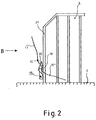
- FIG. 2 shows a particularly suitable embodiment for a clamp holder 18 for realizing the subject matter of the second patent represented.
- This clamp 18 is resiliently attached to the wall strut 21 of the partition 3.
- the clamp holder 18 is essentially formed from an elastic sheet metal strip that, however, is bent at its free end to an angled clamping tongue 20, the tip of which protrudes up to the wall strut 21, so that a slot 19 is formed between the remaining sheet metal strip and the wall strut 21 . In this area, the sheet metal strip is bent away from the wall strut 21 in order to keep the slot 19 clear.
- the start of the wire ring 10 ′ can be pressed into the slot 19 between the clamping tongue 20 and the wall strut 21, since the clamping tongue 20 can be resiliently pushed away from the wall strut 21.
- the wire ring start 10 ' is then held in the slot 19.
- the clamping tongue 20 can be resiliently pushed away from the coil start 10' by the wall strut 21, so that the result is the start of the wire ring 10 'can escape from the slot 19.
- the wire ring or rings can rest on circular plates or ring-shaped plates or other analog elements which cooperate with the weight-sensitive switch.
Landscapes
- Engineering & Computer Science (AREA)
- Quality & Reliability (AREA)
- Wire Processing (AREA)
- Unwinding Of Filamentary Materials (AREA)
- Heat Treatment Of Strip Materials And Filament Materials (AREA)
- Winding, Rewinding, Material Storage Devices (AREA)
- Guides For Winding Or Rewinding, Or Guides For Filamentary Materials (AREA)
Claims (4)
Priority Applications (1)
| Application Number | Priority Date | Filing Date | Title |
|---|---|---|---|
| AT85101602T ATE39105T1 (de) | 1984-02-17 | 1985-02-14 | Vorrichtung zum kontinuierlichen abziehen von draht. |
Applications Claiming Priority (2)
| Application Number | Priority Date | Filing Date | Title |
|---|---|---|---|
| DE3405760 | 1984-02-17 | ||
| DE3405760A DE3405760C1 (de) | 1984-02-17 | 1984-02-17 | Vorrichtung zum kontinuierlichen Abziehen von Draht |
Publications (3)
| Publication Number | Publication Date |
|---|---|
| EP0152917A2 EP0152917A2 (fr) | 1985-08-28 |
| EP0152917A3 EP0152917A3 (en) | 1987-02-04 |
| EP0152917B1 true EP0152917B1 (fr) | 1988-12-07 |
Family
ID=6228048
Family Applications (1)
| Application Number | Title | Priority Date | Filing Date |
|---|---|---|---|
| EP85101602A Expired EP0152917B1 (fr) | 1984-02-17 | 1985-02-14 | Dispositif pour le dévidage en continu de fil |
Country Status (3)
| Country | Link |
|---|---|
| EP (1) | EP0152917B1 (fr) |
| AT (1) | ATE39105T1 (fr) |
| DE (2) | DE3405760C1 (fr) |
Families Citing this family (2)
| Publication number | Priority date | Publication date | Assignee | Title |
|---|---|---|---|---|
| AT509726B1 (de) * | 2010-08-26 | 2011-11-15 | Fronius Int Gmbh | Verfahren und vorrichtung zur erfassung des gewichts eines drahtvorrats |
| CN109692886B (zh) * | 2018-12-25 | 2020-05-08 | 铜陵顶科镀锡铜线有限公司 | 一种用于多头拉丝机的感应式自动换线系统 |
Family Cites Families (5)
| Publication number | Priority date | Publication date | Assignee | Title |
|---|---|---|---|---|
| US1966532A (en) * | 1933-03-11 | 1934-07-17 | Contincntal Steel Corp | Nonrotative reel |
| DE1774713A1 (de) * | 1968-08-20 | 1971-11-04 | Reiners Walter Dr Ing | Abspulvorrichtung fuer fadenfoermiges Gut |
| CH577050A5 (fr) * | 1974-04-08 | 1976-06-30 | Rueti Ag Maschf | |
| DE3208352C2 (de) * | 1982-03-09 | 1984-09-27 | Leonische Drahtwerke AG, 8500 Nürnberg | Drahtentnahmeeinrichtung |
| FR2527661B1 (fr) * | 1982-05-26 | 1986-04-11 | Cables De Lyon Geoffroy Delore | Procede d'assistance au chargement de bobines sur une cableuse et dispositif pour la mise en oeuvre du procede |
-
1984
- 1984-02-17 DE DE3405760A patent/DE3405760C1/de not_active Expired
-
1985
- 1985-02-14 EP EP85101602A patent/EP0152917B1/fr not_active Expired
- 1985-02-14 AT AT85101602T patent/ATE39105T1/de not_active IP Right Cessation
- 1985-02-14 DE DE8585101602T patent/DE3566657D1/de not_active Expired
Also Published As
| Publication number | Publication date |
|---|---|
| DE3405760C1 (de) | 1985-05-15 |
| EP0152917A2 (fr) | 1985-08-28 |
| ATE39105T1 (de) | 1988-12-15 |
| DE3566657D1 (en) | 1989-01-12 |
| EP0152917A3 (en) | 1987-02-04 |
Similar Documents
| Publication | Publication Date | Title |
|---|---|---|
| DE2008142C3 (de) | Selbsttätige Vorrichtung zum Anspinnen bei in einer Reihe angeordneten Offen-End-Spinneinheiten nach Fadenbruch | |
| EP0084620B1 (fr) | Appareil pour cercler des balles | |
| DE1535019B1 (de) | Vorrichtung zum Abziehen von Spulen an Ringspinnmaschinen od.dgl. | |
| DE2547301C2 (fr) | ||
| EP0148419A1 (fr) | Dispositif pour réaliser un enroulement de réserve de fil | |
| DE2657694B2 (de) | Spulenwechselvorrichtung an einer Offenendspinnmaschine | |
| DE3718659C1 (de) | Warenabzugs- und -aufwickelvorrichtung fuer Rundstrickmaschinen | |
| DE2543986A1 (de) | Verfahren und vorrichtung zur sicherung einer reservewicklung auf einer spulenhuelse | |
| DE3040398C2 (de) | Verfahren zum Auswechseln eines fertigen Wickels gegen einen leeren Wickelkern in einer Doppeltragwalzenwickelmaschine sowie Vorrichtung zur Durchführung des Verfahrens | |
| DE2758064B2 (de) | Verfahren und Vorrichtung zum Beseitigen einer Unregelmäßigkeit im Faden an einer Spinnstelle einer Offen-End-Spinnvorrichtung | |
| DE2811960A1 (de) | Verfahren und vorrichtung zum individuellen anspinnen einzelner offenend- spinnvorrichtungen | |
| EP0036066B1 (fr) | Dispositif pour interrompre l'arrivée du ruban de fibres d'un dispositif à filer à bout libéré | |
| EP0162367A1 (fr) | Procédé et dispositif pour la préparation de l'extrémité de fil pour la remise en route d'une machine à bout libéré | |
| DE3405760C1 (de) | Vorrichtung zum kontinuierlichen Abziehen von Draht | |
| EP0367042A1 (fr) | Table d'alimentation double | |
| EP3566657B1 (fr) | Dispositif et procédé de coupe à longueur de matière à coudre chirurgicale | |
| AT401395B (de) | Vorrichtung zum reinigen von unterwindeflächen an spindeln von ringspinn- oder ringzwirnmaschinen | |
| EP0362545B1 (fr) | Procédé pour l'enfilage automatique et répété du fil électrode d'une machine d'électro-érosion à fil et dispositif pour sa mise en oeuvre | |
| DE4142620C2 (de) | Vorrichtung zum Abziehen von auf Transporttellern aufgesteckten Spulenhülsen | |
| CH626926A5 (fr) | ||
| CH647562A5 (de) | Vorrichtung zum einfuehren eines fadens in ein abzugswalzenpaar einer offenend-spinnmaschine und verfahren zu ihrem betrieb. | |
| DE19520153B4 (de) | Topfspinnmaschine | |
| DE1710169A1 (de) | Verfahrbarer Gatterwagen fuer Zettel- oder Schaergatter | |
| DE2455913A1 (de) | Spinnmaschine und verfahren zum spulenwechseln | |
| DE3924095C2 (fr) |
Legal Events
| Date | Code | Title | Description |
|---|---|---|---|
| PUAI | Public reference made under article 153(3) epc to a published international application that has entered the european phase |
Free format text: ORIGINAL CODE: 0009012 |
|
| AK | Designated contracting states |
Designated state(s): AT BE CH DE FR GB IT LI LU NL SE |
|
| 17P | Request for examination filed |
Effective date: 19860108 |
|
| PUAL | Search report despatched |
Free format text: ORIGINAL CODE: 0009013 |
|
| AK | Designated contracting states |
Kind code of ref document: A3 Designated state(s): AT BE CH DE FR GB IT LI LU NL SE |
|
| 17Q | First examination report despatched |
Effective date: 19871028 |
|
| GRAA | (expected) grant |
Free format text: ORIGINAL CODE: 0009210 |
|
| AK | Designated contracting states |
Kind code of ref document: B1 Designated state(s): AT BE CH DE FR GB IT LI LU NL SE |
|
| REF | Corresponds to: |
Ref document number: 39105 Country of ref document: AT Date of ref document: 19881215 Kind code of ref document: T |
|
| GBT | Gb: translation of ep patent filed (gb section 77(6)(a)/1977) | ||
| REF | Corresponds to: |
Ref document number: 3566657 Country of ref document: DE Date of ref document: 19890112 |
|
| ET | Fr: translation filed | ||
| ITF | It: translation for a ep patent filed | ||
| PLBE | No opposition filed within time limit |
Free format text: ORIGINAL CODE: 0009261 |
|
| STAA | Information on the status of an ep patent application or granted ep patent |
Free format text: STATUS: NO OPPOSITION FILED WITHIN TIME LIMIT |
|
| 26N | No opposition filed | ||
| ITTA | It: last paid annual fee | ||
| PGFP | Annual fee paid to national office [announced via postgrant information from national office to epo] |
Ref country code: LU Payment date: 19920122 Year of fee payment: 8 |
|
| PGFP | Annual fee paid to national office [announced via postgrant information from national office to epo] |
Ref country code: DE Payment date: 19920127 Year of fee payment: 8 |
|
| PGFP | Annual fee paid to national office [announced via postgrant information from national office to epo] |
Ref country code: GB Payment date: 19920207 Year of fee payment: 8 |
|
| PGFP | Annual fee paid to national office [announced via postgrant information from national office to epo] |
Ref country code: CH Payment date: 19920211 Year of fee payment: 8 |
|
| PGFP | Annual fee paid to national office [announced via postgrant information from national office to epo] |
Ref country code: AT Payment date: 19920213 Year of fee payment: 8 |
|
| PGFP | Annual fee paid to national office [announced via postgrant information from national office to epo] |
Ref country code: SE Payment date: 19920217 Year of fee payment: 8 |
|
| PGFP | Annual fee paid to national office [announced via postgrant information from national office to epo] |
Ref country code: BE Payment date: 19920218 Year of fee payment: 8 |
|
| PGFP | Annual fee paid to national office [announced via postgrant information from national office to epo] |
Ref country code: FR Payment date: 19920224 Year of fee payment: 8 |
|
| PGFP | Annual fee paid to national office [announced via postgrant information from national office to epo] |
Ref country code: NL Payment date: 19920229 Year of fee payment: 8 |
|
| EPTA | Lu: last paid annual fee | ||
| PG25 | Lapsed in a contracting state [announced via postgrant information from national office to epo] |
Ref country code: LU Free format text: LAPSE BECAUSE OF NON-PAYMENT OF DUE FEES Effective date: 19930214 Ref country code: GB Effective date: 19930214 Ref country code: AT Effective date: 19930214 |
|
| PG25 | Lapsed in a contracting state [announced via postgrant information from national office to epo] |
Ref country code: SE Effective date: 19930215 |
|
| PG25 | Lapsed in a contracting state [announced via postgrant information from national office to epo] |
Ref country code: LI Effective date: 19930228 Ref country code: CH Effective date: 19930228 Ref country code: BE Effective date: 19930228 |
|
| BERE | Be: lapsed |
Owner name: LUDWIG ROLAND Effective date: 19930228 |
|
| PG25 | Lapsed in a contracting state [announced via postgrant information from national office to epo] |
Ref country code: NL Effective date: 19930901 |
|
| GBPC | Gb: european patent ceased through non-payment of renewal fee |
Effective date: 19930214 |
|
| NLV4 | Nl: lapsed or anulled due to non-payment of the annual fee | ||
| PG25 | Lapsed in a contracting state [announced via postgrant information from national office to epo] |
Ref country code: FR Effective date: 19931029 |
|
| REG | Reference to a national code |
Ref country code: CH Ref legal event code: PL |
|
| PG25 | Lapsed in a contracting state [announced via postgrant information from national office to epo] |
Ref country code: DE Effective date: 19931103 |
|
| REG | Reference to a national code |
Ref country code: FR Ref legal event code: ST |
|
| EUG | Se: european patent has lapsed |
Ref document number: 85101602.2 Effective date: 19930912 |