EP0152933A2 - Electron gun - Google Patents
Electron gun Download PDFInfo
- Publication number
- EP0152933A2 EP0152933A2 EP85101706A EP85101706A EP0152933A2 EP 0152933 A2 EP0152933 A2 EP 0152933A2 EP 85101706 A EP85101706 A EP 85101706A EP 85101706 A EP85101706 A EP 85101706A EP 0152933 A2 EP0152933 A2 EP 0152933A2
- Authority
- EP
- European Patent Office
- Prior art keywords
- electrodes
- auxiliary electrode
- electron
- electron gun
- electrode
- Prior art date
- Legal status (The legal status is an assumption and is not a legal conclusion. Google has not performed a legal analysis and makes no representation as to the accuracy of the status listed.)
- Granted
Links
Images






Classifications
-
- H—ELECTRICITY
- H01—ELECTRIC ELEMENTS
- H01J—ELECTRIC DISCHARGE TUBES OR DISCHARGE LAMPS
- H01J29/00—Details of cathode-ray tubes or of electron-beam tubes of the types covered by group H01J31/00
- H01J29/46—Arrangements of electrodes and associated parts for generating or controlling the ray or beam, e.g. electron-optical arrangement
- H01J29/48—Electron guns
- H01J29/50—Electron guns two or more guns in a single vacuum space, e.g. for plural-ray tube
- H01J29/503—Three or more guns, the axes of which lay in a common plane
-
- H—ELECTRICITY
- H01—ELECTRIC ELEMENTS
- H01J—ELECTRIC DISCHARGE TUBES OR DISCHARGE LAMPS
- H01J2229/00—Details of cathode ray tubes or electron beam tubes
- H01J2229/48—Electron guns
- H01J2229/4844—Electron guns characterised by beam passing apertures or combinations
- H01J2229/4848—Aperture shape as viewed along beam axis
- H01J2229/4858—Aperture shape as viewed along beam axis parallelogram
- H01J2229/4865—Aperture shape as viewed along beam axis parallelogram rectangle
- H01J2229/4868—Aperture shape as viewed along beam axis parallelogram rectangle with rounded end or ends
-
- H—ELECTRICITY
- H01—ELECTRIC ELEMENTS
- H01J—ELECTRIC DISCHARGE TUBES OR DISCHARGE LAMPS
- H01J2229/00—Details of cathode ray tubes or electron beam tubes
- H01J2229/48—Electron guns
- H01J2229/4844—Electron guns characterised by beam passing apertures or combinations
- H01J2229/4848—Aperture shape as viewed along beam axis
- H01J2229/4872—Aperture shape as viewed along beam axis circular
-
- H—ELECTRICITY
- H01—ELECTRIC ELEMENTS
- H01J—ELECTRIC DISCHARGE TUBES OR DISCHARGE LAMPS
- H01J2229/00—Details of cathode ray tubes or electron beam tubes
- H01J2229/48—Electron guns
- H01J2229/4844—Electron guns characterised by beam passing apertures or combinations
- H01J2229/4848—Aperture shape as viewed along beam axis
- H01J2229/4875—Aperture shape as viewed along beam axis oval
-
- H—ELECTRICITY
- H01—ELECTRIC ELEMENTS
- H01J—ELECTRIC DISCHARGE TUBES OR DISCHARGE LAMPS
- H01J2229/00—Details of cathode ray tubes or electron beam tubes
- H01J2229/48—Electron guns
- H01J2229/4844—Electron guns characterised by beam passing apertures or combinations
- H01J2229/4848—Aperture shape as viewed along beam axis
- H01J2229/4879—Aperture shape as viewed along beam axis non-symmetric about field scanning axis
-
- H—ELECTRICITY
- H01—ELECTRIC ELEMENTS
- H01J—ELECTRIC DISCHARGE TUBES OR DISCHARGE LAMPS
- H01J2229/00—Details of cathode ray tubes or electron beam tubes
- H01J2229/48—Electron guns
- H01J2229/4844—Electron guns characterised by beam passing apertures or combinations
- H01J2229/4848—Aperture shape as viewed along beam axis
- H01J2229/4896—Aperture shape as viewed along beam axis complex and not provided for
-
- H—ELECTRICITY
- H01—ELECTRIC ELEMENTS
- H01J—ELECTRIC DISCHARGE TUBES OR DISCHARGE LAMPS
- H01J2229/00—Details of cathode ray tubes or electron beam tubes
- H01J2229/96—Circuit elements other than coils, reactors or the like, associated with the tube
- H01J2229/966—Circuit elements other than coils, reactors or the like, associated with the tube associated with the gun structure
Definitions
- the present invention relates to an electron gun for a cathode-ray tube, and more specifically to an electron lens of an electron gun for focusing at least one electron beam, preferably two or more electron beams.
- a cathode-ray tube includes at least one electron gun.
- the electron gun comprises a beam forming section for producing an electron beam and a main lens section for focusing the electron beam on the target.
- the spot diameter on the target should preferably be minimized, depending on the performance of the electron gun. Improvement of the performance of the main lens section is an effective measure for improving the performance of the electron gun.
- the main lens section is chiefly composed of an electrostatic electron lens.
- a plurality of electrodes each having an aperture are coaxially arranged so as to be applied with predetermined voltages.
- the lens performance is expected to be improved by the use of a long-focus lens which can produce, without extension of the separation distance of the electrodes, an effect equivalent to that obtained with use of a longer separation distance.
- electrostatic electron lenses for such a cathode-ray tube, including "distributed Einzel lens” disclosed in U.S. Pat. No. 3,895,253 by Schwartz et al., "tripotential lens” disclosed in U.S. Pat. No. 3,995,194 by Blacker et al., "multi-element bipotential lens” disclosed in U.S. Pat. No. 3,932,786 by Campbell, and "single-element bipotential lens” disclosed in U.S.
- the multi-element bipotential lens disclosed in U.S. Pat. No. 3,932,786 is proposed.
- resistors arranged near the individual electrodes are small.
- the electron gun of this type is unfit for practical use.
- the voltages of the electrodes are picked up at narrower intervals from the small resistor, the construction and manufacture of the electron gun are complicated.
- the small gaps between the electrodes facilitate the flow of leakage current between the electrodes.
- undesired current is produced by the leakage current, beam impact hit on the electrodes and other factors, resulting in a change of electrode potential and lowering the lens performance.
- electron guns of the following types are conventionally proposed.
- an electron gun for color picture tube disclosed in Japanese Patent Application Disclosure No. 124933/80
- three electron lenses are formed overlapping one another.
- apertures of electrodes are conical.
- projections are formed around three apertures.
- the diameter of each electron lens is increased, so that the lens performance is improved in some measure.
- the separation distance of the electrodes need be increased. This separation distance cannot, however, be increased, since it is influenced by undesired electrostatic fields in the neck.
- the object of the present invention is to provide an electron gun for cathode-ray tube improved in the performance of an electron lens, especially of a main lens section, simple in construction, and easy to manufacture.
- an electron gun for producing and directing at least one electron beam along a beam path, which comprises beam forming means and main lens means for focusing the electron beam.
- the main lens means includes first and second electrodes arranged along the beam path and having an aperture through which the electron beam is passed, and at least one auxiliary electrode means which is located between the first and second electrodes.
- the auxiliary electrode means includes at least one auxiliary electrode, the auxiliary electrode having an aperture through which the electron beam is passed, the aperture of the auxiliary electrode being greater than each of the apertures of the first and second electrodes.
- the electron gun further comprises voltage applying means for respectively applying first, second and auxiliary voltages to the first, second and auxiliary electrodes, the first and second voltages being of different levels. An electrostatic field is formed between the first and second electrodes.
- the auxiliary voltage is higher than the lower one of the first and second voltages and is lower than the higher one.
- a long-focus lens equivalent to one which may be obtained by increasing the distance between the first and second electrodes is formed between the first and second electrodes.
- FIG. 1 An electron gun according to one embodiment of the present invention applied to a color picture tube will now be described in detail.
- Figs. 1, 2 and 3 there is shown an in-line electron gun 1.
- direction X is a direction parallel to the in-line direction of the electron gun 1
- direction Y is a direction perpendicular to both direction X and the tube axis
- direction Z is a direction in which the tube axis extends and which is perpendicular to both directions X and Y.
- Fig. 2 is a sectional view of the electron gun 1 taken along a plane containing directions Y and Z
- Fig. 3 is a sectional view of the electron gun 1 taken along a plane containing directions X and Z.
- Figs. 1 As shown in Figs.
- the electron gun 1 comprises a plurality of electrodes and an insulating support means 2 for supporting the electrodes.
- the electrodes include cathodes 9a, 9b and 9c arranged in line, first, second, third and fourth grids 11, 12, 13 and 14, a convergence electrode 15, and an auxiliary electrode 16 disposed between the third and fourth grids 13 and 14 and greater in size than the same.
- Three heaters 6a, 6b and 6c for generating three electron beams 3a, 3b and 3c are arranged in the cathodes 9a, 9b and 9c, respectively.
- the three electron beams 3a, 3b and 3c generated by the heaters 6a, 6b and 6c in the cathodes 9a, 9b and 9c are passed through the electrodes 11, 12, 13, 16, 14 and 15, and caused to hit against red, green and blue phosphor layers (not shown) of a fluorescent screen as a target.
- the grids 11 to 15 and the convergence electrode 16 have apertures for passing through the electron beams as mentioned later and are unitized.
- the electron gun 1 is formed of two fundamental sections; a crossover spot forming section, which includes a beam forming region, consisting of the cathodes 9 and the first and second grids 11 and 12 and forms a crossover spot, and an accelerating and focusing lens section for focusing electron beams on the screen.
- the crossover spot forming section may also be referred to as a four-pole section, which consists of the cathodes 9 and the first, second, and third grids 11, 12 and 13.
- the accelerating and focusing lens section is normally referred to as a main lens section, which consists of the third and fourth grids 13 and 14.
- the third grid 13 is used in common in the four-pole section and the main lens section.
- the first and second grids 11 and 12 are planar in shape and arranged in close vicinity to each other.
- the third grid 13, which is located close to the second grid 12, is formed of two bathtub-shaped electrodes 23a and 23b which are joined together.
- the fourth grid 14, which is located at a predetermined distance from the third grid 13, is also formed of two bathtub-shaped electrodes 24a and 24b which are joined together.
- the convergence electrode 15 is formed of a single cup-shaped electrode 25a which is welded to the fourth grid 14.
- Each three apertures are aligned with their adjoining counterparts so as to be arranged along the paths of the individual electron beams.
- the apertures of the first and second grids 11 and 12 are relatively narrow, and the apertures 33a, 33b and 33c of the third grid 13 on the side facing the second grid 12 are greater than those of the first and second grids 11 and 12.
- the apertures 43a, 43b and 43c of the third grid 13 on the side facing the fourth grid 14, which are relatively wide, are equal in diameter to the apertures 34a, 34b and 34c of the fourth grid 14 on the side facing the third grid 13.
- the apertures 35a, 35b and 35c of the convergence electrode 15 are narrower than the 43a, 43b and 43c of the third grid 13 and the apertures 34a, 34b and 34c of the fourth grid 14.
- Control members which are known, for example, by Japanese Patent Disclosure No. 26208/1976, are provided near the apertures 44a and 44c of the convergence electrode 15.
- the auxiliary electrode 16 is formed of two bathtub-shaped electrodes 26a and 26b, and oval shaped apertures 36 and 46 are formed in the bottom faces of the bathtub-shaped electrodes 26a and 26b, respectively.
- Fig. 4 shows a typical example of the bathtub-shaped electrode 26a of the auxiliary electrode 16
- Fig. 5 shows the bathtub-shaped electrode 23b of the third grid 13.
- the length DX of the aperture 36 of the auxiliary electrode 16 in direction X is greater than the distance dx covered by the apertures 43a, 43b and 43c of the third grid 13 arranged in a row in direction X.
- the width DY of the aperture 36 in direction Y is greater than the Y-direction diameter dy of each of the apertures 43a, 43b and 43c.
- a bulb spacer 17 is attached to the outer periphery of the convergence electrode 15.
- the bulb spacer 17 is supplied with a voltage as high as about 25 kV which is applied to an anode terminal (not shown).
- the electron gun 1 constructed in this manner is sealed in a small cylindrical neck 18 which is formed of glass.
- a number of stem pins 19 are arranged on the left-hand end (Fig. 1) of the neck 18. The stem pins 19 support the electron gun 1, and voltages for the first to third grids 11, 12 and 13 except for the fourth grid 14 and the convergence electrode 15 are externally applied through the stem pins 19.
- the electrodes arranged in the aforesaid manner are supplied with voltages as follows.
- a cut-off voltage of about 150 V is held on the cathodes 9, and a modulation signal is added to the cut-off voltage.
- the first grid 11 is grounded, while voltages of about 700 V and 6.5 kV are applied to the second third grids 12 and 13, respectively.
- a high anode voltage of about 25 kV is applied to the fourth grid 14, and a voltage intermediate between those of the third and fourth grids 13 and 14 is applied to the auxiliary electrode 16.
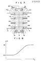
- Figs. 6 and 7 show an equipotential distribution of an electron lens in the main lens section with the above-described electrode arrangement.
- Figs. 6 and 7 correspond to Figs. 2 and 3, respectively.
- regions between the apertures 43a, 43b and 43c of the third grid 13 and the apertures 34a, 34b and 34c of the fourth grid 4, as indicated by broken lines, define the diameter of the electron lens.
- Numeral 20 designates equipotential lines. In the regions indicated by broken lines, the equipotential distribution is rarely disturbed. In these regions, moreover, the equipotential distribution is equivalent to that obtained when the separation distance between the third and fourth grids 13 and 14 is wide, and there is no influence of any ambient electrostatic fields.
- Fig. 1 show an equipotential distribution of an electron lens in the main lens section with the above-described electrode arrangement.
- Figs. 6 and 7 correspond to Figs. 2 and 3, respectively.
- FIG. 8 shows an axial potential distribution along line VIII-VIII of Fig. 6.
- the axial potential distribution varies considerably gradually in direction Z.
- the electrooptical magnification and the coefficient of spherical aberration of the electron lens are reduced, so that the performance of the electron lens is greatly improved.
- auxiliary electrode 16 is disposed between the third and fourth grids 13 and 14.
- the auxiliary electrode 16 has an aperture diameter greater than the diameter of the electron lens, that is, the aperture diameter of the third and fourth grids 13 and 14.
- the voltage intermediate between those of the third and fourth grids 13 and 14 is applied to the auxiliary electrode 16. Accordingly, undesired electrostatic fields in the neck 18 are cut off, so that the essential electrostatic field for the electron lens will never be disturbed.
- the electron lens according to the present invention can obtain the same high performance as the type in which the distance between two electrodes is merely increased.
- the auxiliary electrode 16 requires only a single aperture, as compared with the three apertures for each of the other electrodes 11 to 15.
- the electron lens can improve its performance without changing the distances between the respective centers of the three apertures of the other electrodes 11 to 15.
- the sizes of the apertures 36, 46 of the auxiliary electrode 16 must increasingly be wider than the sizes of the apertures 43a, 43b, 43c, 34a, 34b and 34c of the third and fourth grids 13 and 14 as the distance between the third and fourth grids 13 and 14 becomes greater. If the sizes of apertures 36, 46 of the auxiliary electrode 16 is not great enough, the electric field of the electron lens between the third and fourth grids 13 and 14 is disturbed by the potential of the auxiliary electrode 16, so that the beam spot on the target is distorted. This distortion of the beam spot can be corrected by adjusting the potential, position, and aperture shape of the auxiliary electrode 16.
- the sizes of the aperture 36, 46 of the auxiliary electrode 16 are not sufficiently large in both directions X and Y, two substantial quadrupole lenses are formed in the regions between the three circular apertures 43a, 43b and 43c of the third grid 13 and the one bathtub-shaped aperture 36 of the auxiliary electrode 16 and between the apertures 34a, 34b and 34c of the fourth grid 14 and the other bathtub-shaped aperture 46 of the auxiliary electrode 16. Since the directions in which the electron beams converge or driverge at these quadrupole lenses are opposite to each other, the direction of distortion of the beam spot varies with the voltage of the auxiliary electrode 16. If the voltage of the auxiliary electrode 16 is too low or too high, the shape of the beam spot is horizontally or vertically elongated.
- the beam spot is circular. This proper voltage is a little lower than the voltage intermediate between the respective potential of the third and fourth grids 13 and 14. The reason is that lens forces acting on the electron beams are different due to the differences in speed and diameter between the electron beams in the quadrupole lenses, although the directions of the quadrupole lenses act in the opposite direction to the electron lens.
- the distortion of the beam may be corrected by changing the shape of the aperture 36 or 46 of the auxiliary electrode 16.
- the beam distortion may be corrected by adjusting the position of the auxiliary electrode 16, that is, the distances between the third grid 13 and the auxiliary electrode 16 and between the fourth grid 14 and the auxiliary electrode 16.
- this correction may be performed in any other region than the region of the auxiliary electrode 16.
- the electron beam may have astigmatism at the beam generating section so that the astigmatism is canceled in the region of the auxiliary electrode 16.
- the electron gun 1 In a color picture tube, the electron gun 1 must converge the three electron beams on a common point on the target, i.e., a mask or screen. This may be achieved by several methods, including a method in which electron guns on either side are inclined relatively to a central one, a method in which main lens sections or other electron lens sections on either side are inclined relatively to a main lens section or other electron lens section in the center, and a method in which asymmetrical lenses are formed at main lens sections or other electron lens sections on either side. These methods may be directly applied to the present invention. According to the present invention, moreover, the three electron beams can also be converged on a common point on the target through the region of the auxiliary electrode 16.
- a second embodiment of the auxiliary electrode will be described.
- like reference numerals are used to designate like portions as included in the first embodiment shown in Figs. 1 to 3.
- the X-direction diameter DX4 of an auxiliary electrode 126b on the side of the fourth grid 14 is shorter than the X-direction diameter DX3 of an auxiliary electrode 126a on the side of the third grid 13.
- the electron beams 3a and 3c on either side are slightly deflected toward the central electron beam 3b, so that the three electron beams 3a, 3b and 3c are converged on the target.
- the potential of the auxiliary electrode 126b on the side of the fourth grid 14, on a cross section taken along plane X-Z, has a greater influence on the electron lens than the potential of the auxiliary electrode 126a on the side of the third grid 13, and the former is lower than an average potential in the region, so that the electron beams 3a and 3c are subjected to an inward force.
- Figs. 11 and 12 show a third embodiment different from the auxiliary electrode 116 shown in Figs. 9 and 10.
- the electron gun 1 of this embodiment includes two separated auxiliary electrodes 226a and 226b.
- the potentials of the auxiliary electrodes 226a and 226b are intermediate between those of the third and fourth grids 13 and 14.
- the potential of the auxiliary electrode 226b on the side of the fourth grid 14 is a little lower than that of the auxiliary electrode 226a on the side of the third grid 13.
- the three electron beams 3a, 3b and 3c are converged on the target.
- the convergence may be adjusted by suitably changing the length of the two auxiliary electrodes 226a and 226b.
- the voltages of the auxiliary electrodes 16, 116 and 226 are externally applied through the stem pins 19. According to the present invention, however, these voltages may be applied by dividing resistances.
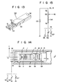
- Figs. 13, 14 and 15 show an example of a resistor 54 subjected to resistance division, embodied in the first embodiment.
- the resistor 54 includes a thin substrate 50 formed of ceramics, and a resistive material 51 and terminal portions 52 are arranged on the substrate 50.
- the resistive material 51 is mainly formed of an oxide compound based on palladium or ruthenium, especially a mixture of ruthenium oxide and glass.
- Fig. 14 is an electric circuit diagram showing the resistor 54.
- a high anode voltage Eb is divided by the resistor 54, and divided voltage is applied to the auxiliary electrode 16.
- the resistor 54 is in the form of a plate. According to the present invention, however, the resistor 54 may be divided in two by the terminal portion 52 connected to the auxiliary electrode 16, or may be formed of a number of resistors. Alternatively, the resistor 54 may be formed by applying the resistive material 51 directly to the outer lateral face of the insulating support frame 2. Naturally, the insulating support means 2 may itself be used as the resistor 54.
- the terminal portion 52 at one end of the resistor 54 is connected to one of the stem pins 19.
- this one-end terminal portion 52 may be connected to the third grid 13 or other grid.
- another terminal portion 52 may be provided between the terminal portion 52 at the one end and the terminal portion 52 connected to the auxiliary electrode 16 so that the fourth terminal portion 52 is connected to the third grid 13.
- the voltage divided by the resistive body 54 is applied to the third grid 13.
- part of the high anode voltage divided by the resistor 54 is applied to the auxiliary electrode 16. Accordingly, it is unnecessary to apply middle or high voltage to the auxiliary electrode 16 through the stem pins 19, so that the voltage-withstand property of the bottom part of the neck portion including the stem pins 19 is improved. Thus, the cathode-ray tube can be offered with high practicability. Also, voltage of the third grid 13 is applied by dividing the resistance of the resistor 54, so that the voltage-withstand property of the neck portion is improved. The convergence of the electron lens can be adjusted to some degree with ease, since the voltage of the third grid 13 can be controlled with a low voltage through the stem pins 19.
- the high anode voltage is lowered substantially to the ground voltage level through the resistor 54 with high resistance, so that undesired spark current produced in the cathode-ray tube can greatly be reduced, and transistors, ICs and other devices arranged out of the cathode-ray tube can be protected against the spark current in the cathode-ray tube.
- the resistor 54 may be made considerably greater in size than a conventional one. Further, the resistor 54 can readily be attached to the electrode support means 2, and the manufacture of the electron gun 1 is very easy. Since the distance across the auxiliary electrode 16 is long, leak current cannot easily flow through the auxiliary electrode 16. Therefore, it is easy to adjust the convergence force of the electron beams 3a, 3b and 3c in directions X and Y and the shape of these beam.
- the electron gun 1 does not always require a number of electrodes and a number of voltages to be applied thereto.
- Use of a single electrode and a single voltage therefor ensures the same effect of the electron lens as is obtained with use of a number of electrodes and voltages.
- the middle voltage to be applied to the auxiliary electrode 16 need not always be obtained by dividing the resistance of the resistor 54, and may also be obtained through one of the stem pins 19.
- the auxiliary electrodes 16, 116 and 216 are disposed between the third and fourth grids 13 and 14 at predetermined distances therefrom. According to the present invention, however, each of the auxiliary electrodes 16, 116, 216 may partially cover one or both of the third and fourth grids 13 and 14.
- Fig. 17 shows an embodiment in which an auxiliary electrode 316 partially covers both the third and fourth grids 13 and 14. In this embodiment, the auxiliary electrode 316 and the third and fourth grids 13 and 14 overlap one another with gaps between them in the radial direction of the neck, so that the influences of undesired electrostatic fields generated from the inner wall of the neck are eliminated thoroughly. Thus, it is possible to completely prevent a change on standing of convergence due to electric charges of the inner wall of the neck which constitutes a drawback of a prior art color picture tube.
- each of a pair of insulating support frames 402 may be divided into two subframes 402a and 402b so that the auxiliary electrode 416 is interposed between them.
- This division of the support frames 402 allows the auxiliary electrode 416 to be maximized in radial size within the inner wall of the neck.
- the separation distance of the third and fourth grids 13 and 14 can be increased.
- the electron lens can be improved in performance, and the distortion of the beam spot can be adjusted with ease.
- Figs. 19 and 20 are sectional views of the electron gun 1 of Fig. 18 taken along planes Y-Z and X-Z, respectively.
- Fig. 21 shows one of a pair of components 426a and 426b of the auxiliary electrode 416 of the electron gun 1.
- Fig. 22 shows a modified example of the resistor in which two resistor elements 454a and 454b are arranged in the electron gun 1. The voltage of the auxiliary electrode 416 is obtained by dividing a high anode voltage by means of the resistor elements 454a and 454b.
- FIG. 23 to 27 there will be described various embodiments of the electron gun 1 of the present invention which also are applied to a color picture tube and improved for greater aperture of the electron lens.
- third and fourth grids 513 and 514 are so designed that the aperture of the electron lens is greater on their front side.
- wide apertures 543 and 534 are formed in the bottom face portions of a bathtub-electrode 523b of the third grid 513 on the side facing the fourth grid 514 and a bathtub-shaped electrode 524a of the fourth grid 514 on the side facing the third grid 513,.respectively.
- Fig. 23 wide apertures 543 and 534 are formed in the bottom face portions of a bathtub-electrode 523b of the third grid 513 on the side facing the fourth grid 514 and a bathtub-shaped electrode 524a of the fourth grid 514 on the side facing the third grid 513,.respectively.
- FIG. 25 shows the bathtub-shaped electrode 523b of the third grid 513 on the side facing the fourth grid 514.
- the apertures 543 and 534 are each defined by three circular apertures overlapping one another.
- the bathtub-shaped electrode 523b is fitted with planar electrodes 501 and 502 in positions recessed from the bottom face portions of the electrode 523b.
- the bathtub-shaped electrode 524a is fitted with planar electrodes 503 and 504. With this electrode arrangement, three electron lenses formed of the third and fourth grids 513 and 514 overlap one another. Thus, these electron lenses have a lens aperture which is wide in the optical sense.
- the auxiliary electrode 16 formed of two bathtub-shaped electrodes is interposed between the third and fourth grids 513 and 514.
- the electron lens has a long separation distance of the electrodes, as in the first to fifth embodiments, and has a distance optically greater than the lenses of the first to fifth embodiments. Therefore, it produces more distingushed effects.
- Figs. 26 and 27 show modified examples of the bathtub-shaped electrode 523b of the third grid 513 on the side facing the fourth grid 514.
- a bathtub-shaped electrode 623b shown in Fig. 26 has three conical apertures 643a, 643b and 643c spreading with the advance of the electron beams. These apertures 643a, 643b and 643c overlap one another at the bottom.
- the bottom portion of a bathtub-shaped electrode 723b shown in Fig. 27 includes a peripheral rim 701 and a bottom face 702 recessed from the peripheral rim 701. Three apertures 743a, 743b and 743c are formed in the bottom face 702.
- the bathtub-shaped electrode 623b and 723b shown in Figs. 26 and 27 ensure a wide lens aperture for the electron lens of the main lens section.
- the configurations of the bathtub-shaped electrodes 623b and 723b shown in Figs. 26 and 27 may suitably be applied to the bathtub-shaped electrode of the fourth grid 514 on the side facing the third grid 513.
- the construction of the electron lens is based on a bipotential lens which is formed of the third and fourth grids.
- the auxiliary electrode is disposed between the two grids, and has wide apertures.
- the fundamental construction of the electron lens may be of a unipotential, quadripotential or periodic-potential type, as shown in Fig. 28, 29 or 30. Alternatively, it may be of a tripotential type (not shown).
- a number of auxiliary electrodes 616, 716 and 816 are arranged throughout the regions forming electon lenses of those various types.
- auxiliary electrodes 616, 716 and 816 may be arranged in only a main electron lens region without all the electron lens regions.
- a voltage Ec3 of the third grid 13 may be set to about 8 to 9 kV, so that the electron beams scattered from the crossover spot forming region can be used in the best condition at the main lens section.
- three electron guns are arranged in line with one another. According to the present invention, however, three electron guns may be arranged in a delta, or a greater number of electron guns may be arranged in a suitable manner. Also, the present invention may be applied to a cathode-ray tube using a single electron gun.
Landscapes
- Electrodes For Cathode-Ray Tubes (AREA)
Abstract
Description
- The present invention relates to an electron gun for a cathode-ray tube, and more specifically to an electron lens of an electron gun for focusing at least one electron beam, preferably two or more electron beams.
- Conventionally, a cathode-ray tube includes at least one electron gun. The electron gun comprises a beam forming section for producing an electron beam and a main lens section for focusing the electron beam on the target. As a very important factor to determine the performance of the cathode-ray tube, there is the spot diameter of the electron beam on the target. The spot diameter on the target should preferably be minimized, depending on the performance of the electron gun. Improvement of the performance of the main lens section is an effective measure for improving the performance of the electron gun.
- The main lens section is chiefly composed of an electrostatic electron lens. In the electron lens region, a plurality of electrodes each having an aperture are coaxially arranged so as to be applied with predetermined voltages. There may be several types of such electrostatic electron lenses, according to the variety of voltage. For higher performance of the main lens section, however, it is necessary to increase the size of the aperture thereby increasing the lens aperture in the optical sense, or to lengthen the separation distance of the electrodes to cause a gradual potential change in the region around the electrodes, thereby forming a long-focus lens having a long focal length.
- However, such a prior art electron gun for cathode-ray tube is sealed in a cylindrical glass tube, i.e., the neck portion of a cathode-ray tube. Therefore, the size of aperture of the electrodes or the lens diameter is practically restricted by the diameter of the cylindrical glass tube. Also, the separation distance of the electrodes is limited, so that an electrostatic focusing field formed between the electrodes may not be influenced by any other undesired electric fields in the cylindrical glass tube. In a color picture tube, in particular, if a plurality of electron guns are arranged in line, narrower intervals between the electron guns will make it easier to converge a plurality of electron beams on the same point in the whole surface of a screen. In consideration of deflection, moreover, the narrow intervals between the electron guns improve the economy of electric power. The narrower intervals require further reduction in size of the apertures of the electrodes.
- In the cathode-ray tube as described above, the lens performance is expected to be improved by the use of a long-focus lens which can produce, without extension of the separation distance of the electrodes, an effect equivalent to that obtained with use of a longer separation distance. There are proposed several electrostatic electron lenses for such a cathode-ray tube, including "distributed Einzel lens" disclosed in U.S. Pat. No. 3,895,253 by Schwartz et al., "tripotential lens" disclosed in U.S. Pat. No. 3,995,194 by Blacker et al., "multi-element bipotential lens" disclosed in U.S. Pat. No. 3,932,786 by Campbell, and "single-element bipotential lens" disclosed in U.S. Pat. No. 4,124,810 by Bortfeld et al. Among these lenses, the distributed Einzel lens disclosed in U.S. Pat. No. 3,895,253 is not practical because, in this lens, electric discharge is liable to be caused between the relatively low voltage of the beam forming section and the higher anode voltage at the main lens section nearest thereto.
- In the tripotential lens disclosed in U.S. Pat. No. 3,995,194 and the single-element bipotential lens disclosed in U.S. Pat. No. 4,124,810, three cylindrical electrodes with the same diameter are arranged along electron beams for low, middle, and high voltages, so that a gradual potential change is produced at the main lens section. An optimum lens performance may be obtained if the length of the middle- voltage electrode is substantially equal to the radius of the electrode aperture. Thus, the lens performance cannot further be improved.
- For additional improvement of the lens performance, therefore, the multi-element bipotential lens disclosed in U.S. Pat. No. 3,932,786 is proposed. In an electron gun using this lens, however, resistors arranged near the individual electrodes are small. Thus, the electron gun of this type is unfit for practical use. Moreover, since the voltages of the electrodes are picked up at narrower intervals from the small resistor, the construction and manufacture of the electron gun are complicated. The small gaps between the electrodes facilitate the flow of leakage current between the electrodes. In consequence, undesired current is produced by the leakage current, beam impact hit on the electrodes and other factors, resulting in a change of electrode potential and lowering the lens performance. These drawbacks make it very hard to put the electron gun of this type to practical use.
- To increase the diameter of the electron lens, moreover, electron guns of the following types are conventionally proposed. In an electron gun for color picture tube disclosed in Japanese Patent Application Disclosure No. 124933/80, three electron lenses are formed overlapping one another. In another electron gun stated in Proceedings of the third international display research conference, Japan display 1983, pp. 268 through 271, apertures of electrodes are conical. In an electron gun disclosed in Japanese Patent Application Disclosure No. 103246/82, moreover, projections are formed around three apertures. In these electron guns, the diameter of each electron lens is increased, so that the lens performance is improved in some measure. For further improved lens performance, the separation distance of the electrodes need be increased. This separation distance cannot, however, be increased, since it is influenced by undesired electrostatic fields in the neck.
- The object of the present invention is to provide an electron gun for cathode-ray tube improved in the performance of an electron lens, especially of a main lens section, simple in construction, and easy to manufacture.
- According to the present invention, there is provided an electron gun for producing and directing at least one electron beam along a beam path, which comprises beam forming means and main lens means for focusing the electron beam. The main lens means includes first and second electrodes arranged along the beam path and having an aperture through which the electron beam is passed, and at least one auxiliary electrode means which is located between the first and second electrodes. The auxiliary electrode means includes at least one auxiliary electrode, the auxiliary electrode having an aperture through which the electron beam is passed, the aperture of the auxiliary electrode being greater than each of the apertures of the first and second electrodes. The electron gun further comprises voltage applying means for respectively applying first, second and auxiliary voltages to the first, second and auxiliary electrodes, the first and second voltages being of different levels. An electrostatic field is formed between the first and second electrodes. The auxiliary voltage is higher than the lower one of the first and second voltages and is lower than the higher one.
- In the electron gun with the construction described above, a long-focus lens equivalent to one which may be obtained by increasing the distance between the first and second electrodes is formed between the first and second electrodes.
- This invention can be more fully understood from the following detailed description when taken in conjunction with the accompanying drawings, in which:
- Fig. 1 is a schematic side view of an electron gun according to one embodiment of the present invention applied to a color picture tube, showing the electron gun along its tube axis;
- Fig. 2 is a schematic sectional view of the principal part of the electron gun of Fig. 1 taken along a plane perpendicular to a plane containing the tube axis and three electron beams;
- Fig. 3 is a schematic sectional view of the principal part of the electron gun of Fig. 1 taken along the plane containing the tube axis and the three electron beams;
- Figs. 4 and 5 are perspective views showing components of an auxiliary electrode and a first grid, respectively, used in the embodiment of Fig. 1;
- Figs. 6 and 7 show an equipotential line distribution for illustrating an electrostatic electron lens of the invention;
- Fig. 8 shows a curve representing potential on the axis of the electron lens indicated by line VIII-VIII in Fig. 6;
- Figs. 9 to 12 are schematic sectional views showing modified examples of the auxiliary electrode of the electron gun of Fig. 1, in which Figs. 9 and 11 correspond to Fig. 2 and Figs. 10 and 12 correspond to Fig. 3;
- Fig. 13 is a cutaway perspective view showing a resistor used in the embodiment of Fig. 1;
- Fig. 14 is a schematic side view showing the electron gun according to the first embodiment incorporating the resistor of Fig. 13;
- Fig. 15 is an electric circuit diagram related to the resistor shown in Fig. 14;
- Fig. 16 is a schematic side view showing the electron gun according to the first embodiment incorporating the resistive body of Fig. 13, in which the resistor is connected in a modified manner;
- Fig. 17 is a schematic side view of an electron gun similar to the one shown in Fig. 1, showing a modified example of the arrangement of the auxiliary electrode of Fig. 1;
- Fig. 18 is a schematic side view of an electron gun similar to Fig. 1, showing a modified example of the embodiment of Fig. 1;
- Figs 19 and 20 are schematic sectional views similar to Figs. 2 and 3, respectively, showing the principal part of the electron gun of Fig. 18;
- Fig. 21 is a perspective view of a component of the auxiliary electrode shown in Fig. 18;
- Fig. 22 is a schematic side view showing the electron gun according to the embodiment of Fig. 18 incorporating a resistor;
- Figs. 23 and 24 are schematic sectional views similar to Figs. 2 and 3, respectively, showing the principal part of an electron gun as a modified example of the embodiment of Fig. 1;
- Fig. 25 is a perspective view of a component of a grid of a main lens section shown in Figs. 22 and 23;
- Figs. 26 and 27 are perspective views of components different in shape from that of the grid of the main lens section shown in Fig. 25; and
- Figs. 28, 29 and 30 are schematic sectional views showing arrangements of grids and auxiliary electrode of the invention used in electron guns of alternative types.
- An electron gun according to one embodiment of the present invention applied to a color picture tube will now be described in detail. Referring to Figs. 1, 2 and 3, there is shown an in-
line electron gun 1. In these drawings, direction X is a direction parallel to the in-line direction of theelectron gun 1, direction Y is a direction perpendicular to both direction X and the tube axis, and direction Z is a direction in which the tube axis extends and which is perpendicular to both directions X and Y. Fig. 2 is a sectional view of theelectron gun 1 taken along a plane containing directions Y and Z, and Fig. 3 is a sectional view of theelectron gun 1 taken along a plane containing directions X and Z. As shown in Figs. 1, 2 and 3, theelectron gun 1 comprises a plurality of electrodes and an insulating support means 2 for supporting the electrodes. The electrodes includecathodes fourth grids convergence electrode 15, and anauxiliary electrode 16 disposed between the third andfourth grids heaters electron beams cathodes electron beams heaters cathodes electrodes grids 11 to 15 and theconvergence electrode 16 have apertures for passing through the electron beams as mentioned later and are unitized. Theelectron gun 1 is formed of two fundamental sections; a crossover spot forming section, which includes a beam forming region, consisting of thecathodes 9 and the first andsecond grids cathodes 9 and the first, second, andthird grids fourth grids third grid 13 is used in common in the four-pole section and the main lens section. - The construction of these electrodes will now be described in detail. The first and
second grids third grid 13, which is located close to thesecond grid 12, is formed of two bathtub-shapedelectrodes fourth grid 14, which is located at a predetermined distance from thethird grid 13, is also formed of two bathtub-shapedelectrodes convergence electrode 15 is formed of a single cup-shapedelectrode 25a which is welded to thefourth grid 14. Three circular apertures formed in each of the planar first andsecond grids electrodes fourth grids electrode 25a of theconvergence electrode 15. Each three apertures are aligned with their adjoining counterparts so as to be arranged along the paths of the individual electron beams. The apertures of the first andsecond grids apertures third grid 13 on the side facing thesecond grid 12 are greater than those of the first andsecond grids apertures third grid 13 on the side facing thefourth grid 14, which are relatively wide, are equal in diameter to theapertures fourth grid 14 on the side facing thethird grid 13. Theapertures convergence electrode 15 are narrower than the 43a, 43b and 43c of thethird grid 13 and theapertures fourth grid 14. Control members, which are known, for example, by Japanese Patent Disclosure No. 26208/1976, are provided near theapertures 44a and 44c of theconvergence electrode 15. Theauxiliary electrode 16 is formed of two bathtub-shapedelectrodes apertures electrodes - Fig. 4 shows a typical example of the bathtub-shaped
electrode 26a of theauxiliary electrode 16, and Fig. 5 shows the bathtub-shapedelectrode 23b of thethird grid 13. As shown in Figs. 4 and 5, the length DX of theaperture 36 of theauxiliary electrode 16 in direction X is greater than the distance dx covered by theapertures third grid 13 arranged in a row in direction X. Also, the width DY of theaperture 36 in direction Y is greater than the Y-direction diameter dy of each of theapertures -

- As shown in Fig. 1, a
bulb spacer 17 is attached to the outer periphery of theconvergence electrode 15. Thebulb spacer 17 is supplied with a voltage as high as about 25 kV which is applied to an anode terminal (not shown). Theelectron gun 1 constructed in this manner is sealed in a smallcylindrical neck 18 which is formed of glass. A number of stem pins 19 are arranged on the left-hand end (Fig. 1) of theneck 18. The stem pins 19 support theelectron gun 1, and voltages for the first tothird grids fourth grid 14 and theconvergence electrode 15 are externally applied through the stem pins 19. - For example, the electrodes arranged in the aforesaid manner are supplied with voltages as follows. A cut-off voltage of about 150 V is held on the
cathodes 9, and a modulation signal is added to the cut-off voltage. Thefirst grid 11 is grounded, while voltages of about 700 V and 6.5 kV are applied to the secondthird grids fourth grid 14, and a voltage intermediate between those of the third andfourth grids auxiliary electrode 16. - Figs. 6 and 7 show an equipotential distribution of an electron lens in the main lens section with the above-described electrode arrangement. Figs. 6 and 7 correspond to Figs. 2 and 3, respectively. In Figs. 6 and 7, regions between the
apertures third grid 13 and theapertures Numeral 20 designates equipotential lines. In the regions indicated by broken lines, the equipotential distribution is rarely disturbed. In these regions, moreover, the equipotential distribution is equivalent to that obtained when the separation distance between the third andfourth grids - If the distance between two electrodes is merely increased, there will be actual influences of other electrostatic fields in the neck. In the electron lens according to the present invention, as shown in Figs. 6 and 7, however, at least one
auxiliary electrode 16 is disposed between the third andfourth grids auxiliary electrode 16 has an aperture diameter greater than the diameter of the electron lens, that is, the aperture diameter of the third andfourth grids fourth grids auxiliary electrode 16. Accordingly, undesired electrostatic fields in theneck 18 are cut off, so that the essential electrostatic field for the electron lens will never be disturbed. The electron lens according to the present invention can obtain the same high performance as the type in which the distance between two electrodes is merely increased. In this case, theauxiliary electrode 16 requires only a single aperture, as compared with the three apertures for each of theother electrodes 11 to 15. Thus, the electron lens can improve its performance without changing the distances between the respective centers of the three apertures of theother electrodes 11 to 15. - In order to entirely remove the influence of the potential of the
auxiliary electrode 16, in the above embodiment, the sizes of theapertures auxiliary electrode 16 must increasingly be wider than the sizes of theapertures fourth grids fourth grids apertures auxiliary electrode 16 is not great enough, the electric field of the electron lens between the third andfourth grids auxiliary electrode 16, so that the beam spot on the target is distorted. This distortion of the beam spot can be corrected by adjusting the potential, position, and aperture shape of theauxiliary electrode 16. For example, if the sizes of theaperture auxiliary electrode 16 are not sufficiently large in both directions X and Y, two substantial quadrupole lenses are formed in the regions between the threecircular apertures third grid 13 and the one bathtub-shapedaperture 36 of theauxiliary electrode 16 and between theapertures fourth grid 14 and the other bathtub-shapedaperture 46 of theauxiliary electrode 16. Since the directions in which the electron beams converge or driverge at these quadrupole lenses are opposite to each other, the direction of distortion of the beam spot varies with the voltage of theauxiliary electrode 16. If the voltage of theauxiliary electrode 16 is too low or too high, the shape of the beam spot is horizontally or vertically elongated. If the voltage of theauxiliary electrode 16 is proper, the beam spot is circular. This proper voltage is a little lower than the voltage intermediate between the respective potential of the third andfourth grids - Since the circular beam spot is formed on the target, the distortion of the beam may be corrected by changing the shape of the
aperture auxiliary electrode 16. Also, the beam distortion may be corrected by adjusting the position of theauxiliary electrode 16, that is, the distances between thethird grid 13 and theauxiliary electrode 16 and between thefourth grid 14 and theauxiliary electrode 16. Naturally, this correction may be performed in any other region than the region of theauxiliary electrode 16. For example, the electron beam may have astigmatism at the beam generating section so that the astigmatism is canceled in the region of theauxiliary electrode 16. - In a color picture tube, the
electron gun 1 must converge the three electron beams on a common point on the target, i.e., a mask or screen. This may be achieved by several methods, including a method in which electron guns on either side are inclined relatively to a central one, a method in which main lens sections or other electron lens sections on either side are inclined relatively to a main lens section or other electron lens section in the center, and a method in which asymmetrical lenses are formed at main lens sections or other electron lens sections on either side. These methods may be directly applied to the present invention. According to the present invention, moreover, the three electron beams can also be converged on a common point on the target through the region of theauxiliary electrode 16. - Referring now to Figs. 9 and 10, a second embodiment of the auxiliary electrode will be described. In Figs. 9 and 10, like reference numerals are used to designate like portions as included in the first embodiment shown in Figs. 1 to 3. As shown in Fig. 10,.the X-direction diameter DX4 of an
auxiliary electrode 126b on the side of thefourth grid 14 is shorter than the X-direction diameter DX3 of an auxiliary electrode 126a on the side of thethird grid 13. As a result, theelectron beams central electron beam 3b, so that the threeelectron beams auxiliary electrode 126b on the side of thefourth grid 14, on a cross section taken along plane X-Z, has a greater influence on the electron lens than the potential of the auxiliary electrode 126a on the side of thethird grid 13, and the former is lower than an average potential in the region, so that theelectron beams - Figs. 11 and 12 show a third embodiment different from the
auxiliary electrode 116 shown in Figs. 9 and 10. As shown in Figs. 11 and 12, theelectron gun 1 of this embodiment includes two separatedauxiliary electrodes auxiliary electrodes fourth grids auxiliary electrode 226b on the side of thefourth grid 14 is a little lower than that of theauxiliary electrode 226a on the side of thethird grid 13. Thus, as in the second embodiment, the threeelectron beams auxiliary electrodes - In the first to third embodiments described above, the voltages of the
auxiliary electrodes resistor 54 subjected to resistance division, embodied in the first embodiment. As shown in Fig. 13, theresistor 54 includes athin substrate 50 formed of ceramics, and aresistive material 51 andterminal portions 52 are arranged on thesubstrate 50. Preferably, theresistive material 51 is mainly formed of an oxide compound based on palladium or ruthenium, especially a mixture of ruthenium oxide and glass. Thesubstrate 50 and the resistive material 51 (except for the terminal portions 52) are coated with a thin insulatinglayer 53 of glass. As shown in Fig. 14, theresistor 54 is attached to the outside of the insulating support means 2 of theelectron gun 1 with respect to direction Y. Theterminal portion 52 at one end of theresistor element 54 is connected to theconvergence electrode 15 or thefourth grid 14, and a high anode voltage is applied to theterminal portion 52. Theterminal portion 52 at the other end of theresistive body 54 is connected to one of the stem pins 19, which is connected to aground voltage 55, a low-voltage source 56, or anotherresistor 57 outside theelectron gun 1. Theterminal portion 52 in a suitable intermediate position between the two ends of theresistor 54 is connected to theauxiliary electrode 16. Fig. 15 is an electric circuit diagram showing theresistor 54. A high anode voltage Eb is divided by theresistor 54, and divided voltage is applied to theauxiliary electrode 16. - In the embodiment shown in Fig. 14, the
resistor 54 is in the form of a plate. According to the present invention, however, theresistor 54 may be divided in two by theterminal portion 52 connected to theauxiliary electrode 16, or may be formed of a number of resistors. Alternatively, theresistor 54 may be formed by applying theresistive material 51 directly to the outer lateral face of the insulatingsupport frame 2. Naturally, the insulating support means 2 may itself be used as theresistor 54. - In the embodiment shown in Fig. 14, moreover, the
terminal portion 52 at one end of theresistor 54 is connected to one of the stem pins 19. Alternatively, however, this one-end terminal portion 52 may be connected to thethird grid 13 or other grid. As shown in Fig. 16, furthermore, anotherterminal portion 52 may be provided between theterminal portion 52 at the one end and theterminal portion 52 connected to theauxiliary electrode 16 so that the fourthterminal portion 52 is connected to thethird grid 13. Thus, the voltage divided by theresistive body 54 is applied to thethird grid 13. - As described above, part of the high anode voltage divided by the
resistor 54 is applied to theauxiliary electrode 16. Accordingly, it is unnecessary to apply middle or high voltage to theauxiliary electrode 16 through the stem pins 19, so that the voltage-withstand property of the bottom part of the neck portion including the stem pins 19 is improved. Thus, the cathode-ray tube can be offered with high practicability. Also, voltage of thethird grid 13 is applied by dividing the resistance of theresistor 54, so that the voltage-withstand property of the neck portion is improved. The convergence of the electron lens can be adjusted to some degree with ease, since the voltage of thethird grid 13 can be controlled with a low voltage through the stem pins 19. - The high anode voltage is lowered substantially to the ground voltage level through the
resistor 54 with high resistance, so that undesired spark current produced in the cathode-ray tube can greatly be reduced, and transistors, ICs and other devices arranged out of the cathode-ray tube can be protected against the spark current in the cathode-ray tube. - According to the present invention, moreover, the
resistor 54 may be made considerably greater in size than a conventional one. Further, theresistor 54 can readily be attached to the electrode support means 2, and the manufacture of theelectron gun 1 is very easy. Since the distance across theauxiliary electrode 16 is long, leak current cannot easily flow through theauxiliary electrode 16. Therefore, it is easy to adjust the convergence force of theelectron beams - According to the present invention, furthermore, the
electron gun 1 does not always require a number of electrodes and a number of voltages to be applied thereto. Use of a single electrode and a single voltage therefor ensures the same effect of the electron lens as is obtained with use of a number of electrodes and voltages. In theelectron gun 1 of the invention, moreover, the middle voltage to be applied to theauxiliary electrode 16 need not always be obtained by dividing the resistance of theresistor 54, and may also be obtained through one of the stem pins 19. - In the first to third embodiments described above, the
auxiliary electrodes fourth grids auxiliary electrodes fourth grids auxiliary electrode 316 partially covers both the third andfourth grids auxiliary electrode 316 and the third andfourth grids - If an
auxiliary electrode 416 partially covers both the third andfourth grids subframes auxiliary electrode 416 is interposed between them. This division of the support frames 402 allows theauxiliary electrode 416 to be maximized in radial size within the inner wall of the neck. As a result, the separation distance of the third andfourth grids - Figs. 19 and 20 are sectional views of the
electron gun 1 of Fig. 18 taken along planes Y-Z and X-Z, respectively. Fig. 21 shows one of a pair ofcomponents auxiliary electrode 416 of theelectron gun 1. Fig. 22 shows a modified example of the resistor in which tworesistor elements electron gun 1. The voltage of theauxiliary electrode 416 is obtained by dividing a high anode voltage by means of theresistor elements - Referring now to Figs. 23 to 27, there will be described various embodiments of the
electron gun 1 of the present invention which also are applied to a color picture tube and improved for greater aperture of the electron lens. In the embodiment shown in Figs. 23 to 25, third andfourth grids wide apertures electrode 523b of thethird grid 513 on the side facing thefourth grid 514 and a bathtub-shapedelectrode 524a of thefourth grid 514 on the side facing thethird grid 513,.respectively. Fig. 25 shows the bathtub-shapedelectrode 523b of thethird grid 513 on the side facing thefourth grid 514. Theapertures electrode 523b is fitted withplanar electrodes electrode 523b. Likewise, the bathtub-shapedelectrode 524a is fitted withplanar electrodes 503 and 504. With this electrode arrangement, three electron lenses formed of the third andfourth grids auxiliary electrode 16 formed of two bathtub-shaped electrodes is interposed between the third andfourth grids - Figs. 26 and 27 show modified examples of the bathtub-shaped
electrode 523b of thethird grid 513 on the side facing thefourth grid 514. A bathtub-shaped electrode 623b shown in Fig. 26 has threeconical apertures apertures electrode 723b shown in Fig. 27 includes aperipheral rim 701 and abottom face 702 recessed from theperipheral rim 701. Threeapertures bottom face 702. Like the bathtub-shapedelectrode 523b shown in Fig. 25, the bathtub-shapedelectrode 623b and 723b shown in Figs. 26 and 27 ensure a wide lens aperture for the electron lens of the main lens section. The configurations of the bathtub-shapedelectrodes 623b and 723b shown in Figs. 26 and 27 may suitably be applied to the bathtub-shaped electrode of thefourth grid 514 on the side facing thethird grid 513. - In all the embodiments described above, the construction of the electron lens is based on a bipotential lens which is formed of the third and fourth grids. The auxiliary electrode is disposed between the two grids, and has wide apertures. According to the present invention, however, the fundamental construction of the electron lens may be of a unipotential, quadripotential or periodic-potential type, as shown in Fig. 28, 29 or 30. Alternatively, it may be of a tripotential type (not shown). As shown in Figs. 28, 29 and 30, a number of
auxiliary electrodes auxiliary electrodes third grid 13 may be set to about 8 to 9 kV, so that the electron beams scattered from the crossover spot forming region can be used in the best condition at the main lens section. - In the embodiments described above, moreover, three electron guns are arranged in line with one another. According to the present invention, however, three electron guns may be arranged in a delta, or a greater number of electron guns may be arranged in a suitable manner. Also, the present invention may be applied to a cathode-ray tube using a single electron gun.
Claims (12)
Applications Claiming Priority (6)
| Application Number | Priority Date | Filing Date | Title |
|---|---|---|---|
| JP2861184A JPS60175342A (en) | 1984-02-20 | 1984-02-20 | Electron gun for cathode-ray tube |
| JP59028612A JPS60175343A (en) | 1984-02-20 | 1984-02-20 | Electron gun for cathode-ray tube |
| JP28611/84 | 1984-02-20 | ||
| JP28612/84 | 1984-02-20 | ||
| JP5944184A JPS60205945A (en) | 1984-03-29 | 1984-03-29 | Electron gun for cathode-ray tube |
| JP59441/84 | 1984-03-29 |
Publications (3)
| Publication Number | Publication Date |
|---|---|
| EP0152933A2 true EP0152933A2 (en) | 1985-08-28 |
| EP0152933A3 EP0152933A3 (en) | 1985-09-25 |
| EP0152933B1 EP0152933B1 (en) | 1988-03-02 |
Family
ID=27286259
Family Applications (1)
| Application Number | Title | Priority Date | Filing Date |
|---|---|---|---|
| EP85101706A Expired EP0152933B1 (en) | 1984-02-20 | 1985-02-15 | Electron gun |
Country Status (3)
| Country | Link |
|---|---|
| US (1) | US4712043A (en) |
| EP (1) | EP0152933B1 (en) |
| DE (1) | DE3561781D1 (en) |
Cited By (7)
| Publication number | Priority date | Publication date | Assignee | Title |
|---|---|---|---|---|
| EP0169531A3 (en) * | 1984-07-26 | 1986-07-09 | Kabushiki Kaisha Toshiba | Electron gun |
| EP0157648A3 (en) * | 1984-04-04 | 1986-08-27 | Hitachi, Ltd. | In-line electron gun for color picture tube |
| EP0300706A3 (en) * | 1987-07-20 | 1990-05-23 | Rca Licensing Corporation | Color picture tube having an inline electron gun with an einzel lens |
| EP0302657A3 (en) * | 1987-08-05 | 1990-05-30 | Kabushiki Kaisha Toshiba | An electron gun structure for a colour picture tube apparatus |
| EP0334197A3 (en) * | 1988-03-17 | 1990-05-30 | Kabushiki Kaisha Toshiba | Electron gun assembly for color cathode ray tube apparatus |
| EP0300704A3 (en) * | 1987-07-20 | 1991-02-27 | RCA Thomson Licensing Corporation | Color picture tube having an inline electron gun with an einzel lens |
| US5434471A (en) * | 1991-08-22 | 1995-07-18 | Goldstar Co., Ltd. | Electron gun having focusing electrode and anode with a plurality of straight line segments |
Families Citing this family (9)
| Publication number | Priority date | Publication date | Assignee | Title |
|---|---|---|---|---|
| JP2581680B2 (en) * | 1986-10-22 | 1997-02-12 | 株式会社日立製作所 | Electron gun for color CRT |
| KR970011874B1 (en) * | 1989-07-31 | 1997-07-18 | Lg Electronics Inc | Electron gun for color picture tube |
| US5027043A (en) * | 1989-08-11 | 1991-06-25 | Zenith Electronics Corporation | Electron gun system with dynamic convergence control |
| US5077498A (en) * | 1991-02-11 | 1991-12-31 | Tektronix, Inc. | Pinched electron beam cathode-ray tube with high-voltage einzel focus lens |
| JP3324282B2 (en) * | 1994-07-11 | 2002-09-17 | 松下電器産業株式会社 | Color picture tube equipment |
| US5847500A (en) * | 1995-03-02 | 1998-12-08 | Hitachi, Ltd. | Electron gun for color cathode ray tube and method of manufacturing the electron gun electrode |
| JPH09320485A (en) * | 1996-03-26 | 1997-12-12 | Sony Corp | Color cathode ray tube |
| TW414913B (en) | 1997-10-20 | 2000-12-11 | Toshiba Corp | The cathode ray tube |
| JP3926953B2 (en) | 1999-11-25 | 2007-06-06 | 株式会社東芝 | Color picture tube |
Family Cites Families (14)
| Publication number | Priority date | Publication date | Assignee | Title |
|---|---|---|---|---|
| NL179967B (en) * | Bayer Ag | PROCESS FOR PREPARING A CELLULOSE-BASED SMOKABLE MATERIAL AS WELL AS MOLDED SMOKABLE PRODUCTS OBTAINED BY THE APPLICATION OF THIS SMOKABLE MATERIAL. | ||
| DE2030384A1 (en) * | 1969-06-30 | 1971-01-14 | Sony Corp Tokio | Cathode ray tube |
| US3895253A (en) * | 1973-10-23 | 1975-07-15 | Zenith Radio Corp | Electron gun having extended field electrostatic focus lens |
| US3995194A (en) * | 1974-08-02 | 1976-11-30 | Zenith Radio Corporation | Electron gun having an extended field electrostatic focus lens |
| US3932786A (en) * | 1974-11-29 | 1976-01-13 | Rca Corporation | Electron gun with a multi-element electron lens |
| US4168452A (en) * | 1976-06-10 | 1979-09-18 | Zenith Radio Corporation | Tetrode section for a unitized, three-beam electron gun having an extended field main focus lens |
| US4124810A (en) * | 1977-06-06 | 1978-11-07 | Rca Corporation | Electron gun having a distributed electrostatic lens |
| US4368405B1 (en) * | 1977-11-22 | 1995-10-24 | Tokyo Shibaura Electric Co | Electron gun for a cathode ray tube |
| JPS553105A (en) * | 1978-06-21 | 1980-01-10 | Hitachi Ltd | Electron gun |
| JPS55159548A (en) * | 1979-05-30 | 1980-12-11 | Toshiba Corp | Electron gun structure |
| US4317065A (en) * | 1980-02-28 | 1982-02-23 | Rca Corporation | Color picture tube having an improved electron gun with expanded lenses |
| US4374341A (en) * | 1980-10-15 | 1983-02-15 | North American Philips Consumer Electronics Corp. | Beam focusing means in a unitized tri-potential CRT electron gun assembly |
| US4429252A (en) * | 1982-02-11 | 1984-01-31 | Rca Corporation | Color picture tube having an expanded focus lens type inline electron gun with improved static convergence |
| US4514661A (en) * | 1982-09-27 | 1985-04-30 | Rca Corporation | Arc-suppression means for an electron gun having a split electrode |
-
1985
- 1985-02-15 EP EP85101706A patent/EP0152933B1/en not_active Expired
- 1985-02-15 DE DE8585101706T patent/DE3561781D1/en not_active Expired
- 1985-02-19 US US06/702,725 patent/US4712043A/en not_active Expired - Lifetime
Cited By (8)
| Publication number | Priority date | Publication date | Assignee | Title |
|---|---|---|---|---|
| EP0157648A3 (en) * | 1984-04-04 | 1986-08-27 | Hitachi, Ltd. | In-line electron gun for color picture tube |
| EP0169531A3 (en) * | 1984-07-26 | 1986-07-09 | Kabushiki Kaisha Toshiba | Electron gun |
| US4686420A (en) * | 1984-07-26 | 1987-08-11 | Kabushiki Kaisha Toshiba | Electron gun |
| EP0300706A3 (en) * | 1987-07-20 | 1990-05-23 | Rca Licensing Corporation | Color picture tube having an inline electron gun with an einzel lens |
| EP0300704A3 (en) * | 1987-07-20 | 1991-02-27 | RCA Thomson Licensing Corporation | Color picture tube having an inline electron gun with an einzel lens |
| EP0302657A3 (en) * | 1987-08-05 | 1990-05-30 | Kabushiki Kaisha Toshiba | An electron gun structure for a colour picture tube apparatus |
| EP0334197A3 (en) * | 1988-03-17 | 1990-05-30 | Kabushiki Kaisha Toshiba | Electron gun assembly for color cathode ray tube apparatus |
| US5434471A (en) * | 1991-08-22 | 1995-07-18 | Goldstar Co., Ltd. | Electron gun having focusing electrode and anode with a plurality of straight line segments |
Also Published As
| Publication number | Publication date |
|---|---|
| US4712043A (en) | 1987-12-08 |
| DE3561781D1 (en) | 1988-04-07 |
| EP0152933A3 (en) | 1985-09-25 |
| EP0152933B1 (en) | 1988-03-02 |
Similar Documents
| Publication | Publication Date | Title |
|---|---|---|
| EP0152933B1 (en) | Electron gun | |
| EP0986088B1 (en) | Color cathode ray tube having a low dynamic focus voltage | |
| KR950005112B1 (en) | Collar water tube with inline electron gun with astigmatism prefocus lens | |
| EP0652583B1 (en) | Color picture tube with reduced dynamic focus voltage | |
| US4686420A (en) | Electron gun | |
| KR970008566B1 (en) | Color cathode-ray tube of electron gun | |
| CA2039501C (en) | Color picture tube having inline electron gun with focus adjustement means | |
| US4870321A (en) | Color cathode ray tube | |
| GB2175743A (en) | Cathode-ray tube electron gun having improved screen grid | |
| US4885505A (en) | Electron gun assembly | |
| JPH0368501B2 (en) | ||
| US5325013A (en) | Cathode-ray tube with improved electron gun | |
| US6456018B1 (en) | Electron gun for color cathode ray tube | |
| JP3038217B2 (en) | Color picture tube equipment | |
| JPS63198241A (en) | color cathode ray tube | |
| JP2692837B2 (en) | Color picture tube equipment | |
| KR890002362B1 (en) | Electron gun for cathode ray tube | |
| JP2602254B2 (en) | Color picture tube | |
| JPH0138347B2 (en) | ||
| CA1058683A (en) | Tetrode section for a unitized three-beam electron gun having an extended field main focus lens | |
| JPH01154439A (en) | Color picture tube | |
| JPH11195389A (en) | Color picture tube | |
| JPH0564410B2 (en) | ||
| JPH0630227B2 (en) | Color picture tube electron gun | |
| JPH0668957B2 (en) | Electron gun structure |
Legal Events
| Date | Code | Title | Description |
|---|---|---|---|
| PUAI | Public reference made under article 153(3) epc to a published international application that has entered the european phase |
Free format text: ORIGINAL CODE: 0009012 |
|
| PUAL | Search report despatched |
Free format text: ORIGINAL CODE: 0009013 |
|
| 17P | Request for examination filed |
Effective date: 19850312 |
|
| AK | Designated contracting states |
Designated state(s): DE FR GB |
|
| AK | Designated contracting states |
Designated state(s): DE FR GB |
|
| 17Q | First examination report despatched |
Effective date: 19870511 |
|
| GRAA | (expected) grant |
Free format text: ORIGINAL CODE: 0009210 |
|
| AK | Designated contracting states |
Kind code of ref document: B1 Designated state(s): DE FR GB |
|
| REF | Corresponds to: |
Ref document number: 3561781 Country of ref document: DE Date of ref document: 19880407 |
|
| ET | Fr: translation filed | ||
| PLBE | No opposition filed within time limit |
Free format text: ORIGINAL CODE: 0009261 |
|
| STAA | Information on the status of an ep patent application or granted ep patent |
Free format text: STATUS: NO OPPOSITION FILED WITHIN TIME LIMIT |
|
| 26N | No opposition filed | ||
| REG | Reference to a national code |
Ref country code: GB Ref legal event code: 746 Effective date: 19981007 |
|
| REG | Reference to a national code |
Ref country code: FR Ref legal event code: D6 |
|
| REG | Reference to a national code |
Ref country code: GB Ref legal event code: IF02 |
|
| PGFP | Annual fee paid to national office [announced via postgrant information from national office to epo] |
Ref country code: FR Payment date: 20040210 Year of fee payment: 20 |
|
| PGFP | Annual fee paid to national office [announced via postgrant information from national office to epo] |
Ref country code: GB Payment date: 20040211 Year of fee payment: 20 |
|
| PGFP | Annual fee paid to national office [announced via postgrant information from national office to epo] |
Ref country code: DE Payment date: 20040226 Year of fee payment: 20 |
|
| PG25 | Lapsed in a contracting state [announced via postgrant information from national office to epo] |
Ref country code: GB Free format text: LAPSE BECAUSE OF EXPIRATION OF PROTECTION Effective date: 20050214 |
|
| REG | Reference to a national code |
Ref country code: GB Ref legal event code: PE20 |