EP0152940A2 - Appareil et méthode de détection de rapport air/carburant - Google Patents
Appareil et méthode de détection de rapport air/carburant Download PDFInfo
- Publication number
- EP0152940A2 EP0152940A2 EP85101767A EP85101767A EP0152940A2 EP 0152940 A2 EP0152940 A2 EP 0152940A2 EP 85101767 A EP85101767 A EP 85101767A EP 85101767 A EP85101767 A EP 85101767A EP 0152940 A2 EP0152940 A2 EP 0152940A2
- Authority
- EP
- European Patent Office
- Prior art keywords
- electrode
- oxygen
- air
- fuel ratio
- time
- Prior art date
- Legal status (The legal status is an assumption and is not a legal conclusion. Google has not performed a legal analysis and makes no representation as to the accuracy of the status listed.)
- Granted
Links
- 239000000446 fuel Substances 0.000 title claims abstract description 103
- 238000000034 method Methods 0.000 title claims description 15
- 229910052760 oxygen Inorganic materials 0.000 claims abstract description 199
- 239000001301 oxygen Substances 0.000 claims abstract description 199
- QVGXLLKOCUKJST-UHFFFAOYSA-N atomic oxygen Chemical compound [O] QVGXLLKOCUKJST-UHFFFAOYSA-N 0.000 claims abstract description 187
- 238000009792 diffusion process Methods 0.000 claims abstract description 72
- 239000007784 solid electrolyte Substances 0.000 claims abstract description 37
- 239000007789 gas Substances 0.000 claims description 43
- 239000011241 protective layer Substances 0.000 claims description 22
- -1 oxygen ion Chemical class 0.000 claims description 11
- 230000008859 change Effects 0.000 claims description 8
- 238000001514 detection method Methods 0.000 abstract description 6
- 230000005012 migration Effects 0.000 abstract description 6
- 238000013508 migration Methods 0.000 abstract description 6
- 230000036961 partial effect Effects 0.000 description 67
- 239000003792 electrolyte Substances 0.000 description 20
- BASFCYQUMIYNBI-UHFFFAOYSA-N platinum Chemical compound [Pt] BASFCYQUMIYNBI-UHFFFAOYSA-N 0.000 description 20
- 238000005259 measurement Methods 0.000 description 18
- 239000000428 dust Substances 0.000 description 17
- 238000010586 diagram Methods 0.000 description 14
- MCMNRKCIXSYSNV-UHFFFAOYSA-N Zirconium dioxide Chemical compound O=[Zr]=O MCMNRKCIXSYSNV-UHFFFAOYSA-N 0.000 description 13
- 239000000203 mixture Substances 0.000 description 12
- 238000002485 combustion reaction Methods 0.000 description 11
- 229910052697 platinum Inorganic materials 0.000 description 10
- 230000036962 time dependent Effects 0.000 description 10
- UGFAIRIUMAVXCW-UHFFFAOYSA-N Carbon monoxide Chemical compound [O+]#[C-] UGFAIRIUMAVXCW-UHFFFAOYSA-N 0.000 description 9
- 229910002091 carbon monoxide Inorganic materials 0.000 description 9
- 229910052751 metal Inorganic materials 0.000 description 9
- 239000002184 metal Substances 0.000 description 9
- 238000010276 construction Methods 0.000 description 7
- 239000011148 porous material Substances 0.000 description 6
- 230000000694 effects Effects 0.000 description 5
- 239000000758 substrate Substances 0.000 description 4
- PNEYBMLMFCGWSK-UHFFFAOYSA-N aluminium oxide Inorganic materials [O-2].[O-2].[O-2].[Al+3].[Al+3] PNEYBMLMFCGWSK-UHFFFAOYSA-N 0.000 description 3
- 238000002347 injection Methods 0.000 description 3
- 239000007924 injection Substances 0.000 description 3
- 238000005086 pumping Methods 0.000 description 3
- 230000001419 dependent effect Effects 0.000 description 2
- 238000012986 modification Methods 0.000 description 2
- 230000004048 modification Effects 0.000 description 2
- 230000009467 reduction Effects 0.000 description 2
- 229910052596 spinel Inorganic materials 0.000 description 2
- 239000011029 spinel Substances 0.000 description 2
- 229910003112 MgO-Al2O3 Inorganic materials 0.000 description 1
- 230000009471 action Effects 0.000 description 1
- 239000011230 binding agent Substances 0.000 description 1
- 230000000903 blocking effect Effects 0.000 description 1
- 238000006243 chemical reaction Methods 0.000 description 1
- 239000011248 coating agent Substances 0.000 description 1
- 238000000576 coating method Methods 0.000 description 1
- 238000004891 communication Methods 0.000 description 1
- 229910052593 corundum Inorganic materials 0.000 description 1
- 230000008878 coupling Effects 0.000 description 1
- 238000010168 coupling process Methods 0.000 description 1
- 238000005859 coupling reaction Methods 0.000 description 1
- 230000007423 decrease Effects 0.000 description 1
- 239000002241 glass-ceramic Substances 0.000 description 1
- PCHJSUWPFVWCPO-UHFFFAOYSA-N gold Chemical compound [Au] PCHJSUWPFVWCPO-UHFFFAOYSA-N 0.000 description 1
- 239000010931 gold Substances 0.000 description 1
- 229910052737 gold Inorganic materials 0.000 description 1
- WABPQHHGFIMREM-UHFFFAOYSA-N lead(0) Chemical compound [Pb] WABPQHHGFIMREM-UHFFFAOYSA-N 0.000 description 1
- 238000004519 manufacturing process Methods 0.000 description 1
- 239000003960 organic solvent Substances 0.000 description 1
- 230000003534 oscillatory effect Effects 0.000 description 1
- 230000002093 peripheral effect Effects 0.000 description 1
- 239000000843 powder Substances 0.000 description 1
- 230000002265 prevention Effects 0.000 description 1
- 238000007639 printing Methods 0.000 description 1
- 239000004576 sand Substances 0.000 description 1
- 229920006395 saturated elastomer Polymers 0.000 description 1
- 238000005245 sintering Methods 0.000 description 1
- 239000007787 solid Substances 0.000 description 1
- 239000011343 solid material Substances 0.000 description 1
- 229910001845 yogo sapphire Inorganic materials 0.000 description 1
Images


Classifications
-
- G—PHYSICS
- G01—MEASURING; TESTING
- G01N—INVESTIGATING OR ANALYSING MATERIALS BY DETERMINING THEIR CHEMICAL OR PHYSICAL PROPERTIES
- G01N27/00—Investigating or analysing materials by the use of electric, electrochemical, or magnetic means
- G01N27/26—Investigating or analysing materials by the use of electric, electrochemical, or magnetic means by investigating electrochemical variables; by using electrolysis or electrophoresis
- G01N27/416—Systems
-
- G—PHYSICS
- G01—MEASURING; TESTING
- G01N—INVESTIGATING OR ANALYSING MATERIALS BY DETERMINING THEIR CHEMICAL OR PHYSICAL PROPERTIES
- G01N27/00—Investigating or analysing materials by the use of electric, electrochemical, or magnetic means
- G01N27/26—Investigating or analysing materials by the use of electric, electrochemical, or magnetic means by investigating electrochemical variables; by using electrolysis or electrophoresis
- G01N27/403—Cells and electrode assemblies
- G01N27/406—Cells and probes with solid electrolytes
- G01N27/407—Cells and probes with solid electrolytes for investigating or analysing gases
- G01N27/4075—Composition or fabrication of the electrodes and coatings thereon, e.g. catalysts
-
- F—MECHANICAL ENGINEERING; LIGHTING; HEATING; WEAPONS; BLASTING
- F02—COMBUSTION ENGINES; HOT-GAS OR COMBUSTION-PRODUCT ENGINE PLANTS
- F02D—CONTROLLING COMBUSTION ENGINES
- F02D41/00—Electrical control of supply of combustible mixture or its constituents
- F02D41/02—Circuit arrangements for generating control signals
- F02D41/14—Introducing closed-loop corrections
- F02D41/1438—Introducing closed-loop corrections using means for determining characteristics of the combustion gases; Sensors therefor
- F02D41/1473—Introducing closed-loop corrections using means for determining characteristics of the combustion gases; Sensors therefor characterised by the regulation method
- F02D41/1475—Regulating the air fuel ratio at a value other than stoichiometry
- F02D41/1476—Biasing of the sensor
-
- G—PHYSICS
- G01—MEASURING; TESTING
- G01N—INVESTIGATING OR ANALYSING MATERIALS BY DETERMINING THEIR CHEMICAL OR PHYSICAL PROPERTIES
- G01N27/00—Investigating or analysing materials by the use of electric, electrochemical, or magnetic means
- G01N27/26—Investigating or analysing materials by the use of electric, electrochemical, or magnetic means by investigating electrochemical variables; by using electrolysis or electrophoresis
- G01N27/403—Cells and electrode assemblies
- G01N27/406—Cells and probes with solid electrolytes
- G01N27/4065—Circuit arrangements specially adapted therefor
Definitions
- the present invention relates to an air-fuel ratio detector and method for detecting an air fuel ratio and, more particularly, to an air-fuel ratio dectector and method for detecting an air fuel ratio of an air fuel mixture supplied to an internal combustion engine.
- Air-fuel ratio detectors or oxygen concentration sensors have been proposed wherein electrodes are provided on either side of a bottom of a tubular solid electrolyte formed of, for example, zirconia, with the atmosphere being introduced into an interior of the tubular solid electrolyte, and with an outer side of the tubular solid electrolyte being exposed to the gas to be measured.
- an output is produced such that the electromotive force is incrementally changed at a theoretically ideal or optimum air-fuel ratio of, for example, 14.7.
- a detector of the aforementioned type is generally widely employed in control of internal combustion engines for motor vehicles to determine whether the air-fuel mixture supplied to the internal combustion engine is lean or rich relative to the theoretically ideal or optimum air-fuel ratio.
- an air-fuel ratio detector has also been developed for detecting a lean air-fuel ratio so as to burn a lean mixture thereby conserving fuel.
- a detector is proposed which comprises a solid electrolyte and a porous diffusion resistor, with a threshhold current being measured so as to detect the lean air-fuel ratio.
- a further detector which includes a solid electrolyte and a single-holed diffusion resistor.
- oxygen is pumped into a reference chamber by a solid electrolyte pump and reacts therein with CO flowing into the reference chamber through the single hole thereby detecting a rich air-fuel ratio.
- a detector which includes a solid electrolyte and a porous diffusion resistor, with a direction of the current passing the solid electrolyte being selectively reversed so as to determine whether the air-fuel ratio is lean or rich.
- a detector which includes a pump cell which adds or removes gaseous oxygen from a volume, with a sensor cell being provided for detecting an EMF developed as a result of the pumping action of the pump cell.
- An external circuit causes a pump current to flow which removes the oxygen from the volume until the EMF reaches a reference voltage. Then, pumping is reversed until the EMF reaches another reference voltage, with the pumping pattern being caused to repeat thereby establishing an oscillatory period that is proportional to the partial pressure of the oxygen.
- none of the detectors function in particular ranges, none of the detectors can provide a complete detection over a wide range of the air fuel ratios from a rich to a lean operation.
- the aim underlying the present invention essentially resides in providing an air-fuel ratio detector which is capable of detecting a wide range of air-fuel ratios from rich to lean.
- an air-fuel ratio detector which includes an oxygen ion conductive solid electrolyte, first and second electrodes respectively provided on each side of the electrolyte, a diffusion resistor provided on the first electrode and exposed to the measured gas, as well as a means for supplying a current between a first electrode and the second electrode so as to feed oxygen from the second electrode to the first electrode through the solid electrolyte, during a predetermined time, and then withdraw oxygen from the first electrode to the second electrode through the solid electrolyte.
- means are provided for measuring the mobility or migration of the oxygen withdrawn from the first electrode to the second electrode through the solid electrolyte.
- the mobility of migration of oxygen is detected on the basis of a variation rate of withdrawal current, an average value of the withdrawal current, or a period from the starting time of the withdrawal to the time when oxygen content near the first electrode becomes substantially zero.
- oxygen is intially fed from the second electrode to the first electrode and the partial pressure of the oxygen near the first electrode provides a value which is proportional to the oxygen partial pressure in the measured gas in a lean air-fuel ratio and, in an inverse proportion to the partial pressure of carbon monoxide in the measured gas in a rich air-fuel ratio; therefore, it becomes possible to measure air-fuel ratios ranging from rich to lean.
- the mobility of the oxygen i.e., the migration of the oxygen ions
- the mobility of the oxygen is detected in dependence upon a variation rate of current which passes between the second electrode and the first electrode at a beginning of the oxygen withdrawal.
- the mobility of the oxygen i.e., migration of the oxygen ions
- the mobility of the oxygen may be detected in dependence upon a period from the starting time of the oxygen withdrawal to a time when the oxygen content near the first electrode reaches a predetermined value which is substantially equal to zero.
- the second electrode may be exposed to the atmosphere or, alternatively be exposed to the to be measured gas.
- a diffusion resistor provided on the first electrode and exposed to the measured gas is fashioned as a porous diffusion resistor and, advantageously, the porous diffusion resistor may be covered with a porous protective layer which has a porosity greater than that of the porous diffusion resistor.
- the diffusion resistor may include at least one cover which defines a chamber and includes an orifice and the solid electrolyte may be porous and serve also as the diffusion resistor.
- a current is supplied between the first and second electrodes so as to feed oxygen from the second electrode to the first electrode and enable a withdrawing of oxygen from the first electrode to the second electrode through the solid electrolyte, and measuring a mobility of oxygen ions withdrawn from the first electrode to the second electrode through the solid electrolyte for determining the air fuel ratio.
- the step of measuring may include detecting a variation rate of current passing between the second electrode and first electrode at a beginning of the oxygen withdrawal.
- the measuring step may include detecting a period of time from a starting time of the oxygen withdrawal to a time when the oxygen content near the first electrode has reached a predetermined value substantially equal to zero, with the period of time being detected by, for example, a determining of a change in electromotive force provided beetween the first and second electrodes.
- an object of the present invention to provide an air-fuel ratio detector and method of detecting an air fuel ratio which avoids by simple means, shortcomings and disadvantages encountered in the prior art.
- Another object of the present invention resides.in providing an air-fuel ratio detector which is simple in construction and therefore relatively inexpensive to manufacture.
- Another object of the present invention resides in providing an air-fuel ratio detector which provides a complete detection over a wide range of air fuel ratios from rich to lean.
- a porous diffusion resistor 16 is coated on the outer side of the electrode 12, with the resistor being formed of, for example, MgO-Al 2 O 3 spinel and has a thickness of about 10 - 30 ⁇ m; however, the thickness, if necessary, could be greater.
- The. pore volume of the porous diffusion resistor 16 is less than 0.2cc/g thereby giving rise to a resistance against the oxygen when it travels to reach the electrode 12.
- a protective layer 18 is coated on the outer side of the porous diffusion resistor 16, with the protective layer being formed of, for example, Al 2 O 3 powder and having a thickness of 50-100 ⁇ m.
- the pore volume of the protective layer 18 is larger than the pore volume of the porous diffusion resistor 16, for example, greater than 0.2 cc/g.
- a heater 20 formed, for example, of a platinum film, is provided at a portion of the electrolyte 10, with an outer side of.the heater 20 being coated with a dense glass ceramic protective layer 22.
- a metal fitting or coupling 24 is attached to the end of the electrolyte 10 so as to fix the same together with a metal retainer 26.
- a lead film 28 for the electrode 14 is extended along the inner side of the electrolyte 10 up to the inner end thereof thereby comming into contact with the metal retainer 30.
- a lead wire 32, connected to the metal retainer 30, is, in turn, connected to a terminal 34, with a cover 36 being fixed to the metal fitting 24 to protect the electrolyte 10.
- a plurality of ports 38 are formed in a portion of the cover 36, with a deflector 40 being provided near the ports 38 to prevent exhaust gas from directly striking the electrolyte 10.
- the electrode 12 is connected to the metal fitting 24 through a lead film 42 and is further connected to the terminal 44, with openings 46, 50 being respectively formed in the metal retainer 30 and a metal retainer 48 of the terminal 32 to enable an introduction of the atmosphere.
- An insulating member 52 insulates the terminals 32, 44 from each other, with the metal fitting 24 being fixed, for example, to an exhaust pipe 54 of an internal combustion engine.
- the terminals 32, 44 are both connected to a control measurement circuitry 100 which is adapted to control the voltage or current applied between the electrodes 12, 14 and measure the air-fuel ratio of the exhaust gas. Terminals (not shown) for the heater 20 are provided in a similar manner to the terminals for the electrodes 12, 14.
- the air-fuel ratio detector illustrated in Fig. 1 operates in the following manner:
- FIG. 2 which is a distal end of the solid electrolyte 10 of Fig. 1
- the left side of Fig. 2 corresponds to the interior of the tubular electrolyte 10 into which atmosphere is introduced.
- the oxygen partial pressure of the atmosphere is assumed to be P At .
- a right side of Fig. 2 corresponds to the exterior of the electrolyte 10 which is exposed to the exhaust gas.
- the oxygen partial pressure of the exhaust gas is assummed to be P and, Fig. 2, represents the oxygen partial pressure in the respective components with neither voltage nor current being applied between the electrodes 12, 14. More particularly, an interior of the porous electrode 14 has the same oxygen partial pressure P At as the atmosphere, and the oxygen partial pressure in the electrode 12, diffusion resistor 16, and protective layer 18 equals that of the exhaust gas, that is, P .
- a current of, for example, 30mA is then caused to pass between the electrodes 12, 14 so that the oxygen in the atmosphere is reduced to oxygen ions at the inner face between the electrode 14 and the electrolyte 10, with the oxygen ions being transferred through the electrolyte 10 and being oxidized into oxygen molecules at the interface with the electrode 12 thereby causing the oxygen to be fed from the side of the electrode 14 to the side of the electrode 12.
- an equilibrium state shown in Fig. 2 the oxygen partial pressure in the electrode 12 is gradually increased and, consequently, the oxygen partial pressure in the diffusion resistor 16 varies.
- a solid line at time t 0 represents the state prior to the starting of the oxygen feeding step, where the electrode 12, diffusion resistor 16, and protective layer 18 all have the same oxygen partial pressure P ee
- the oxygen partial pressure in the diffusion resistor 16 is increased; however, the oxygen partial pressure in the protective layer 18 is always maintained at P e of the exhaust gas since the protective layer 18 has a greater porosity.
- the oxygen partial pressure at the interface between the diffusion resistor 16 and the electrode 12 comes into a balanced state and has a value of F e +P c greater than the oxygen partial pressure P of the exhaust gas by a given amount P . After that, even if_the oxygen is further fed in any amount, the oxygen is all discharged into the exhaust gas through the diffusion resistor 16 and the protective layer 18.
- a predetermined amount P c is determined by the resistance k of the diffusion resistor 16 in a current I o passing between the electrodes 12, 14.
- the given amount P c is expressed by the relationship k.I o .
- the predetermined or given amount P c corresponding to an -increase in oxygen is equal to about 3%.
- the time t 1 required to reach the balance state is about 2ms, with the time t 1 being different in dependence upon the oxygen partial pressure at the interface between the diffusion resistor 16 and the electrode 12 at the time T 0 . More specifically, assuming that the oxygen partial pressure at the interface is zero at the time t 0 and the oxygen partial pressure p e of the exhaust gas is 3%, the interface oxygen partial pressure reaches a balanced state at the time that it is increased up to 6% after a lapse of, for example, 4ms.
- the oxygen on the side of the electrode 14 is then withdrawn from the side of the electrode 12.
- a given voltage is applied between the electrodes 12, 14 of an opposite polarity to that for supplying the current during the oxygen feeding step thereby causing the oxygen partial pressure in the diffusion resistor 16 to be gradually reduced.
- a solid line at the time TO represents the state prior to starting the oxygen withdrawal step where the interface oxygen partial pressure is balance with the higher value by a given amount P relative to the oxygen partial pressure P e of the exhaust gas.
- the oxygen partial pressure in the diffusion resistor 16 is reduced and, after a lapse of a given period of time T J , the oxygen partial pressure at the interface between the diffusion resistor 16 and the electrode 12 becomes zero.
- the oxygen partial pressure at the interface is maintained at zero or, in other words, the oxygen in the exhaust gas diffusing through the diffusion resistor 16 is all pumped out to the side of the electrode 14 from the side of the electrode 12 through the electrolyte 10.
- the current I passing between the electrodes 12, 14 is, as shown most clearly in Fig. 6, varied with the current I being gradually reduced from the time T 0 to T i and, after the time period T j , a constant I e passes therebetween, with the current I e representing a threshhold current.
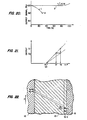
- the amount of the current I is dependent upon the oxygen partial pressure of the exhaust gas or, more particularly, as shown in Fig. 7, the starting current is changed as indicated by the solid line curves I 1 , 1 2 or I 3 in accordance with the oxygen partial pressure P el' Pe2 or P e3 , respectively.
- the threshhold current also varies or is different as indicated by I e1 , I e2 or I e3 , respectively. Similarily, the time when the threshhold current appears differs as indicated by the time periods T e1 , T e2 or T e3 , respectively.
- the oxygen partial pressure at the interface between the electrode and the diffusion resistor 16 during the oxygen withdrawal step is gradually reduced and, as shown in Fig. 8A then becomes zero at the time period T l .
- Measuring the electromotive force E between both the electrodes 12, 14 during that time period indicates that the electromotive force changes rapidly from OV to 1V at the time T 1 as shown most clearly in Fig. 8B. Therefore, it is possible to determine the time T 1 based on a change in the electromotive force E.
- the air-fuel ratio As a result of studying the relationship between the oxygen partial pressure of the exhaust gas, that is, the air-fuel ratio (A/F), and the time T 1 , it has been determined that a linear relationship exists between A/F and T from a rich mixture wherein A/F is less than the theoretical air-fuel ratio (A/F:14.7) to a lean mixture where A/F is greater than that value as shown most clearly in Fig. 9. Consequently, the air-fuel ratio can be measured by determining the time T.
- A/F the air-fuel ratio
- the exhaust gas contains carbon monoxide rather than oxygen and the partial pressure of the carbon monoxide increases linearly as the air-fuel ratio decreases; therefore, a rich air-fuel ratio can be measured by determining the partial pressure of the carbon monoxide.
- P e the partial pressure of the carbon monoxide in the exhaust gas
- the oxygen partial pressure at the interface between the electrode 12 and the diffusion resistor 16 reaches a balance state where it is assumed to be P e (CO) + P c (O 2 ), as shown most clearly in Fig. 2.
- P (CO) is 2% and Pe(02) is 3%
- the oxygen partial pressure at the interface becomes 2% since the oxygen reacts with the carbon monoxide in accordance with the following relationship:
- the oxygen partial pressure in the diffusion resistor 16 varies in the manner indicated by the solid lines T 0 , T 1 and T 2 in Fig. 10. Consequently, the period of time during which the oxygen partial pressure at the interface is zero represents the partial pressure of the carbon monoxide and, therefore, the air-fuel ratio.
- a change in the partial pressure of carbon monoxide per unit of air-fuel ratio in a rich mixture is twice that in the oxygen partial pressure per unit of the air-fuel ratio in a lean mixture so that there also exists a linear relationship between the time T and the air-fuel ratio A/F as shown most clearly in Fig. 9.
- a control measurement circuit 10 is provided.
- the air-fuel ratio detector or sensor includes a solid electrolyte 10 and a diffusion resistor 16 having a construction similar to Fig. 1, with the detector being installed in a gas passage 54 connected to a downstream side of a combustor 56 for an internal combustion engine, or the like.
- the terminals 34, 44 of the sensor section are connected to the control measurement circuit 100, with a main portion of the circuit 100 including a microprocessor 102 for controlling the device in accordance with a program stored therein which program may, for example, correspond to the flow diagram illustrated in Fig. 12 of the drawings.
- the microprocessor 102 executes a program in synchronism with signals from a clock 104 and is adapted to change over a relay 108 to close an upper switch thereof or to close a lower switch thereof with a signal issued to a terminal 106 of the microprocessor 102.
- a certain current I is passed between the electrodes on both sides of the electrolyte 10 to feed oxygen.
- a transistor 110 is operated at a voltage V 4 at terminal 112 of the microprocessor 102.
- the transistor 110 is conductive, the current is supplied from a power source 114 to produce a voltage V 2 through a detection resistor 116, which voltage is applied to the processor 102 from a terminal 118.
- a transistor 120 When the upper switch of the relay 108 is closed, it is possible to apply a voltage to withdraw oxygen, and a transistor 120 is operated with a voltage V 3 at a terminal 122 of the processor 102.
- the transistor 120 conducts, the voltage is applied from a power source 124, and a current I passing during the oxygen withdrawal step is detected through a detection resistor 126 and taken into the processor in the form of a voltage V 1 from a terminal 128, with the voltage V 1 also being used for detecting electromotive force between the electrodes.
- the combustor 56 is provided with a fuel adjusting valve 58 which is adapted to be opened and closed under the control of the microprocessor 102.
- Fig. 13 provides a flow diagram of a program built into the microprocessor 102. More particularly, in step S 40 , a basic fuel injection amount T p is determined in dependence upon both the intake air amount Q detected by an air flow sensor (not shown) and a rotational speed n detected by a crank angle sensor (not shown). In step S 42 , the particular air excess rate ⁇ 0 determined from the operating conditions such as, for example, rotational speed n, amount of intake air Q a and intake air temperature is read out of a map of air excess rates ⁇ 0 (air-fuel ratios) (A/F) 0 ) which are prestored in a RAM of the microprocessor 102.
- a map of air excess rates ⁇ 0 air-fuel ratios
- step S 44 the actual air excess rate (air-fuel ratio) (A/F) is then determined based on the time t temporarily stored in the step S 30 .
- step S 46 the measured air excess rate (air-fuel ratio) (A/F) is compared with a target air excess rate ⁇ 0 (air-fuel ratio (A/F) 0 ) to determine a deviation ⁇ .
- the air fuel injection amount T p is corrected in step S 48 using the deviation Ae and, in the step S 48 , represents a proportional constant.
- Figs. 14-16 represent another embodiment of the present invention wherein a current passing, during the step of withdrawing oxygen, after feeding oxygen into the diffusion resistor 16 to bring the oxygen partial pressure at the interface between the diffusion resistor 16 and the electrode into a balanced state where it is higher than the oxygen partial pressure of the exhaust gas by a predetermined or given value, is varied in the manner shown in Figs. 7 or 14.
- a current passing during the step of withdrawing oxygen, after feeding oxygen into the diffusion resistor 16 to bring the oxygen partial pressure at the interface between the diffusion resistor 16 and the electrode into a balanced state where it is higher than the oxygen partial pressure of the exhaust gas by a predetermined or given value, is varied in the manner shown in Figs. 7 or 14.
- the expression average value I means an integrated value of the current I in a range of a time period T 0 to T 1 which is indicated in the hatched area in Fig. 14, or, in the alternative, the actual average value thereof in a range from t 0 to t l .
- step S 58 if the time t is less than a predetermined time t 1 of, for example, 5ms, the steps S52-S56 are repeated and, if the time t is greater than 5ms, the integrated value of the current I until that time is stored as an average value I in step S 60 .
- the average value I is used in calculating the actual air excess rate illustrated in step S 44 in Fig. 13.
- Fig. 17 provides an example of yet another embodiment of the present invention wherein, in the illustrated embodiment, the variation rate of current during the oxygen withdrawing step is taken into account. More particularly, the current I during oxygen withdrawing is varied as shown in Fig. 17 and, as a result of a measuring of a time differential value dI/dt of the current I, that is, a variation rate of the current, just after starting to withdraw the oxygen with respect to the air-fuel ratios A/F, it has been determined that a linear relationship exists therebetween as shown most clearly in Fig. 18.
- step S 74 the current I(t0) which passes at the time T 0 of starting to withdraw oxygen as measured and it is then monitored in step S 76 until the time t exceeds a predetermined time (t l such as, for example, lms. After the lapse of the predetermined time (t 1 , the current I passing at that time t 1 is measured in step S 78 .
- dI/dt is calculated in step S 80 , with the calculation being based on the following relationship:
- the resultant value of dI/d t from the above relationship is then stored in S 82 and, subsequently, oxygen is continuously withdrawn until the time t exceeds a predetermined time t 2 such as, for example, 5ms. After a lapse of a time period t 2 , the microporcessor 102 returns to the first step S 70 .
- the oxygen withdrawing time is T j at a maximum and, in the case of measuring the time T in Fig. 9, the maximum time T. is measured.
- the oxygen content of the exhaust gas is about 6% in this situation.
- P e is 6% and, when the oxygen is withdrawn under these circumstances with P c being equal to 3%, the required time is about 6ms.
- P c is dependent upon the value of P c , that is, the diffusion resistance k determined by the porsity and the thickness of the resistor 16, the feeding current I, and the withdrawing current I. In other words, the time T.
- the measured result may be affected by dust adhering to the solid electrolyte 16.
- the measurement of the average current I can be made for about the half time, that is, for example, about 5ms.
- the measurement of dI/dt can be made for a much shorter period of time, but it is preferable to withdraw oxygen for about 5ms also in this situation, and this results from taking into account a reduction of the oxygen partial pressure of the exhaust gas.
- a period of about 10ms is enough to respectively feed and withdraw oxygen and the total period of 20ms is sufficiently short to enable a controlling of an internal combustion engine.
- the present. invention is less susceptible to the effects of dust and also, while the value of the threshold current is several mA at maximum, the initial current in the step of withdrawing oxygen reaches several times 10mA in accordance with the present invention thereby resulting in an increasing in the accuracy when measuring of the values of the current I and dI/dt.
- Fig. 20 provides an example of time dependent variations of an output signal from an air-fuel ratio detector and, more particularly, according to this figure, an output signal A is obtained with a conventional detector such as, for example, a detector disclosed in United States Patent 4,282,080, with an output signal B being obtained from a detector constructed in accordance with the present invention.
- a conventional detector such as, for example, a detector disclosed in United States Patent 4,282,080
- an output signal B being obtained from a detector constructed in accordance with the present invention.
- the previously proposed detector arrangement is arranged just to withdraw oxygen in the exhaust gas with a solid electrolyte, with the oxygen diffusing through the diffusion resistor, and with the oxygen content of the exhaust gas being measured based on the threshold current which flows during an oxygen withdrawal.
- the value of the threshold current varies in dependence upon the resistance value of the diffusion resistor and, if dust in the exhaust gas adheres to the surface of the diffusion resistor in contact with the exhaust gas, the resistance of such a dust adhering area would be increased.
- the resistance value within the diffusion resistor would remain unchanged and would be less than the dust adhering portion. Consequently, the limit current value is determined by the resistance value of the dust adhering portion and, for example, if dust adheres to the surface of the diffusion resistor and its resistance value is doulbed, the limit current value would be reduced by one-half.
- the output signal is gradually reduced with the lapse of time in the conventional detector, a problem arises in a misfiring of an engine when the detector is employed as a control arrangement for an internal combustion engine. More particularly, assuming that a conventional detector has an output characteristic such as shown by the solid line in Fig. 21, and further assuming that the characteristic is changed to be gradually reduced with a lapse of time as indicated by the broken line in Fig. 21, when the control unit is arranged to maintain the air-fuel ratio at, for example, 18, the output of the detector is reduced to the level 0 2 from the original level 0 1 and, in this case, the control unit determines that the air-fuel ratio at that time is 17 thereby reducing the supply of the amount of fuel so that the air fuel ratio is held at 18. Consequently, the mixture becomes too lean to ignite and the internal combustion engine stops.
- Fig. 22 provides a graphical illustration of the influence of the effects of adhering dust with respect to a lapse of a predetermined time period.
- the solid line corresponds to a situation wherein the oxygen partial pressure reaches a balance state at a time t i in Fig.
- the dotted line represent a balanced state of the oxygen partial pressure when the time dependent changes are included.
- the portion of the diffusion resistor 16-1 has an unchanged resistance value; whereas,.the portion of the diffusion resistor 16-2 has an increased resistance value due to the adhering dust.
- the angle 8 2 is twice the angle ⁇ 1 as apparent from Fig. 22.
- the given amount P c in a balanced state is expressed by k . I o when, without adhering dust where, k is the resistance value and I is the current value.
- the amount P c' in a balanced state is expressed by the following relationship:
- the portion undergoing changes in resistance due to the adhering dust has a thickness of 1 ⁇ m to 5 ⁇ m.
- the portion x is equal to 0.01 so that P c' is increased by about 1% relative to P.
- P c' is increased by only 5% relative to the P c .
- the output signal increases with the time-dependent changes thereby ensuring a prevention of a problem of misfiring when the detector is applied to an internal combustion engine.
- the above described time dependent changes can be calibrated in the following manner. More particularly, the fuel adjusting valve 58 of the combustor 56 in Fig. 11 is temporarily interrupted in its operation so that the gas passage 54 only contains air therein. At that time, the oxygen partial pressure is constant at, for example, 21%, so that an output signal I c in such a situation is measured and the resultant value is utilized to calibrate the time-dependent changes.
- the output signal I is expressed by the following equation, where k is a variable:
- the value of k can be determined by measuring I.
- the calibration of the time-dependent changes may be performed in accordance with the flow diagram shown in Fig. 23.
- the microprocessor 102 interrupts the fuel adjusting valve 58 in the step S 90 and waits for a lapse of a predetermined time period so that a space around the electrolyte 10 is filled with air.
- the signal I is measured in step S 94 , and measurement of the signal I is carried out in accordance with the flow diagram illustrated in Fig-. 16.
- the resultant I is assumed to be I c and, in step Sg 6 , the changed diffusion resistance k is calculated using the foregoing equation.
- time-dependent changes can be calibrated in a similar manner using the signal t or dI/dt, in addition to the signal I.
- the effect of the time-dependent change is slight even without including the protective layer 18; however, the overall advantageous effects can be further reduced by utilizing the protective layer 18 to trap dust and, consequently, it is preferable to provide a protective layer 18.
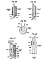
- the sensor section employed in the present invention is not limited to the sensor construction illustrated in Fig. 1 and, for example, the sensor section may take other possible constructions such as, for example, the constructions illustrated in Figs. 24-26 wherein the sensor sections are arranged so that both the electrodes are exposed to the exhaust gas instead of exposing either one of them to the atmosphere.
- the embodiments illustrated in Figs. 27 and 28 are arranged so that a single-holed diffusion resistor is employed in place of the porous diffusion resistor.
- a platinum paste is applied onto both sides of a zirconia substrate 200 (Zr0 2 : 92% by weight, Y 2 0 3 : 8%'by weight) with a thickness of 400um, and then baked to form electrodes 202, 204.
- a diffusion resistor 206 is coated on the electrode 202, with the diffusion resistor 206 being formed of MgO-A1203 spinel and has a thickness of about 200pm.
- a pore volume is about O.lcc/g.
- the diffusion resistor 206 is, in turn, coated with a protective layer 208 and, the electrode 204 is also coated with a protective layer 210 with a pore volume of each of the protective layers 208, 210 being larger than 0.2cc/g.
- the porosity of the electrode 204 is also comparable to that of the protective layers 208, 210.
- Fig. 24 is operated through the steps of first feeding oxygen from the electrode 204 to the side of the electrode 202 and then withdrawing the oxygen from the side of the electrode 202 to the side of the electrode 204. Consequently, such a sensor is entirely exposed to the exhaust gas without employing any reference oxygen source such as the atmosphere; however the exhaust gas contains oxygen in a small amount of oxygen exists even in a region less than the theoretical air/fuel ratio, so that oxygen can be employed as an oxygen source.
- oxygen resides in the electrode 204 and the protective layer 210.
- an electrode 218 is formed on an alumina substrate 212 with a thickness of lmm with platinum paste.
- An electrolyte 216 of a thickness of 100pm - 300 ⁇ m is formed on the electrode 218 with a plasma jet.
- the electrolyte consists essentially of zr0 2 in the range of 90-94% by weight and Yb 2 0 3 of about 6-10% by weight.
- An electrode 214 is provided on the electrolyte 216, with the electrode 214 being formed of a platinum paste, which is coated with a protective layer 220 on the outer side thereof.
- the electrolyte 216 is porous and also serves as a diffusion resistor.
- a heater 222 is built into the alumina substrate 222.
- the sensor arrangement of Fig. 25 is operated in the same manner as that of Fig. 24.
- a pair of platinum electrodes 226, 228 each having a diameter of 0.4mm are built in parellel with a spacing of two millmeters therebetween into a pellet-like porous electrolyte 224 which is about 3mm in diameter and about 1.9mm in thickness.
- the electrolyte 224 is formed of ZrO 2 stabilized with Y 2 0 3 and has a porosity of 22%.
- oxygen is first fed from the electrode 228 toward the electrode 226 so that the oxygen content around the electrode 226 comes into a balanced state where it is higher than the oxygen content of the exhaust gas and then the direction of current is reversed to withdraw the oxygen.
- a coating 230 of gold is provided on the outer peripheral surface of the electrode 228 to prevent the reaction of oxygen with carbon monoxide thereby making it possible to avoid a reduction in the oxygen content near the electrode 228 even in a lean mixture where the air-fuel ratio is less than the theoretically idea ratio. Stated in a different manner, even in a lean mixture where the air-fuel ratio is less than the theoretical ideal, a sufficient amount of oxygen can be supplied to the space around the electrode 226.
- Fig. 27 seven laminated green sheets 232-244 are provided, with each of the sheets being formed of ZrO 2 stabilized with Y 2 0 3 the green sheet 234 is provided with a groove 246 which serves as a communication hole with the atmosphere.
- the groove 246 can be formed in such a manner that an organic binder is packed into the portion which will latter become the groove and then burnt out at the time of a sintering of the green sheet 234.
- Electrodes 248, 250 are each provided on either side of the green sheet 236 by printing, with the green sheet 238 functioning to provide a first chamber 252.
- the green sheet 240 is provided with a first orifice 254.which serves as a diffusion resistor, and the green sheet 242 functions to provide a second chamber 256.
- the green sheet 244 is provided with a second orifice 258 which serves as a diffusion resistor.
- the first chamber 252 has a volume of 3mm 3
- the second chamber 256 having a volume of 6mm 3 .
- Each of the orifices 254, 258 have a diameter of 0.3mm and the green sheets each have a thickness of 100 ⁇ m-400 ⁇ m.
- oxygen is supplied to both chambers 252 and 256 so that the oxygen partial pressure in the chamber 256 reaches a balanced state where it is higher than the oxygen partial pressure P of the exhaust gas by a value of k 1 .I 0 , and the oxygen partial pressure in the chamber 252 comes into a balanced state where it is higher than the oxygen partial pressure in the chamber 256 by a value of k 2 .I 0 , with k 1 , k 2 respectively representing diffusion resistances of the orifices 258, 254.
- the oxygen partial pressure of the exhaust gas is then measured by withdrawing oxygen from the chamber 252.
- the embodiment of Fig. 28 is formed by three laminated green sheets 260-264, with each of the green sheets 260-264 being formed of ZrO 2 stabilized with Y 2 0 3 .
- a groove.266 is formed in a manner similar to the groove 246 in the construction of Fig. 27, and electrodes 268, 270 are respectively provided on either side of the green sheet 260.
- the electrode 270 is coated with a protective layer 272.
- the groove 266 has a height h of 200pm, a width of lmm, and a length of 20mm, with one end 274 of the groove 266 being opened to the exhaust gas, and with the groove 266 itself functioning as a diffusion resistor.
- the control-measurement circuitry 100 may be arranged so that, with a terminal e 1 undergoing no input, a positive feedback signal is supplied to a non-inverted input terminal of an operational amplifier OP from an output terminal thereof in accordance with a ratio of resistance R 2 to resistance R 3 , and the output voltage e i of the amplifier is held at a positive potential while being clipped with the diodes D 1 , D 2 .
- a pulse signal is applied to the terminal e 1 in such an equilibrium state, the output voltage e i is inverted in its polarity to a negative potential.
- a square wave, a pulse or sine wave can be applied as a signal to the input terminal e 1 and, when a pulse is applied to the input terminal e 1 with the voltage e i being in a negative state, the output voltage e i returns to the original positive state.
- the steps of feeding and withdrawing oxygen in the sensor section can be controlled with a trigger signal from a microprocessor 102.
- the current i during the step of withdrawing oxygen is measured through a detection resistor R 4 and then taken into the microprocessor 102 and, upon this occurring, the values of t, dI/dt, I, etc. are then determined.
- e s is proportional to the air excess rate (air-fuel ratio A/F).
- a circuit 302 serves as a circuit for generating positive and negative pulses employing transistors Q 1 , Q 2 and Q 3 . More particularly, positive and negative output pulses e l , e 2 are produced from a positive DC power source +V BB .
- the transistor Q 1 produces a positive pulse e, while the transistors Q 2 and Q 3 produce the negative pulse e 2 of an opposite phase.
- An output e 3 is produced when the negative pulse e 2 is applied to a delay circuit for delaying e 2 to an extent of time t.
- a combined output e i of both signals e 1 and e 3 is obtained by an adder 304.
- the period T 1 is utilized for feeding oxygen and the period T 2 is utilized for withdrawing oxygen.
- the applied voltage becomes zero and it is determined whether the current air-fuel ratio is leaner or richer than the theoretically ideal air-fuel ratio by measuring the electromotive force produced between both electrodes. If the air-fuel ratio is lean, a voltage e c is applied to a transistor Q 4 for blocking an input of the voltage e 3 to the adder 304. If the air-fuel ratio is rich, the voltage e 3 is allowed to enter the adder 304 for feeding oxygen thereby preventing the sensor section from coming into an electron conductive region.
Landscapes
- Chemical & Material Sciences (AREA)
- Health & Medical Sciences (AREA)
- Life Sciences & Earth Sciences (AREA)
- Engineering & Computer Science (AREA)
- Biochemistry (AREA)
- Immunology (AREA)
- Physics & Mathematics (AREA)
- Analytical Chemistry (AREA)
- Chemical Kinetics & Catalysis (AREA)
- General Health & Medical Sciences (AREA)
- General Physics & Mathematics (AREA)
- Electrochemistry (AREA)
- Pathology (AREA)
- Molecular Biology (AREA)
- Combustion & Propulsion (AREA)
- Mechanical Engineering (AREA)
- General Engineering & Computer Science (AREA)
- Measuring Oxygen Concentration In Cells (AREA)
- Investigating Or Analyzing Materials By The Use Of Electric Means (AREA)
Applications Claiming Priority (2)
| Application Number | Priority Date | Filing Date | Title |
|---|---|---|---|
| JP59027138A JPS60171447A (ja) | 1984-02-17 | 1984-02-17 | 空燃比検出方法 |
| JP27138/84 | 1984-02-17 |
Publications (3)
| Publication Number | Publication Date |
|---|---|
| EP0152940A2 true EP0152940A2 (fr) | 1985-08-28 |
| EP0152940A3 EP0152940A3 (en) | 1986-11-20 |
| EP0152940B1 EP0152940B1 (fr) | 1988-07-20 |
Family
ID=12212687
Family Applications (1)
| Application Number | Title | Priority Date | Filing Date |
|---|---|---|---|
| EP85101767A Expired EP0152940B1 (fr) | 1984-02-17 | 1985-02-18 | Appareil et méthode de détection de rapport air/carburant |
Country Status (5)
| Country | Link |
|---|---|
| US (1) | US4629535A (fr) |
| EP (1) | EP0152940B1 (fr) |
| JP (1) | JPS60171447A (fr) |
| KR (1) | KR890000080B1 (fr) |
| DE (1) | DE3563868D1 (fr) |
Cited By (3)
| Publication number | Priority date | Publication date | Assignee | Title |
|---|---|---|---|---|
| EP0193123A3 (en) * | 1985-02-28 | 1987-10-21 | Hitachi, Ltd. | Air-fuel ratio detection system |
| FR2603697A1 (fr) * | 1986-09-10 | 1988-03-11 | Hitachi Ltd | Capteur de detection du rapport air/carburant pour un moteur a combustion interne |
| FR2609550A1 (fr) * | 1987-01-09 | 1988-07-15 | Hitachi Ltd | Detecteur de la teneur en oxygene |
Families Citing this family (12)
| Publication number | Priority date | Publication date | Assignee | Title |
|---|---|---|---|---|
| ATE78341T1 (de) * | 1985-11-13 | 1992-08-15 | Esa Inc | Elektrochemisches pruefsystem. |
| US5074988A (en) * | 1986-02-20 | 1991-12-24 | Raychem Corporation | Apparatus for monitoring an electrolyte |
| JP3333678B2 (ja) * | 1996-01-05 | 2002-10-15 | 株式会社日立製作所 | ガス成分センサ及び触媒診断装置 |
| KR20020060714A (ko) * | 1999-10-15 | 2002-07-18 | 덴턴 마이클 | 가스센서구조및 이를 사용하는 방법 |
| US6565723B1 (en) * | 2000-12-04 | 2003-05-20 | Delphi Technologies, Inc. | Isolated ground sensor achieved using alumina coating over spinel coating |
| DE102005054144A1 (de) * | 2005-11-14 | 2007-05-16 | Bosch Gmbh Robert | Gassensor |
| DE102005056515A1 (de) * | 2005-11-28 | 2007-05-31 | Robert Bosch Gmbh | Verfahren zur Erkennung der Diffusionsgaszusammensetzung in einer Breitband-Lambdasonde |
| DE102006062056A1 (de) | 2006-12-29 | 2008-07-03 | Robert Bosch Gmbh | Sensorelement mit unterdrückter Fettgasreaktion |
| US9309796B2 (en) * | 2011-03-16 | 2016-04-12 | Toyota Jidosha Kabushiki Kaisha | Particulate matter processing apparatus |
| US9284869B2 (en) * | 2011-03-16 | 2016-03-15 | Toyota Jidosha Kabushiki Kaisha | Particulate matter processing apparatus |
| JP5333675B2 (ja) * | 2011-03-16 | 2013-11-06 | トヨタ自動車株式会社 | 粒子状物質処理装置 |
| JP6359373B2 (ja) * | 2013-09-05 | 2018-07-18 | 日本特殊陶業株式会社 | ガスセンサ素子及びガスセンサ |
Citations (5)
| Publication number | Priority date | Publication date | Assignee | Title |
|---|---|---|---|---|
| JPS5366292A (en) | 1976-11-24 | 1978-06-13 | Westinghouse Electric Corp | Combustible sensor |
| JPS55125548A (en) | 1979-03-16 | 1980-09-27 | Pioneer Electronic Corp | Rotary type encoder and its preparation |
| JPS55166039A (en) | 1979-06-12 | 1980-12-24 | Nissan Motor Co Ltd | Air fuel ratio detector |
| US4272331A (en) | 1980-03-03 | 1981-06-09 | Ford Motor Company | Oscillatory mode oxygen sensor and method |
| US4282080A (en) | 1979-03-10 | 1981-08-04 | Robert Bosch Gmbh | Electrochemical sensor, particularly for oxygen determination in combustion gases |
Family Cites Families (7)
| Publication number | Priority date | Publication date | Assignee | Title |
|---|---|---|---|---|
| JPS584986B2 (ja) * | 1978-06-16 | 1983-01-28 | 日産自動車株式会社 | 酸素濃度測定装置 |
| JPS5562349A (en) * | 1978-11-02 | 1980-05-10 | Nissan Motor Co Ltd | Measuring method for air fuel ratio |
| JPS55155859A (en) * | 1979-05-25 | 1980-12-04 | Towa Kogyo Kk | Method of waterproofing |
| JPS6029066B2 (ja) * | 1979-07-28 | 1985-07-08 | 日産自動車株式会社 | 空燃比制御信号発生装置 |
| NL7906833A (nl) * | 1979-09-13 | 1981-03-17 | Philips Nv | Gasanalyseapparaat. |
| JPS58105014A (ja) * | 1981-12-18 | 1983-06-22 | Nissan Motor Co Ltd | エンジンの空燃比測定装置 |
| US4418566A (en) * | 1982-01-25 | 1983-12-06 | Sun Electric Corporation | Gas analyzing techniques |
-
1984
- 1984-02-17 JP JP59027138A patent/JPS60171447A/ja active Granted
-
1985
- 1985-02-18 EP EP85101767A patent/EP0152940B1/fr not_active Expired
- 1985-02-18 KR KR1019850001008A patent/KR890000080B1/ko not_active Expired
- 1985-02-18 DE DE8585101767T patent/DE3563868D1/de not_active Expired
- 1985-02-19 US US06/702,750 patent/US4629535A/en not_active Expired - Lifetime
Patent Citations (7)
| Publication number | Priority date | Publication date | Assignee | Title |
|---|---|---|---|---|
| JPS5366292A (en) | 1976-11-24 | 1978-06-13 | Westinghouse Electric Corp | Combustible sensor |
| US4158166A (en) | 1976-11-24 | 1979-06-12 | Westinghouse Electric Corp. | Combustibles analyzer |
| US4282080A (en) | 1979-03-10 | 1981-08-04 | Robert Bosch Gmbh | Electrochemical sensor, particularly for oxygen determination in combustion gases |
| JPS55125548A (en) | 1979-03-16 | 1980-09-27 | Pioneer Electronic Corp | Rotary type encoder and its preparation |
| JPS55166039A (en) | 1979-06-12 | 1980-12-24 | Nissan Motor Co Ltd | Air fuel ratio detector |
| US4304652A (en) | 1979-06-12 | 1981-12-08 | Nissan Motor Company, Limited | Device for detection of air/fuel ratio from oxygen partial pressure in exhaust gas |
| US4272331A (en) | 1980-03-03 | 1981-06-09 | Ford Motor Company | Oscillatory mode oxygen sensor and method |
Cited By (6)
| Publication number | Priority date | Publication date | Assignee | Title |
|---|---|---|---|---|
| EP0193123A3 (en) * | 1985-02-28 | 1987-10-21 | Hitachi, Ltd. | Air-fuel ratio detection system |
| FR2603697A1 (fr) * | 1986-09-10 | 1988-03-11 | Hitachi Ltd | Capteur de detection du rapport air/carburant pour un moteur a combustion interne |
| GB2195772A (en) * | 1986-09-10 | 1988-04-13 | Hitachi Ltd | Decontaminating air-fuel ratio sensor |
| GB2195772B (en) * | 1986-09-10 | 1991-06-26 | Hitachi Ltd | Air-fuel ratio sensor |
| FR2609550A1 (fr) * | 1987-01-09 | 1988-07-15 | Hitachi Ltd | Detecteur de la teneur en oxygene |
| GB2200460A (en) * | 1987-01-09 | 1988-08-03 | Hitachi Ltd | Solid electrolyte oxygen concentration detector |
Also Published As
| Publication number | Publication date |
|---|---|
| US4629535A (en) | 1986-12-16 |
| DE3563868D1 (en) | 1988-08-25 |
| KR850006895A (ko) | 1985-10-21 |
| JPS60171447A (ja) | 1985-09-04 |
| JPH053547B2 (fr) | 1993-01-18 |
| EP0152940B1 (fr) | 1988-07-20 |
| KR890000080B1 (ko) | 1989-03-07 |
| EP0152940A3 (en) | 1986-11-20 |
Similar Documents
| Publication | Publication Date | Title |
|---|---|---|
| EP1074834B1 (fr) | Procédé et appareil de mesure de la concentration d'oxydes d'azote | |
| EP0152940A2 (fr) | Appareil et méthode de détection de rapport air/carburant | |
| EP0903576B1 (fr) | Capteur de gaz | |
| US6383354B1 (en) | Gas concentration sensing apparatus | |
| JP2000065793A (ja) | ガス混合気の酸素濃度を測定する測定センサの制御のための方法 | |
| EP0144057A2 (fr) | Appareil pour mesurer la concentration d'oxygène et méthode de fabrication de l'appareil | |
| EP0709668B1 (fr) | Procédé et appareil de mesure de la concentration des composants d'un gaz | |
| US4499880A (en) | Air-fuel ratio controlling apparatus for internal combustion engine | |
| CN110646489B (zh) | 气体传感器 | |
| US4723521A (en) | Air/fuel ratio control system for an internal combustion engine | |
| JP2024082357A (ja) | ガスセンサ及びガスセンサの制御方法 | |
| JPH0413961A (ja) | 空燃比検出装置 | |
| JPH0245819B2 (fr) | ||
| US20240011938A1 (en) | Sensor element and gas sensor | |
| JPH0428899B2 (fr) | ||
| JP2879281B2 (ja) | 酸素センサの制御装置 | |
| US20240011937A1 (en) | Sensor element and gas sensor | |
| JPH01152358A (ja) | 酸素センサ | |
| JPH0415386B2 (fr) | ||
| US20240011942A1 (en) | Sensor element and gas sensor | |
| JPS60224051A (ja) | 空燃比検出装置 | |
| JPH0436341B2 (fr) | ||
| JP3048256B2 (ja) | 空燃比検出方法 | |
| JPS60144656A (ja) | 空燃比制御装置 | |
| JP2023144582A (ja) | ガスセンサ |
Legal Events
| Date | Code | Title | Description |
|---|---|---|---|
| PUAI | Public reference made under article 153(3) epc to a published international application that has entered the european phase |
Free format text: ORIGINAL CODE: 0009012 |
|
| AK | Designated contracting states |
Designated state(s): AT BE CH DE FR GB IT LI LU NL SE |
|
| RBV | Designated contracting states (corrected) |
Designated state(s): CH DE FR GB IT LI NL SE |
|
| PUAL | Search report despatched |
Free format text: ORIGINAL CODE: 0009013 |
|
| AK | Designated contracting states |
Kind code of ref document: A3 Designated state(s): CH DE FR GB IT LI NL SE |
|
| 17P | Request for examination filed |
Effective date: 19861121 |
|
| 17Q | First examination report despatched |
Effective date: 19870416 |
|
| GRAA | (expected) grant |
Free format text: ORIGINAL CODE: 0009210 |
|
| AK | Designated contracting states |
Kind code of ref document: B1 Designated state(s): CH DE FR GB IT LI NL SE |
|
| REF | Corresponds to: |
Ref document number: 3563868 Country of ref document: DE Date of ref document: 19880825 |
|
| ET | Fr: translation filed | ||
| ITF | It: translation for a ep patent filed | ||
| PGFP | Annual fee paid to national office [announced via postgrant information from national office to epo] |
Ref country code: SE Payment date: 19890221 Year of fee payment: 5 |
|
| ITTA | It: last paid annual fee | ||
| PGFP | Annual fee paid to national office [announced via postgrant information from national office to epo] |
Ref country code: NL Payment date: 19890228 Year of fee payment: 5 |
|
| PGFP | Annual fee paid to national office [announced via postgrant information from national office to epo] |
Ref country code: CH Payment date: 19890428 Year of fee payment: 5 |
|
| PLBE | No opposition filed within time limit |
Free format text: ORIGINAL CODE: 0009261 |
|
| STAA | Information on the status of an ep patent application or granted ep patent |
Free format text: STATUS: NO OPPOSITION FILED WITHIN TIME LIMIT |
|
| 26N | No opposition filed | ||
| PG25 | Lapsed in a contracting state [announced via postgrant information from national office to epo] |
Ref country code: SE Effective date: 19900219 |
|
| PG25 | Lapsed in a contracting state [announced via postgrant information from national office to epo] |
Ref country code: LI Effective date: 19900228 Ref country code: CH Effective date: 19900228 |
|
| PG25 | Lapsed in a contracting state [announced via postgrant information from national office to epo] |
Ref country code: NL Effective date: 19900901 |
|
| NLV4 | Nl: lapsed or anulled due to non-payment of the annual fee | ||
| REG | Reference to a national code |
Ref country code: CH Ref legal event code: PL |
|
| EUG | Se: european patent has lapsed |
Ref document number: 85101767.3 Effective date: 19901107 |
|
| PGFP | Annual fee paid to national office [announced via postgrant information from national office to epo] |
Ref country code: FR Payment date: 20010123 Year of fee payment: 17 |
|
| PGFP | Annual fee paid to national office [announced via postgrant information from national office to epo] |
Ref country code: GB Payment date: 20010125 Year of fee payment: 17 |
|
| PGFP | Annual fee paid to national office [announced via postgrant information from national office to epo] |
Ref country code: DE Payment date: 20010330 Year of fee payment: 17 |
|
| REG | Reference to a national code |
Ref country code: GB Ref legal event code: IF02 |
|
| PG25 | Lapsed in a contracting state [announced via postgrant information from national office to epo] |
Ref country code: GB Free format text: LAPSE BECAUSE OF NON-PAYMENT OF DUE FEES Effective date: 20020218 |
|
| PG25 | Lapsed in a contracting state [announced via postgrant information from national office to epo] |
Ref country code: DE Free format text: LAPSE BECAUSE OF NON-PAYMENT OF DUE FEES Effective date: 20020903 |
|
| GBPC | Gb: european patent ceased through non-payment of renewal fee |
Effective date: 20020218 |
|
| PG25 | Lapsed in a contracting state [announced via postgrant information from national office to epo] |
Ref country code: FR Free format text: LAPSE BECAUSE OF NON-PAYMENT OF DUE FEES Effective date: 20021031 |
|
| REG | Reference to a national code |
Ref country code: FR Ref legal event code: ST |