EP0152971B1 - Temperatursteuerung und Anzeigeeinrichtung - Google Patents
Temperatursteuerung und Anzeigeeinrichtung Download PDFInfo
- Publication number
- EP0152971B1 EP0152971B1 EP85200034A EP85200034A EP0152971B1 EP 0152971 B1 EP0152971 B1 EP 0152971B1 EP 85200034 A EP85200034 A EP 85200034A EP 85200034 A EP85200034 A EP 85200034A EP 0152971 B1 EP0152971 B1 EP 0152971B1
- Authority
- EP
- European Patent Office
- Prior art keywords
- arrangement
- counter
- thermostat
- count
- temperature
- Prior art date
- Legal status (The legal status is an assumption and is not a legal conclusion. Google has not performed a legal analysis and makes no representation as to the accuracy of the status listed.)
- Expired
Links
- 230000000007 visual effect Effects 0.000 claims description 9
- 101000666730 Homo sapiens T-complex protein 1 subunit alpha Proteins 0.000 claims description 3
- 102100038410 T-complex protein 1 subunit alpha Human genes 0.000 claims description 3
- 238000005485 electric heating Methods 0.000 claims description 3
- 101100384866 Saccharomyces cerevisiae (strain ATCC 204508 / S288c) COT1 gene Proteins 0.000 claims description 2
- 230000001419 dependent effect Effects 0.000 claims 2
- XEEYBQQBJWHFJM-UHFFFAOYSA-N Iron Chemical compound [Fe] XEEYBQQBJWHFJM-UHFFFAOYSA-N 0.000 description 20
- 239000003990 capacitor Substances 0.000 description 17
- 238000009499 grossing Methods 0.000 description 10
- 229910052742 iron Inorganic materials 0.000 description 10
- 230000007935 neutral effect Effects 0.000 description 9
- 238000010438 heat treatment Methods 0.000 description 8
- 230000001351 cycling effect Effects 0.000 description 7
- XLYOFNOQVPJJNP-UHFFFAOYSA-N water Substances O XLYOFNOQVPJJNP-UHFFFAOYSA-N 0.000 description 6
- 238000010792 warming Methods 0.000 description 4
- 238000010411 cooking Methods 0.000 description 2
- 235000000396 iron Nutrition 0.000 description 2
- 238000010409 ironing Methods 0.000 description 2
- 229910052754 neon Inorganic materials 0.000 description 2
- GKAOGPIIYCISHV-UHFFFAOYSA-N neon atom Chemical compound [Ne] GKAOGPIIYCISHV-UHFFFAOYSA-N 0.000 description 2
- 230000003252 repetitive effect Effects 0.000 description 2
- 238000010079 rubber tapping Methods 0.000 description 2
- 238000005406 washing Methods 0.000 description 2
- 241000532348 Gallirallus modestus Species 0.000 description 1
- 235000008429 bread Nutrition 0.000 description 1
- 238000001816 cooling Methods 0.000 description 1
- 238000010586 diagram Methods 0.000 description 1
- 239000000428 dust Substances 0.000 description 1
- 238000000034 method Methods 0.000 description 1
- 238000012986 modification Methods 0.000 description 1
- 230000004048 modification Effects 0.000 description 1
- 230000001105 regulatory effect Effects 0.000 description 1
- 230000000284 resting effect Effects 0.000 description 1
- 230000002441 reversible effect Effects 0.000 description 1
- 230000000630 rising effect Effects 0.000 description 1
- 238000012163 sequencing technique Methods 0.000 description 1
Images


Classifications
-
- D—TEXTILES; PAPER
- D06—TREATMENT OF TEXTILES OR THE LIKE; LAUNDERING; FLEXIBLE MATERIALS NOT OTHERWISE PROVIDED FOR
- D06F—LAUNDERING, DRYING, IRONING, PRESSING OR FOLDING TEXTILE ARTICLES
- D06F75/00—Hand irons
- D06F75/08—Hand irons internally heated by electricity
- D06F75/26—Temperature control or indicating arrangements
-
- D—TEXTILES; PAPER
- D06—TREATMENT OF TEXTILES OR THE LIKE; LAUNDERING; FLEXIBLE MATERIALS NOT OTHERWISE PROVIDED FOR
- D06F—LAUNDERING, DRYING, IRONING, PRESSING OR FOLDING TEXTILE ARTICLES
- D06F39/00—Details of washing machines not specific to a single type of machines covered by groups D06F9/00 - D06F27/00
- D06F39/04—Heating arrangements
-
- G—PHYSICS
- G05—CONTROLLING; REGULATING
- G05D—SYSTEMS FOR CONTROLLING OR REGULATING NON-ELECTRIC VARIABLES
- G05D23/00—Control of temperature
- G05D23/19—Control of temperature characterised by the use of electric means
- G05D23/1906—Control of temperature characterised by the use of electric means using an analogue comparing device
- G05D23/1909—Control of temperature characterised by the use of electric means using an analogue comparing device whose output amplitude can only take two discrete values
-
- G—PHYSICS
- G05—CONTROLLING; REGULATING
- G05D—SYSTEMS FOR CONTROLLING OR REGULATING NON-ELECTRIC VARIABLES
- G05D23/00—Control of temperature
- G05D23/19—Control of temperature characterised by the use of electric means
- G05D23/275—Control of temperature characterised by the use of electric means with sensing element expanding, contracting, or fusing in response to changes of temperature
Definitions
- This invention relates to a temperature control and indicating arrangement including an electric heating element, a thermostat in series with said element and responsive to the heat generated thereby, and indicator means which responds to operation of the thermostat to indicate when the temperature in the region of the thermostat reaches a value determined by the thermostat.
- Such arrangements are well known and are used, for example, on domestic electrical equipment such as variable-temperature cooking pots, deep fat fryers, toasters, and smoothing irons.
- the indicator means is typically a neon lamp connected across the thermostat contacts such that the lamp lights when the contacts are open, i.e. the lamp gives a positive visible indication that the temperature in the region of the thermostat has reached the required value.
- the heating element is disconnected by the thermostat and this subsequently results in the thermostat contacts re-closing.
- the lamp is therefore short-circuited and goes out during the re-heating period. The cycle is then repetitive until such time as the thermostat setting is changed or the apparatus is switched off.
- the lamp is not alight and there is no positive indication that the apparatus is in fact at its working temperature.
- the apparatus is in its initial warming-up period and is not yet at its working temperature, is at the required temperature, is not switched on, or has a faulty heating element.
- the object of the present invention is at least to mitigate this problem.
- the invention provides a temperature control and indicating arrangement including an electric heating element, a thermostat connected in series with said element and responsive to the heat generated thereby, and indicator means which responds to operation of the thermostat to indicate when the temperature in the region of the thermostat reaches a value determined by the thermostat, characterised in that the arrangement further includes
- the counter of such an arrangement is used to check that there have been at least two operations of the thermostat and, therefore, that the thermostat is actually cycling at the required temperature, and also to maintain an uninterrupted visual display until the thermostat setting is changed or the apparatus is switched off.
- the use of a counter makes further advantages possible. Either or both of the reset and first count positions (0 and 1 respectively) can be used to cause a "waiting" indicator to be illuminated. In this manner it can be arranged that a positive indication is given the whole time the arrangement is in use, so that the user will know either that the arrangement is in the process of warming up to the required temperature or that it is satisfactorily maintaining the required temperature.
- temperatures may have respective count positions allocated thereto, and these positions may have respective indicators associated therewith.
- these temperatures may be those set out in the international standard "iron" symbol, namely 210°C (HOT), 160°C (WARM) and 120°C (COOL). These are represented by three dots, two dots and one dot, respectively, arranged in the symbol representing a smoothing iron.
- the indicators could be used either on the basis-of an individual indicator for each of the three temperatures or on ths basis of one for each dot. In the former case, only one of the three indicators would be illumiated at any one time whereas in the second case either one, two, or all three indicators would be illuminated.
- a principal advantage arising from the use of a counter is that counters are manufactured in vast quantities and, hence, can be very cheap indeed.
- This means that an arrangement according to the invention can be added to a relatively low cost apparatus such as a smoothing iron, water heater, or fat fryer with only a small increase in the selling price.
- a d.c. supply for the electronic components is derived from the mains voltage supply by a rectifying circuit comprising a dropping resistor R1 in series with a diode D1, and a smoothing/ regulating circuit comprising a reservoir capacitor C1 and a voltage-regulating zener diode Z which, for example, maintains the voltage on the d.c. rail DC at +15V with respect to the terminal (N (i.e. the neutral rail).
- thermostat TH The opening and closing of the contacts of thermostat TH is detected by a voltage divider R2, R3 connected across the thermostat, the tapping point T of the divider being connected to a rectifying and smoothing circuit comprising diode D2 and capacitor C2.
- the junction of diode D2 and capacitor C2 is connected via a current-limiting resistor R4 to the base of an input transistor T1 of a conventional Schmitt trigger circuit S comprising transistors T1, T2 and resistors R5 to R9.
- the output OP of trigger circuit S is connected to a non-inverting input of an AND-gate A the output of which is connected to the clock input CK of a counter CT.
- Counter CT has a series of counter outputs 0 0 , 0 1 , O z , and a master reset input MR.
- a "high” signal e.g. +15V with respect to the neutral rail N
- the first subsequent "high” signal pulse on input CK causes the counter to step once and provide a "high” signal on output 0 1
- the signal on output 0 0 simultaneously goes “low”-i.e. to the neutral rail potential.
- the next pulse at input CK steps the counter to give a "high” signal on output O z .
- Output 0 0 is connected via an isolating diode D3 to a light emitting diode (LED) L1 in series with a current-limiting resistor R10.
- Output 0 1 is connected to the junction point of diode D3 and LED L1 via a further isolating diode D4.
- Output O2 is connected to a second LED L2 in series with current-limiting resistor R11 and is also connected to the inverting input of gate A.
- a reset circuit RS includes a switch bank SB with a rotatable switch arm SA attached to an adjusting spindle SP of the thermostat TH. Rotation of spindle SP sets the thermostat TH to any required temperature in the range which is selectable in this manner.
- the contacts of switch bank SB are connected in common to the rail DC and are assumed to be sufficiently close that a relatively small rotary adjustment of spindle SP will cause switch arm SP to move from one contact, or from the space between two adjacent contacts, to the next contact.
- Switch arm SA is connected to the neutral rail via a resistor R14 and to the reset input MR via a capacitor C3 and a diode D5.
- the junction of capacitor C3 and diode D5 is connected to the neutral rail via a resistor R13.
- the positive rail DC is connected to the reset input MR via a capacitor C4 and a diode D6, the junction of C4 and D6 being connected to the neutral rail via a resistor R12.
- heater element HE is energised via the closed contacts of the thermostat TH which senses the temperature of whatever medium is being heated by the heater.
- the heating element HE therefore starts to heat the apparatus concerned which may, for example, be an electric smoothing iron, a sandwich or bread toaster, a water heater, a coffee maker, or a fat fryer.
- counter CT was reset to zero (a "high” on output 0 0 ) when the mains supply was first applied, and therefore the "low” output signal on output O2 enables the gate A via its inverting input.
- the "high” signal at point OF causes the counter CT to step once to give a "high” signal on output 0 1 and a “low” signal on output O o .
- LED L1 continues to give a positive signal because it is now provided with its illuminating voltage from output 0 1 instead of O o .
- the temperature in the region of the thermostat continues to rise for a while due to the thermal capacity of the body being heated.
- the body being heated namely the sole plate-is required to have a relatively high thermal capacity and there is a delay between the instant B at which the heating element is switched off and the instant C at which the temperature in the region of the thermostat begins to fall.
- the temperature then falls, at a relatively slower rate due to the thermal capacity, until at instant D the thermostat contacts close again to restart the heating cycle.
- the voltage at point T drops to zero and the Schmitt trigger S resets and removes the "high" signal at the input to gate A.
- the "high" signal on output 0 2 via the inverting input of gate A, inhibits the gate and prevents any further stepping of the counter prior to the next reset pulse on input MR.
- the thermostat contacts continue to cycle, a steady indication that the arrangement is at the required working temperature is given to the user.
- the first reclosure at instant D is the one most prone to faulty operation-once the thermostat has satisfactorily completed its first operating cycle, faulty operation in any succeeding cycle is extremely rare. Thus in the event of a faulty contact, LED L2 will not light until the fault is cleared or clears itself.
- the indication by LED L1 that the arrangement is "on" and is warming up may not be needed.
- LED L2 is illuminated-and remains illuminated-only when and so long as the arrangement is at the working temperature.
- the ambiguity of the known system i.e. that if the lamp is not illuminated then the user does not know whether the arrangement is warming up or is usable-does not exist.
- the indicator lamp is connected across the heater element and so its operation is the reverse of the known system hitherto referred to. It will be appreciated that this indicator lamp operation also gives rise to an ambiguous indication, namely that if the lamp is illuminated, it is not known whether the arrangement is ready to use or is being heated to the required temperature.
- the spindle SP is smoothly rotatable between its end limits; that is to say that the arm SA can rest at any arbitrary point on or between contacts.
- the adjustable switch is of the well-known click-step type in which the switching arm SA always rests on a contact after adjustment, that is to say that if the user releases the spindle when the arm is between two contacts, a pin-and-spring mechanism automatically moves the arm to the nearest contact position.
- Capacitor C3 is thus connected directly between the arm SA and the reset input MR. Since SA must always rest on a contact of the bank SB, then capacitor C3 always charges when power is first applied and, hence, resets the counter. This eliminates the need for the separate capacitor C4 required for the purpose as well as the two capacitor-isolating diodes D5 and D6 and the charging resistor R12.
- the use of a counter to count the cylically- repetitive operation of the thermostat is particularly advantageous in enabling separate indications to be given when the arrangement is required to operate at any one of a number of different selectable temperatures such as the 'one-dot', 'two-dot', and 'three-dot' temperatures of the international standard referred to above.
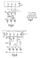
- Figure 3 accordingly shows one example of a multi-temperature indicating arrangement.
- Figure 3 only shows the relevant parts of the arrangement which differ from those shown in Figure 1, the remaining parts of the circuit being the same as shown in Figure 1.
- two further LEDs L3 and L4 are provided which are respectively connected to outlets 0 3 and 0 4 of counter CT.
- the thermostat is adjustable to any one of three temperatures and includes two ganged 3-position switches SW1 and SW2 coupled thereto such that the thermostat switches at 120°C when the switch is in the one-dot position, 160°C when in the two-dot position, and 210°C when in the three-dot position.
- switch SW1 The one-dot, two-dot, and three-dot contacts of switch SW1 are connected to outputs O2, 0 3 , and 0 4 respectively of counter CT, these outputs being respectively connected to LED L2 and to two additional LEDs L3 and L4 which are connected to the neutral rail via respective resistors R15 and R16.
- the arm of switch SW1 is connected to the inverting input of gate A and also to the neutral rail via a resistor R17. In each of its three positions, switch SW2 connects capacitor C3 to the DC rail.
- switch SW2 connects capacitor C3 to the power rail
- counter CR is always reset automatically in the manner described above when power is applied. Similarly, it is reset each time the setting of the switch is changed.
- counter CT is reset by switch SW2 as described above and then counts the operating cycles of thermostat TH.
- Counter CT then illuminates LED L2 as described above but can not take a further count step to illuminate LED L3, whereupon further counting is inhibited by the "high" signal on output 0 3 of the counter being applied via switch SW1 to the AND-gate A.
- LED L3 therefore remains illuminated, and the arrangement cycles at the required temperature (160°) until the position of switches SW1 and SW2 is changed or until the power supply is removed.
- FIG. 4 shows one way in which the lamps could be arranged around a rotatable adjusting knob K which controls the switches and the thermostat setting and can be set to any one of the three'dot' settings.
- the LEDs are arranged so that each one is adjacent a respective position of the knob pointer F which indicates the particular 'dot' temperature.
- This layout gives a particularly easily-read indication to the user that the apparatus concerned, for example a smoothing iron, is operating at the selected temperature.
- the LED L1 of Figure 1 is not necessary but can, of course, be provided if required in any arrangement in accordance with the invention.
- each of the LEDs L1, L2 and L3 is located on a panel adjacent its respective 'dot' temperature indication.
- the number of LEDs illuminated at any one time corresponds with the number of dots representing the particular temperature at which a smoothing iron is operating.
- An example of such an arrangement is shown in Figure 6 which only differs from Figure 3 in that additional diodes D7 to D11 have been added.
- LED L2 With a "high" signal on output O2, LED L2 is illuminated as before, though it is now in series with isolating diode D9.
- LED L3 is illuminated via diode D10 and LED L2 is illuminated via diodes D10 and D7.
- a "high" signal on output 0 4 will illuminate LED L4 via diode D11, L3 via diodes D11 and D8 in series, and L2 via diodes D11, D8 and D7 in series.
- the number of lamps illuminated at any one time corresponds to the number of dots in the international standard for electric irons at which the arrangement is operating.
- Several alternative layouts for the LED's are of course possible, but a particularly clear layout is shown in Figure 7 in which the LEDs form part of the international symbol for ironing temperatures.
- the three 'dots' of the symbol, shown as circles within the iron representation in Figure 7, are the three LEDs of Figure 6.
- LEDs L2, L3, and L4 could be arranged in sequence from left to right, for example, or L2 may be the central LED. In the latter case, a closer representation of the symbol for the one-dot temperature is obtained-i.e. the illuminated dot is central in the iron symbol.
- Figure 8 shows one way in which this can be achieved, namely that only one output of counter CT is used to illuminate the required LED and the LED concerned is selected by the switch SW1.
- the remaining parts of the circuit are as given in Figure 1 modified by Figure 3.
- LED 1 has also been added as in Figure 1 so that, say, a red “not ready” lamp (LED1) is illuminated when the arrangement is warming up and a respective green “ready” lamp is illuminated for the particular one of the three (or more) available temperatures.
- LED1 a red “not ready” lamp (LED1) is illuminated when the arrangement is warming up and a respective green “ready” lamp is illuminated for the particular one of the three (or more) available temperatures.
- temperatures can be indicated as is required and this is limited only by practical considerations such as the cost and the number of indicators that can conveniently be provided.
- an electric smoothing iron only three temperatures are required to cover the whole of the required ironing range and so no more than three indicators (apart from a "waiting" indicator L1 if required) are required.
- so-called water cookers in which the cooking is effected by water at a selectable one of a number of temperatures, a larger number may be required.
- the wash water may be controlled at any one of a plurality of temperatures-again as covered by the international washing standard.
- An arrangement according to the invention can be used to provide a visual indication of when the wash water is heated to the specified temperature.
- any convenient form of visual indicator may, of course, be used but there is a preference for LEDs because of their low current and voltage requirements, low price, small size, and good visibility.
- Other forms may of course, alternatively be used--such as filament lamps (pea-bulbs) or neon indicators. The former require too high a current and the latter require too high a voltage to allow them to be driven directly from the majority of integrated circuit counters, however.
- Suitable LEDs for L1 to L4 are, for example, Mullard Type CQW10A (Red) and suitable values for the components shown in the embodiments are:-Resistors (kilohms) Capacitors
Landscapes
- Engineering & Computer Science (AREA)
- Physics & Mathematics (AREA)
- General Physics & Mathematics (AREA)
- Automation & Control Theory (AREA)
- Textile Engineering (AREA)
- Control Of Temperature (AREA)
- Testing And Monitoring For Control Systems (AREA)
Claims (11)
Applications Claiming Priority (2)
| Application Number | Priority Date | Filing Date | Title |
|---|---|---|---|
| GB08401506A GB2153166A (en) | 1984-01-20 | 1984-01-20 | Temperature control and indicating arrangement |
| GB8401506 | 1984-01-20 |
Publications (2)
| Publication Number | Publication Date |
|---|---|
| EP0152971A1 EP0152971A1 (de) | 1985-08-28 |
| EP0152971B1 true EP0152971B1 (de) | 1989-04-19 |
Family
ID=10555272
Family Applications (1)
| Application Number | Title | Priority Date | Filing Date |
|---|---|---|---|
| EP85200034A Expired EP0152971B1 (de) | 1984-01-20 | 1985-01-16 | Temperatursteuerung und Anzeigeeinrichtung |
Country Status (6)
| Country | Link |
|---|---|
| US (1) | US4585926A (de) |
| EP (1) | EP0152971B1 (de) |
| JP (1) | JPS60159917A (de) |
| CA (1) | CA1232048A (de) |
| DE (1) | DE3569645D1 (de) |
| GB (1) | GB2153166A (de) |
Families Citing this family (10)
| Publication number | Priority date | Publication date | Assignee | Title |
|---|---|---|---|---|
| US4712095A (en) * | 1986-08-01 | 1987-12-08 | Georgis Ii Paul F | Remote temperature alarm for stoves |
| KR900009189Y1 (ko) * | 1988-06-17 | 1990-10-06 | 삼성전자 주식회사 | 전자조리기의 출력 제어회로 |
| US5576919A (en) * | 1993-06-01 | 1996-11-19 | U.S. Philips Corporation | Spark suppressor circuit for protection of an electrical switch, and electrical thermal appliance comprising such a circuit |
| IT1311289B1 (it) | 1999-12-28 | 2002-03-12 | Miller Europe Spa | Termostato, in particolare per elettrodomestici. |
| USD462481S1 (en) | 2001-07-31 | 2002-09-03 | Conair Corporation | Handle |
| US7351939B2 (en) * | 2004-03-19 | 2008-04-01 | Whirlpool Corporation | Toaster |
| FR2875138B1 (fr) * | 2004-09-15 | 2008-07-11 | Mallinckrodt Dev France Sa | Procede de regulation pour un humidificateur chauffant |
| FR2899247B1 (fr) * | 2006-03-31 | 2008-05-09 | Rowenta Werke Gmbh | Fer a vapeur comportant un indicateur d'entartrage |
| CN101828871A (zh) * | 2010-05-20 | 2010-09-15 | 刘昭利 | 节电、保健型饮水机控制装置 |
| CN115279218B (zh) * | 2020-03-11 | 2025-09-02 | 日本烟草国际股份有限公司 | 气溶胶产生装置、方法及其控制电路系统 |
Family Cites Families (8)
| Publication number | Priority date | Publication date | Assignee | Title |
|---|---|---|---|---|
| US2518503A (en) * | 1945-05-04 | 1950-08-15 | Birtamn Electric Company | Electric iron |
| BE792859A (fr) * | 1972-03-08 | 1973-03-30 | Mefina Sa | Dispositif de reglage de la temperature de la plaque chauffanted'une presse a repasser electrique |
| US3882475A (en) * | 1972-12-04 | 1975-05-06 | Robert J Moore | Control of roofing procedure |
| US3852728A (en) * | 1973-10-29 | 1974-12-03 | Ark Les Switch Corp | Stove warning device |
| US4189855A (en) * | 1977-06-27 | 1980-02-26 | Scovill Manufacturing Company | Electric pressing iron having indicating ready light |
| US4124793A (en) * | 1978-01-13 | 1978-11-07 | Metaframe Corporation | Aquarium water heater |
| US4240077A (en) * | 1978-03-02 | 1980-12-16 | United Brands Company | Thermostat |
| US4347430A (en) * | 1980-02-14 | 1982-08-31 | Michael Howard-Leicester | Vapor generator with cycling monitoring of conductivity |
-
1984
- 1984-01-20 GB GB08401506A patent/GB2153166A/en not_active Withdrawn
-
1985
- 1985-01-11 US US06/690,925 patent/US4585926A/en not_active Expired - Fee Related
- 1985-01-16 EP EP85200034A patent/EP0152971B1/de not_active Expired
- 1985-01-16 DE DE8585200034T patent/DE3569645D1/de not_active Expired
- 1985-01-17 JP JP60005136A patent/JPS60159917A/ja active Pending
- 1985-01-17 CA CA000472283A patent/CA1232048A/en not_active Expired
Also Published As
| Publication number | Publication date |
|---|---|
| US4585926A (en) | 1986-04-29 |
| GB8401506D0 (en) | 1984-02-22 |
| GB2153166A (en) | 1985-08-14 |
| JPS60159917A (ja) | 1985-08-21 |
| DE3569645D1 (en) | 1989-05-24 |
| CA1232048A (en) | 1988-01-26 |
| EP0152971A1 (de) | 1985-08-28 |
Similar Documents
| Publication | Publication Date | Title |
|---|---|---|
| US4282423A (en) | Deep fat fryer having a solid-state control circuit | |
| JP2815370B2 (ja) | ヒータ・エネルギ・カウンタを用いた温度センサ故障検出装置および方法 | |
| US3364338A (en) | Oven temperature control | |
| US7109444B2 (en) | Electronic control circuit for household appliances including humidifiers | |
| EP0152971B1 (de) | Temperatursteuerung und Anzeigeeinrichtung | |
| US3032636A (en) | Domestic heating appliance | |
| JPS6326979A (ja) | 電気オーブンの電気消費体の制御装置 | |
| US2654824A (en) | Control for electric ovens | |
| GB2135143A (en) | Electric heating appliance | |
| US2847553A (en) | Control for heating apparatus | |
| US4687910A (en) | Circuit for controlling and displaying cooking states of a rice cooker | |
| GB2267751A (en) | Cooking hob | |
| JP2981344B2 (ja) | 集合形加熱装置 | |
| US2785266A (en) | Electric range with automatic griddle attachment | |
| US2591849A (en) | Heating circuit control for electric appliances | |
| US4874929A (en) | Toaster oven/broiler with continuously energized indicator | |
| EP0932356B1 (de) | Regelbarer zeitschalter mit einem rc-oszillator mit einstellbarem widerstand, sowie brotröster ausgerüstet mit einem solchen zeitschalter | |
| GB2318502A (en) | Electric toasting machine with timing circuit | |
| US2900480A (en) | Electric range | |
| US2764662A (en) | Electric heating apparatus | |
| US3221142A (en) | Household cooking ovens incorporating warming and thawing systems | |
| CN220256257U (zh) | 一种电煮锅 | |
| EP0320157A1 (de) | Kontrollapparat für elektrisch geheizte Bettanlagen | |
| DE1068399B (de) | ||
| JPH0399614A (ja) | 炊飯器 |
Legal Events
| Date | Code | Title | Description |
|---|---|---|---|
| PUAI | Public reference made under article 153(3) epc to a published international application that has entered the european phase |
Free format text: ORIGINAL CODE: 0009012 |
|
| AK | Designated contracting states |
Designated state(s): DE FR GB IT SE |
|
| 17P | Request for examination filed |
Effective date: 19860110 |
|
| 17Q | First examination report despatched |
Effective date: 19880517 |
|
| RAP3 | Party data changed (applicant data changed or rights of an application transferred) |
Owner name: N.V. PHILIPS' GLOEILAMPENFABRIEKEN Owner name: PHILIPS ELECTRONIC AND ASSOCIATED INDUSTRIES LIMIT |
|
| GRAA | (expected) grant |
Free format text: ORIGINAL CODE: 0009210 |
|
| AK | Designated contracting states |
Kind code of ref document: B1 Designated state(s): DE FR GB IT SE |
|
| REF | Corresponds to: |
Ref document number: 3569645 Country of ref document: DE Date of ref document: 19890524 |
|
| ITF | It: translation for a ep patent filed | ||
| ET | Fr: translation filed | ||
| PLBE | No opposition filed within time limit |
Free format text: ORIGINAL CODE: 0009261 |
|
| STAA | Information on the status of an ep patent application or granted ep patent |
Free format text: STATUS: NO OPPOSITION FILED WITHIN TIME LIMIT |
|
| 26N | No opposition filed | ||
| PGFP | Annual fee paid to national office [announced via postgrant information from national office to epo] |
Ref country code: GB Payment date: 19901221 Year of fee payment: 7 |
|
| PGFP | Annual fee paid to national office [announced via postgrant information from national office to epo] |
Ref country code: FR Payment date: 19910118 Year of fee payment: 7 |
|
| PGFP | Annual fee paid to national office [announced via postgrant information from national office to epo] |
Ref country code: SE Payment date: 19910125 Year of fee payment: 7 |
|
| ITTA | It: last paid annual fee | ||
| PGFP | Annual fee paid to national office [announced via postgrant information from national office to epo] |
Ref country code: DE Payment date: 19910322 Year of fee payment: 7 |
|
| PG25 | Lapsed in a contracting state [announced via postgrant information from national office to epo] |
Ref country code: GB Effective date: 19920116 |
|
| PG25 | Lapsed in a contracting state [announced via postgrant information from national office to epo] |
Ref country code: SE Effective date: 19920117 |
|
| GBPC | Gb: european patent ceased through non-payment of renewal fee | ||
| PG25 | Lapsed in a contracting state [announced via postgrant information from national office to epo] |
Ref country code: FR Effective date: 19920930 |
|
| PG25 | Lapsed in a contracting state [announced via postgrant information from national office to epo] |
Ref country code: DE Effective date: 19921001 |
|
| REG | Reference to a national code |
Ref country code: FR Ref legal event code: ST |
|
| EUG | Se: european patent has lapsed |
Ref document number: 85200034.8 Effective date: 19920806 |