EP0152987A1 - Vorrichtung bestehend aus einem Rahmen aus Rohrstücken und Verbinder und die Verbinder dafür - Google Patents
Vorrichtung bestehend aus einem Rahmen aus Rohrstücken und Verbinder und die Verbinder dafür Download PDFInfo
- Publication number
- EP0152987A1 EP0152987A1 EP85200196A EP85200196A EP0152987A1 EP 0152987 A1 EP0152987 A1 EP 0152987A1 EP 85200196 A EP85200196 A EP 85200196A EP 85200196 A EP85200196 A EP 85200196A EP 0152987 A1 EP0152987 A1 EP 0152987A1
- Authority
- EP
- European Patent Office
- Prior art keywords
- face
- base
- arm
- recess
- coupling piece
- Prior art date
- Legal status (The legal status is an assumption and is not a legal conclusion. Google has not performed a legal analysis and makes no representation as to the accuracy of the status listed.)
- Granted
Links
Images


Classifications
-
- A—HUMAN NECESSITIES
- A47—FURNITURE; DOMESTIC ARTICLES OR APPLIANCES; COFFEE MILLS; SPICE MILLS; SUCTION CLEANERS IN GENERAL
- A47B—TABLES; DESKS; OFFICE FURNITURE; CABINETS; DRAWERS; GENERAL DETAILS OF FURNITURE
- A47B47/00—Cabinets, racks or shelf units, characterised by features related to dismountability or building-up from elements
- A47B47/0008—Three-dimensional corner connectors, the legs thereof being received within hollow, elongated frame members
-
- A—HUMAN NECESSITIES
- A47—FURNITURE; DOMESTIC ARTICLES OR APPLIANCES; COFFEE MILLS; SPICE MILLS; SUCTION CLEANERS IN GENERAL
- A47B—TABLES; DESKS; OFFICE FURNITURE; CABINETS; DRAWERS; GENERAL DETAILS OF FURNITURE
- A47B2220/00—General furniture construction, e.g. fittings
- A47B2220/11—Tripod parts
-
- A—HUMAN NECESSITIES
- A47—FURNITURE; DOMESTIC ARTICLES OR APPLIANCES; COFFEE MILLS; SPICE MILLS; SUCTION CLEANERS IN GENERAL
- A47B—TABLES; DESKS; OFFICE FURNITURE; CABINETS; DRAWERS; GENERAL DETAILS OF FURNITURE
- A47B2230/00—Furniture jointing; Furniture with such jointing
- A47B2230/01—Assemblies of strip sections, able to hold panels and corner parts for furniture
-
- F—MECHANICAL ENGINEERING; LIGHTING; HEATING; WEAPONS; BLASTING
- F16—ENGINEERING ELEMENTS AND UNITS; GENERAL MEASURES FOR PRODUCING AND MAINTAINING EFFECTIVE FUNCTIONING OF MACHINES OR INSTALLATIONS; THERMAL INSULATION IN GENERAL
- F16B—DEVICES FOR FASTENING OR SECURING CONSTRUCTIONAL ELEMENTS OR MACHINE PARTS TOGETHER, e.g. NAILS, BOLTS, CIRCLIPS, CLAMPS, CLIPS OR WEDGES; JOINTS OR JOINTING
- F16B12/00—Jointing of furniture or the like, e.g. hidden from exterior
- F16B12/44—Leg joints; Corner joints
- F16B2012/446—Leg joints; Corner joints with three-dimensional corner element, the legs thereof being inserted in hollow frame members
-
- F—MECHANICAL ENGINEERING; LIGHTING; HEATING; WEAPONS; BLASTING
- F16—ENGINEERING ELEMENTS AND UNITS; GENERAL MEASURES FOR PRODUCING AND MAINTAINING EFFECTIVE FUNCTIONING OF MACHINES OR INSTALLATIONS; THERMAL INSULATION IN GENERAL
- F16B—DEVICES FOR FASTENING OR SECURING CONSTRUCTIONAL ELEMENTS OR MACHINE PARTS TOGETHER, e.g. NAILS, BOLTS, CIRCLIPS, CLAMPS, CLIPS OR WEDGES; JOINTS OR JOINTING
- F16B2200/00—Constructional details of connections not covered for in other groups of this subclass
- F16B2200/67—Rigid angle couplings
-
- Y—GENERAL TAGGING OF NEW TECHNOLOGICAL DEVELOPMENTS; GENERAL TAGGING OF CROSS-SECTIONAL TECHNOLOGIES SPANNING OVER SEVERAL SECTIONS OF THE IPC; TECHNICAL SUBJECTS COVERED BY FORMER USPC CROSS-REFERENCE ART COLLECTIONS [XRACs] AND DIGESTS
- Y10—TECHNICAL SUBJECTS COVERED BY FORMER USPC
- Y10T—TECHNICAL SUBJECTS COVERED BY FORMER US CLASSIFICATION
- Y10T403/00—Joints and connections
- Y10T403/34—Branched
- Y10T403/341—Three or more radiating members
-
- Y—GENERAL TAGGING OF NEW TECHNOLOGICAL DEVELOPMENTS; GENERAL TAGGING OF CROSS-SECTIONAL TECHNOLOGIES SPANNING OVER SEVERAL SECTIONS OF THE IPC; TECHNICAL SUBJECTS COVERED BY FORMER USPC CROSS-REFERENCE ART COLLECTIONS [XRACs] AND DIGESTS
- Y10—TECHNICAL SUBJECTS COVERED BY FORMER USPC
- Y10T—TECHNICAL SUBJECTS COVERED BY FORMER US CLASSIFICATION
- Y10T403/00—Joints and connections
- Y10T403/34—Branched
- Y10T403/347—Polyhedral
-
- Y—GENERAL TAGGING OF NEW TECHNOLOGICAL DEVELOPMENTS; GENERAL TAGGING OF CROSS-SECTIONAL TECHNOLOGIES SPANNING OVER SEVERAL SECTIONS OF THE IPC; TECHNICAL SUBJECTS COVERED BY FORMER USPC CROSS-REFERENCE ART COLLECTIONS [XRACs] AND DIGESTS
- Y10—TECHNICAL SUBJECTS COVERED BY FORMER USPC
- Y10T—TECHNICAL SUBJECTS COVERED BY FORMER US CLASSIFICATION
- Y10T403/00—Joints and connections
- Y10T403/55—Member ends joined by inserted section
Definitions
- the invention relates to a device comprising a frame composed of lengths of tubing and coupling pieces interconnecting the same, each coupling piece having a cubical body provided on each outer face with a recess with undercut engaging rims for receiving a base part of an arm connected with a tubing and having complementary engaging rims in a manner such that the arm is fixed in place at least in the direction transverse of the outer face.
- each arm can be slipped laterally into a recess of an outer face.
- the outer faces of each coupling piece furthermore have a recess corresponding to the section of a tubing and adapted to receive one end of a tubing.
- the disadvantage of this known device is that the edge of the cubical body has to be larger than the width of a tubing so that the bodies of the coupling pieces project beyond the planes of the tubings. In this way mounting of panels in closing fashion in and on the device is rendered very difficult.
- the invention has for its object to provide a device of the kind set forth above, in which the outer faces of the coupling pieces and the tubings can be coplanar.
- the edge of the body is equal to the thickness of the tubings
- the body consists of two identical parts having a square head face, each part having complementary connecting means for joining a body part by a base face to the base face of the other body part in a direction transverse of the head face, whilst each side face has a recess which is accessible only from the base face for the base part of the arm and which forms, together with a corresponding recess in the other body part, the recess for receiving the base part of an arm.
- the base parts of the arms can be immovably fixed in the body when joining the body parts.
- each outer face for receiving the end of the tubing concerned is redundant so that the edge of the cubical body can be equal to the width of a tubing.
- the recesses in the head faces of each body part have to remain laterally accessible for the base part of an arm.
- an arm part arranged in a head face is fixed against displacement by the wall of the tubing on the side towards which the recess is open so that also the tubings connected with a head face are fixed against displacement in the body.
- a tubing on the side face towards which the recess in the head face is open is necessary.
- Each configuration of the coupling piece can thus be obtained, in which it is ensured that the arm parts and hence the tubings are fixed in place with respect to the body so that the cubical body may have an edge equal to the width of a tubing.
- the connecting means of the body part comprise two pins located near opposite corners of the base face and being at right angles thereto and bores extending from the base face into the body part near the other opposite corners, whilst the points of intersection of the centre lines of the pins and the bores with the base face determine a rectangle having sides extending parallel to the sides of the base face.
- the pins of one body part can snap into bores of a further body part, whilst the pins of the other body part snap into the bores of the first body part.
- the ends of the pins can be deformed in known manner so that the pins are fixed in the associated bores and the body parts are undetachably interconnected so that an integral coupling piece is obtained.
- a closing plate can be arranged in at least one recess of the coupling piece, in accordance with a further aspect of the invention, the head face of said plate coinciding with the side face concerned of the body in the mounted state.
- the closed piece has a closed appearance.
- the invention provides particular advantages when at least one of the lengths of tubing consists of two profiles divisible in the longitudinal direction, an associated arm is provided with engaging means co-operating with one of the profiles and the bases of the arms and the recesses have a square shape.
- Such divisible profiles which may be used for accommodating lighting fittings, can thus be connected in different rotational positions with the coupling piece by inserting the arm concerned in the rotational position concerned into the recess. In this way many tens of relatively different coupling pieces can be assembled from only two different parts in accordance with the invention.
- At least the arm base has a passage connecting the interior of a length of tubing with the interior of a coupling piece. It is thus possible to pass ducts, in particular electric conductors through the frame.
- At least the body parts and the arms of each coupling piece are preferably manufactured by spray-casting a hard aluminium alloy.
- the invention relates to and provides a further coupling piece and parts thereof apparently intended to form a device of the kind described above.
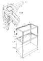
- the device shown in Fig. 1 is a show case comprising a frame 3 assembled from lengths of tubing 2 and coupling pieces 4 interconnecting said lengths of tubing 2.
- the show case 1 are arranged glass plates 6 disposed on lugs.
- the lower ends of the vertical tubings are provided with setting feet 8 for setting the show case 1 in a horizontal position.
- the tubings 2 hold lighting fittings 5 at a plurality of places.
- the consequences thereof for the frame 3 will be discussed hereinafter.
- the electric conductors for the lighting fittings 5 are passed through the tubings 2 and the coupling pieces 4.
- the lighting fittings are suitable low-voltage fittings and the foot 7 of the show case 1 comprises the required transformer with the required connecting elements for the separate fittings 5.
- the fittings 5 illuminate very nicely the objects exposed in the show case 1. When the show case is completely closed by glass, no troublesome mirror effect due to the light sources will occur in contrast to external illumination by spot lights.
- a coupling piece 4 comprises a cubical body 9 and a plurality of arms 11 projecting from side faces of the body 9 for engaging ends of the tubings 2.
- the ends of the tubings 2 engage the projecting arms with some clamping effect and can be fixed thereto with the aid of a set screw.
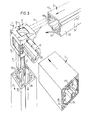
- Fig. 4 illustrates the way of assembling a coupling piece 2 embodying the invention.
- the body 9 of the coupling piece consists of two identical body parts 10.
- Each body part has mainly the shape of a rectangular parallelopiped having a square base face and a height equal to half the width.
- two body parts joined by their base faces form a cube.
- Each body part 10 is provided with complementary connecting means 25 by which two body parts 10 can be fixed to one another by their base faces.
- the connecting means 25 are formed by two pins 26 near opposite corners of the base face and bores 27 near the other opposite corners. From Fig. 4 it is apparent that the pins 26 and the bores 27 define a square. In order to permit of interconnecting two identical body parts it is, however, sufficient for the pins and the bores to define a rectangle having sides parallel to the sides of the base face.
- the pins of one body part 10 can thus be received in the bores 27 of the opposite body part 10.
- the pins 26 have a length such that in the assembled state of the two body parts 10 'they extend up to the head face of the end face concerned as is shown in Figs. 2 and 3. By deforming the end of the pin 26 in the bore 27 the body parts are firmly secured to one another.
- Each body part 10 has a recess 28 in its head face.
- a groove 29 is formed in the wall of the recess 28.
- the groove 29 adjoins a prolonged groove 30 extending towards a side face.
- the groove 29 and the recess 28 are accessible at 31 from a side face.
- Each side face of the body part 10 also has recesses 32.
- the recesses 32 are open towards the base face of the body part 10 and can form together with a corresponding recess 32 in the co-operating body part 10 a continuous recess.
- the recesses 32 have a groove 33.
- the recesses 28 and 32 have a square shape. They can receive the square, plate-shaped base 35 of an arm 11 in the groove 33 or 29. An arm can be slid from the access 31 into a recess 28 and from the base face into a recess 32 in the state in which the body parts 10 are still separated from one another.
- closing plates can be arranged in the recesses 28 and 32 not receiving arms.
- a square closing plate 13 is used, the rim 36 of which snaps into the groove 33.
- the head face 37 of the closing plate 13 coincides, in the mounted state, with the side face concerned of the body 9.
- a recess 28 in the head face of a body part can be filled with a closing plate 14 also having a complementary shape and being provided with a rim 38 snapping into the groove 29 and the prolonged groove 30.
- the head face 39 of the closing plate 14 coincides, in the mounted state, with the head face of the body part 10 concerned.
- the lengths of tubing 2 consist of two profiles 17, 18 divisible in the longitudinal direction.
- the lighting fittings 5 are mounted in the profile parts 18.
- the frame 3 is built up in a first instance without the profile parts 18.
- the coupling pieces are designed so that the arms 11 thereof are provided with engaging means co-operating with the profile part 17. These engaging means are formed by hook-like profiles 19 near the inner corner of the profile part 17 by co-operating recesses 20 in the arms 11.
- the electric conductors 12 can be arranged in place for the lighting fittings 5.
- each arm 11 has a passage 40 establishing a communication between the interior of a tubing 2 and the interior of a coupling piece.
- the electric conductors 12 can thus be very readily arranged at their places whilst the profile parts 18 have not yet been mounted. Subsequently the profile parts 18 with or without lighting fittings 5 are snapped into the associated profile parts 17.
- each arm 11 and the recesses in the body 9 have a square shape.
- the base of the arms and the recesses in the body may, however, have a shape different from the square.
- each arm can be used in two angular positions.
- the device embodying the invention is particularly suitable for specific uses such as the use described above with lighting fittings arranged in the tubings, the invention is not limited to this particular use.
- the invention is particularly advantageous in the case of relatively low production rates or when the number of variations of the coupling pieces is so great that a satisfactory control of stock and orders is no longer feasible.
Landscapes
- Mutual Connection Of Rods And Tubes (AREA)
- Earth Drilling (AREA)
- Supports For Pipes And Cables (AREA)
- Freezers Or Refrigerated Showcases (AREA)
- Furniture Connections (AREA)
- Packging For Living Organisms, Food Or Medicinal Products That Are Sensitive To Environmental Conditiond (AREA)
- Domestic Plumbing Installations (AREA)
- Microwave Tubes (AREA)
Priority Applications (1)
| Application Number | Priority Date | Filing Date | Title |
|---|---|---|---|
| AT85200196T ATE36741T1 (de) | 1984-02-17 | 1985-02-15 | Vorrichtung bestehend aus einem rahmen aus rohrstuecken und verbinder und die verbinder dafuer. |
Applications Claiming Priority (2)
| Application Number | Priority Date | Filing Date | Title |
|---|---|---|---|
| NL8400519 | 1984-02-17 | ||
| NL8400519A NL8400519A (nl) | 1984-02-17 | 1984-02-17 | Inrichting met uit buisstukken en koppelstukken samengesteld gestel en koppelstuk daarvoor. |
Publications (2)
| Publication Number | Publication Date |
|---|---|
| EP0152987A1 true EP0152987A1 (de) | 1985-08-28 |
| EP0152987B1 EP0152987B1 (de) | 1988-08-24 |
Family
ID=19843505
Family Applications (1)
| Application Number | Title | Priority Date | Filing Date |
|---|---|---|---|
| EP85200196A Expired EP0152987B1 (de) | 1984-02-17 | 1985-02-15 | Vorrichtung bestehend aus einem Rahmen aus Rohrstücken und Verbinder und die Verbinder dafür |
Country Status (8)
| Country | Link |
|---|---|
| US (1) | US4678359A (de) |
| EP (1) | EP0152987B1 (de) |
| JP (1) | JPS61501276A (de) |
| AT (1) | ATE36741T1 (de) |
| AU (1) | AU575628B2 (de) |
| DE (1) | DE3564605D1 (de) |
| NL (1) | NL8400519A (de) |
| WO (1) | WO1985003748A1 (de) |
Cited By (7)
| Publication number | Priority date | Publication date | Assignee | Title |
|---|---|---|---|---|
| EP0297400A1 (de) * | 1987-06-23 | 1989-01-04 | Eggersmann GmbH + Co. KG | Büro-Arbeitsplatz |
| AU628170B2 (en) * | 1989-05-09 | 1992-09-10 | Ilmar Pold | Improvements relating to connectors |
| WO1993017248A1 (de) * | 1992-02-20 | 1993-09-02 | USM U. Schärer Söhne AG | Vorrichtung zum verbinden von stab- und/oder plattenförmigen bauteilen |
| EP2317157A2 (de) | 2009-10-20 | 2011-05-04 | Francesc Orobitg Petit | Verbindungselement zum rechtwinkeligen Verbinden von zwei metallischen Profilen und System in welchem dieses Element verwendet wird |
| WO2017105334A1 (en) * | 2015-12-16 | 2017-06-22 | Flexlink Ab | Split connector and modular frame comprising such a split connector |
| WO2021140279A1 (en) * | 2020-01-10 | 2021-07-15 | Aicci Oy | Connector for a furniture frame, furniture frame, and furniture |
| US20210254857A1 (en) * | 2018-06-18 | 2021-08-19 | Munters Europe Aktiebolag | A connection device and a frame provided with such a device |
Families Citing this family (31)
| Publication number | Priority date | Publication date | Assignee | Title |
|---|---|---|---|---|
| US5499547A (en) * | 1991-09-04 | 1996-03-19 | Smc Kabushiki Kaisha | Actuator |
| JPH0574359U (ja) * | 1992-03-18 | 1993-10-12 | 積水樹脂株式会社 | 陳列用ケースの枠材連結具 |
| US5516225A (en) * | 1994-05-04 | 1996-05-14 | Kvols; Kevin | Corner connector and molding therefor |
| DE4439614C1 (de) * | 1994-11-05 | 1995-12-14 | Loh Kg Rittal Werk | Rahmengestell für einen Schaltschrank |
| US5524977A (en) * | 1995-02-24 | 1996-06-11 | Orawski; Walter | Security display case |
| DE29601355U1 (de) * | 1996-01-29 | 1997-06-05 | Frör, Werner, 91052 Erlangen | Verbindungsknoten für Baukonstruktionen |
| US5937584A (en) * | 1997-06-13 | 1999-08-17 | General Motors Corporation | Integral support for mounting of door module |
| IT1314302B1 (it) * | 1999-12-21 | 2002-12-09 | Abb Ricerca Spa | Intelaiatura di supporto per un armadio di quadro elettrico,e relativo armadio |
| US6962262B2 (en) * | 2003-02-10 | 2005-11-08 | Dennis Toma | Connecting corner for knock down racks |
| GB0414950D0 (en) * | 2004-07-05 | 2004-08-04 | Web M & E Products Ltd | Frame means |
| DE102006036988B4 (de) * | 2006-08-08 | 2015-10-01 | Universität Kassel | Stabtragwerk zur Bildung eines Rahmens, umfassend mehrere Knoten und die Knoten verbindende Stäbe |
| TWM317800U (en) * | 2007-03-16 | 2007-09-01 | Huei Tyng Entpr Co Ltd | Place rack |
| US7896177B1 (en) * | 2008-05-08 | 2011-03-01 | Toma Dennis R | Versatile support system and methods thereof |
| DE102008039852A1 (de) * | 2008-08-27 | 2010-03-04 | Technamation Technical Europe Gmbh | Verbindungssystem für Möbelbauteile |
| US8403431B2 (en) * | 2009-09-01 | 2013-03-26 | Emerson Network Power, Energy Systems, North America, Inc. | Telecommunications enclosures |
| CN102340942A (zh) * | 2010-07-19 | 2012-02-01 | 鸿富锦精密工业(深圳)有限公司 | 服务器机柜 |
| WO2012075536A1 (en) * | 2010-12-10 | 2012-06-14 | Haylin Systems Pty Ltd | Frame connection |
| BE1019767A3 (nl) | 2011-01-14 | 2012-12-04 | Brustor Nv | Zonwering. |
| EP2678571B1 (de) * | 2011-02-25 | 2015-04-01 | C E S Control Enclosure Systems GmbH | Eckverbinder für hohlprofile |
| JP2014126172A (ja) * | 2012-12-27 | 2014-07-07 | Tsubaki-Seiko Co Ltd | 金属フレーム組立体用の連結具、金属フレーム、金属フレーム組立体 |
| US9598852B2 (en) * | 2014-03-21 | 2017-03-21 | Murphy Reynolds O'NEAL | Construction system |
| US9578772B2 (en) | 2014-09-05 | 2017-02-21 | Emerson Network Power, Energy Systems, North America, Inc. | Cabinet frame enclosures, frame members and corresponding methods |
| ITUA20162429A1 (it) * | 2016-04-08 | 2017-10-08 | Goppion Spa | Vetrina museale con pianale portante |
| DE102017118912A1 (de) * | 2017-08-18 | 2019-02-21 | Maximilian Rüttiger | Bausatz zur Halterung von Elementen an einem Gegenstand |
| US10640969B2 (en) | 2018-02-17 | 2020-05-05 | BuildXGroup, Inc. | Cube coupling joint |
| JP2021032378A (ja) * | 2019-08-28 | 2021-03-01 | 株式会社Coba | ジョイント部材 |
| US11073328B1 (en) * | 2020-01-23 | 2021-07-27 | Bsh Home Appliances Corporation | Injection molded front frame corners for cooling appliances |
| DE202020106774U1 (de) * | 2020-11-25 | 2020-12-07 | Häfele GmbH & Co KG | Eckverbinder sowie Rahmen und Klappbett mit solch einem Eckverbinder |
| DE202021100478U1 (de) * | 2021-02-01 | 2022-05-03 | Schlüter-Systems Kg | Profilsystem |
| AU2021106516A4 (en) * | 2021-04-21 | 2021-11-04 | Rhino Rack Australia Pty Limited | Means of forming T-joint between extruded elements |
| USD1106508S1 (en) * | 2022-06-14 | 2025-12-16 | Spacecube IP Pty Ltd | Construction element |
Citations (4)
| Publication number | Priority date | Publication date | Assignee | Title |
|---|---|---|---|---|
| CH436610A (de) * | 1966-05-27 | 1967-05-31 | Contraves Ag | Gestell-Bauteilsatz |
| FR2262217A1 (en) * | 1974-02-22 | 1975-09-19 | Guillaumond Gabriel | Joining blocks used for cabinets or shelving - adapt to different methods of fixing |
| GB1497403A (en) * | 1975-07-31 | 1978-01-12 | Sloggett C | Framework members |
| DE3142283A1 (de) * | 1981-10-24 | 1983-05-11 | Reiner 7070 Schwäbisch Gmünd Moll | Bausatz fuer gestelle fuer den moebelbau |
Family Cites Families (10)
| Publication number | Priority date | Publication date | Assignee | Title |
|---|---|---|---|---|
| NL289719A (de) * | 1962-03-05 | 1965-06-10 | ||
| SE331261B (de) * | 1969-03-28 | 1970-12-14 | E Wennstroem | |
| US3752511A (en) * | 1971-06-04 | 1973-08-14 | Line Fast Corp | Container coupler |
| US3912410A (en) * | 1971-11-05 | 1975-10-14 | Giancarlo Pofferi | Demountable structural joint |
| DE2404088A1 (de) * | 1974-01-29 | 1975-09-04 | Rensch Eberhard | Raumteiler fuer wohnraeume, bueros, ausstellungsraeume, laeden o.dgl. |
| US4012153A (en) * | 1975-03-21 | 1977-03-15 | Pidgeon Martin J | Structural connection means |
| ZA761548B (en) * | 1976-03-12 | 1977-10-26 | Serbert Ind Ltd | Connector |
| FR2352202A1 (fr) * | 1976-05-21 | 1977-12-16 | Richier Sa | Dispositif destine a assurer la liaison des elements d'une charpente metallique |
| CH609214A5 (en) * | 1976-10-05 | 1979-02-28 | Escher Wyss Gmbh | Gravity drier for free-flowing material, in particular seed kernels |
| GB2070721B (en) * | 1980-03-03 | 1983-09-14 | Conforti M | Joint member for rods or tubes |
-
1984
- 1984-02-17 NL NL8400519A patent/NL8400519A/nl not_active Application Discontinuation
-
1985
- 1985-02-14 US US06/701,510 patent/US4678359A/en not_active Expired - Fee Related
- 1985-02-15 JP JP60500827A patent/JPS61501276A/ja active Pending
- 1985-02-15 AT AT85200196T patent/ATE36741T1/de not_active IP Right Cessation
- 1985-02-15 WO PCT/NL1985/000010 patent/WO1985003748A1/en not_active Ceased
- 1985-02-15 EP EP85200196A patent/EP0152987B1/de not_active Expired
- 1985-02-15 DE DE8585200196T patent/DE3564605D1/de not_active Expired
- 1985-02-15 AU AU39907/85A patent/AU575628B2/en not_active Ceased
Patent Citations (4)
| Publication number | Priority date | Publication date | Assignee | Title |
|---|---|---|---|---|
| CH436610A (de) * | 1966-05-27 | 1967-05-31 | Contraves Ag | Gestell-Bauteilsatz |
| FR2262217A1 (en) * | 1974-02-22 | 1975-09-19 | Guillaumond Gabriel | Joining blocks used for cabinets or shelving - adapt to different methods of fixing |
| GB1497403A (en) * | 1975-07-31 | 1978-01-12 | Sloggett C | Framework members |
| DE3142283A1 (de) * | 1981-10-24 | 1983-05-11 | Reiner 7070 Schwäbisch Gmünd Moll | Bausatz fuer gestelle fuer den moebelbau |
Cited By (8)
| Publication number | Priority date | Publication date | Assignee | Title |
|---|---|---|---|---|
| EP0297400A1 (de) * | 1987-06-23 | 1989-01-04 | Eggersmann GmbH + Co. KG | Büro-Arbeitsplatz |
| AU628170B2 (en) * | 1989-05-09 | 1992-09-10 | Ilmar Pold | Improvements relating to connectors |
| WO1993017248A1 (de) * | 1992-02-20 | 1993-09-02 | USM U. Schärer Söhne AG | Vorrichtung zum verbinden von stab- und/oder plattenförmigen bauteilen |
| EP2317157A2 (de) | 2009-10-20 | 2011-05-04 | Francesc Orobitg Petit | Verbindungselement zum rechtwinkeligen Verbinden von zwei metallischen Profilen und System in welchem dieses Element verwendet wird |
| WO2017105334A1 (en) * | 2015-12-16 | 2017-06-22 | Flexlink Ab | Split connector and modular frame comprising such a split connector |
| US10501928B2 (en) | 2015-12-16 | 2019-12-10 | Flexlink Ab | Split connector and modular frame comprising such a split connector |
| US20210254857A1 (en) * | 2018-06-18 | 2021-08-19 | Munters Europe Aktiebolag | A connection device and a frame provided with such a device |
| WO2021140279A1 (en) * | 2020-01-10 | 2021-07-15 | Aicci Oy | Connector for a furniture frame, furniture frame, and furniture |
Also Published As
| Publication number | Publication date |
|---|---|
| AU575628B2 (en) | 1988-08-04 |
| DE3564605D1 (en) | 1988-09-29 |
| WO1985003748A1 (en) | 1985-08-29 |
| NL8400519A (nl) | 1985-09-16 |
| AU3990785A (en) | 1985-09-10 |
| JPS61501276A (ja) | 1986-06-26 |
| EP0152987B1 (de) | 1988-08-24 |
| ATE36741T1 (de) | 1988-09-15 |
| US4678359A (en) | 1987-07-07 |
Similar Documents
| Publication | Publication Date | Title |
|---|---|---|
| EP0152987B1 (de) | Vorrichtung bestehend aus einem Rahmen aus Rohrstücken und Verbinder und die Verbinder dafür | |
| US4421434A (en) | Clamp members | |
| US4840440A (en) | Corner construction apparatus and method | |
| CN1131691C (zh) | 展览会设施或商店设施组装用的型材配置 | |
| US6652117B2 (en) | Light casing | |
| US4535580A (en) | Screw slot runner system | |
| US8550656B2 (en) | Selectively-extendable modular lighting fixture | |
| US8733851B2 (en) | Modular furniture system | |
| US6634149B2 (en) | Track assembly for cleanroom wall system | |
| US4628421A (en) | Strip lighting | |
| PL178551B1 (pl) | Człon ramy do stojaka ramowego szafy rozdzielczej | |
| CA2708453A1 (en) | Housing formed from extruded panels | |
| CN107355671B (zh) | 一种拼装结构 | |
| EP2157357B1 (de) | Modulare Boden- oder Wandeinbauleuchte | |
| US5904018A (en) | System of structural elements, particularly for building internal walls | |
| US3803535A (en) | Adjustable mounting element for electrical connectors utilizing a pair of l-shaped members | |
| CN214504849U (zh) | 一种连接件及应用其的高精度任意定制大小拼接箱体 | |
| CN211115540U (zh) | 一种分体组合式铝合金门窗转角型材 | |
| JPH0617291U (ja) | 組立て要素支持体 | |
| CN223136593U (zh) | 一种型材组件 | |
| CN214615150U (zh) | 一种用于中空墙板的阴角安装辅助工具 | |
| CN221002502U (zh) | 一种门板的135°连接角码 | |
| CA1301235C (en) | Corner construction apparatus and method | |
| CA2709726A1 (en) | Joint for extruded panels | |
| JPS602831Y2 (ja) | 組立家具 |
Legal Events
| Date | Code | Title | Description |
|---|---|---|---|
| PUAI | Public reference made under article 153(3) epc to a published international application that has entered the european phase |
Free format text: ORIGINAL CODE: 0009012 |
|
| AK | Designated contracting states |
Designated state(s): AT BE CH DE FR GB IT LI LU NL SE |
|
| 17P | Request for examination filed |
Effective date: 19860228 |
|
| 17Q | First examination report despatched |
Effective date: 19870520 |
|
| RAP1 | Party data changed (applicant data changed or rights of an application transferred) |
Owner name: KEEN, EGBERT |
|
| ITF | It: translation for a ep patent filed | ||
| GRAA | (expected) grant |
Free format text: ORIGINAL CODE: 0009210 |
|
| AK | Designated contracting states |
Kind code of ref document: B1 Designated state(s): AT BE CH DE FR GB IT LI LU NL SE |
|
| REF | Corresponds to: |
Ref document number: 36741 Country of ref document: AT Date of ref document: 19880915 Kind code of ref document: T |
|
| REF | Corresponds to: |
Ref document number: 3564605 Country of ref document: DE Date of ref document: 19880929 |
|
| ET | Fr: translation filed | ||
| PLBE | No opposition filed within time limit |
Free format text: ORIGINAL CODE: 0009261 |
|
| STAA | Information on the status of an ep patent application or granted ep patent |
Free format text: STATUS: NO OPPOSITION FILED WITHIN TIME LIMIT |
|
| 26N | No opposition filed | ||
| PGFP | Annual fee paid to national office [announced via postgrant information from national office to epo] |
Ref country code: GB Payment date: 19920131 Year of fee payment: 8 Ref country code: BE Payment date: 19920131 Year of fee payment: 8 |
|
| PGFP | Annual fee paid to national office [announced via postgrant information from national office to epo] |
Ref country code: AT Payment date: 19920205 Year of fee payment: 8 |
|
| PGFP | Annual fee paid to national office [announced via postgrant information from national office to epo] |
Ref country code: SE Payment date: 19920206 Year of fee payment: 8 |
|
| PGFP | Annual fee paid to national office [announced via postgrant information from national office to epo] |
Ref country code: FR Payment date: 19920217 Year of fee payment: 8 |
|
| PGFP | Annual fee paid to national office [announced via postgrant information from national office to epo] |
Ref country code: CH Payment date: 19920225 Year of fee payment: 8 |
|
| PGFP | Annual fee paid to national office [announced via postgrant information from national office to epo] |
Ref country code: DE Payment date: 19920227 Year of fee payment: 8 |
|
| ITTA | It: last paid annual fee | ||
| PGFP | Annual fee paid to national office [announced via postgrant information from national office to epo] |
Ref country code: NL Payment date: 19920229 Year of fee payment: 8 |
|
| PGFP | Annual fee paid to national office [announced via postgrant information from national office to epo] |
Ref country code: LU Payment date: 19921231 Year of fee payment: 8 |
|
| PG25 | Lapsed in a contracting state [announced via postgrant information from national office to epo] |
Ref country code: LU Free format text: LAPSE BECAUSE OF NON-PAYMENT OF DUE FEES Effective date: 19930215 Ref country code: GB Effective date: 19930215 Ref country code: AT Effective date: 19930215 |
|
| PG25 | Lapsed in a contracting state [announced via postgrant information from national office to epo] |
Ref country code: SE Effective date: 19930216 |
|
| PG25 | Lapsed in a contracting state [announced via postgrant information from national office to epo] |
Ref country code: LI Effective date: 19930228 Ref country code: CH Effective date: 19930228 Ref country code: BE Effective date: 19930228 |
|
| EPTA | Lu: last paid annual fee | ||
| BERE | Be: lapsed |
Owner name: KEEN EGBERT Effective date: 19930228 |
|
| PG25 | Lapsed in a contracting state [announced via postgrant information from national office to epo] |
Ref country code: NL Effective date: 19930901 |
|
| GBPC | Gb: european patent ceased through non-payment of renewal fee |
Effective date: 19930215 |
|
| NLV4 | Nl: lapsed or anulled due to non-payment of the annual fee | ||
| PG25 | Lapsed in a contracting state [announced via postgrant information from national office to epo] |
Ref country code: FR Effective date: 19931029 |
|
| REG | Reference to a national code |
Ref country code: CH Ref legal event code: PL |
|
| PG25 | Lapsed in a contracting state [announced via postgrant information from national office to epo] |
Ref country code: DE Effective date: 19931103 |
|
| REG | Reference to a national code |
Ref country code: FR Ref legal event code: ST |
|
| EUG | Se: european patent has lapsed |
Ref document number: 85200196.5 Effective date: 19930912 |