EP0153027A2 - Aufzeichnungs- und Wiedergabesystem für Farb-Video-Signale - Google Patents
Aufzeichnungs- und Wiedergabesystem für Farb-Video-Signale Download PDFInfo
- Publication number
- EP0153027A2 EP0153027A2 EP85300473A EP85300473A EP0153027A2 EP 0153027 A2 EP0153027 A2 EP 0153027A2 EP 85300473 A EP85300473 A EP 85300473A EP 85300473 A EP85300473 A EP 85300473A EP 0153027 A2 EP0153027 A2 EP 0153027A2
- Authority
- EP
- European Patent Office
- Prior art keywords
- signal
- color
- phase
- quadrature
- recording
- Prior art date
- Legal status (The legal status is an assumption and is not a legal conclusion. Google has not performed a legal analysis and makes no representation as to the accuracy of the status listed.)
- Withdrawn
Links
Images


Classifications
-
- H—ELECTRICITY
- H04—ELECTRIC COMMUNICATION TECHNIQUE
- H04N—PICTORIAL COMMUNICATION, e.g. TELEVISION
- H04N9/00—Details of colour television systems
- H04N9/79—Processing of colour television signals in connection with recording
- H04N9/80—Transformation of the television signal for recording, e.g. modulation, frequency changing; Inverse transformation for playback
- H04N9/82—Transformation of the television signal for recording, e.g. modulation, frequency changing; Inverse transformation for playback the individual colour picture signal components being recorded simultaneously only
Definitions
- This invention relates to a recording and reproducing system for color video signals, and more particularly to an improved chroma signal recording and reproducing system which minimizes deviation of hues from the original as well as that of color saturation from the original and eliminates drop-out or missing of color information, thereby ensuring a high quality of reproduced pictures.
- a subcarrier is subjected to quadrature two-phase balanced modulation by two color difference signals to obtain a modulated chrominance signal commonly used in the NTSC system or PAL system, the frequency band of the chrominance signal being then converted into that lower than the FM band of a luminance signal, and this low-band converted chrominance signal is superposed on the FM luminance signal to be recorded together with the luminance signal.
- the low-band converted chrominance signal is separated from the reproduced signal to be then restored to the original high-band chrominance signal by a frequency converter.
- the low-band conversion type exhibits the following merits (a-1) to (a-4) among others.
- a-4 As the carrier chrominance signal is provided by modulation according to an AM mode, no beat interference occurs even when adjoining two tracks are scanned simultaneously by the magnetic head in the playback mode, and crosstalk can be easily eliminated by means of phase shift (PS) or phase inversion (PI). Thus, this type is suitable for guardband-less recording.
- PS phase shift
- PI phase inversion
- the low-band conversion type has demerits listed below.
- the reference carrier fails to completely follow up the time base variation resulting in deviation of hue from the original, even when, an APC circuit is incorporated to produce the reference carrier on the basis of the color burst signal.
- FM frequency modulation
- This color-difference line-sequential FM type exhibits the following advantages (c-1), (c-2).
- the color-difference line-sequential FM type has the following disadvantages of (d-1), (d-2).
- the present invention aims to provide a recording and reproducing system for color video signal which eliminates drop-out of color information, as experienced with the color-difference line-sequential FM type, without widening the occupied frequency band, and which reduces deviations of hue and color saturation to less than those experienced with the low-band conversion type even in the presence of a time base variation and a level variation, thereby ensuring reproduction of high quality pictures.
- a color video signal recording system comprising means for producing a quadrature two-phase balance-modulated color signal by subjecting a subcarrier to quadrature two-phase balanced modulation by two color signals, means for producing a demodulation-purpose reference phase signal which has the same frequency as that of the subcarrier and which is to be frequency-interleaved with the quadrature two-phase balance-modulated color signal, means for multiplexing the quadrature two-phase balance-modulated color signal and the demodulation-purpose reference phase signal together with a carrier luminance signal, and means for recording them.
- a system for reproducing a color video signal recorded on a medium the color video signal being provided by multiplexing a quadrature two-phase balance-modulated color signal obtained by subjecting a subcarrier to quadrature two-phase balanced modulation by two color signals and a demodulation-purpose reference phase signal which has the same frequency as that of the subcarrier and which is to be frequency-interleaved with the quadrature two-phase balance-modulated color signal, together with a carrier luminance signal, means for separating the carrier luminance signal, the quadrature two-phase balance-modulated color signal and the reference phase signal from the demodulated signal, and means for demodulating the quadrature two-phase balance-modulated color signal on the basis of the separated reference phase signal.
- a continuous reference phase signal for synchronous detection is previously multiplexed with the quadrature two-phase balance-modulated color signal to be recorded. Since the reproduced reference phase signal is also affected by a time base variation similarly as the reproduced quadrature two-phase balance-modulated color signal, this reproduced reference phase signal is utilized for demodulation of the color signal, so that the time base variations can be cancelled to eliminate hue deviation.
- the frequency fr of the reference phase signal is selected to be equal to the subcarrier frequency fc of the quadrature two-phase balance-modulated color signal so as not to widen the occupied frequency band and to cause the time base variation occurring in the reference phase signal to coincide with that of the quadrature two-phase balance-modulated color signal as much as possible.
- the phase of, for example, the reference phase signal is inverted at a time interval of 1H for the purpose of frequency interleaving of the two signals.
- an APC circuit must comprise of burst signals, which feature determines the performance in respect of the time based variation.
- the continuous reference phase signal eliminates the need for APC, and the quadrature two-phase balance-modulated color signal and the reference phase signal share the same time base variation, thereby proving sufficiently resistant against time based variation.
- the embodiments of the present invention to be described make up a magnetic video recording and reproducing apparatus.
- color difference signals R-Y and B-Y are used as two color signals.
- the symbol Y designates a luminance signal, and symbols R-Y and B-Y color difference signals respectively.
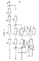
- Reference numbers 1, 2, 3 and 4 denote addition circuits; 5 and 6 balanced modulators for the quadrature two-phase balanced modulation; 7 and 8 an oscillator for generating the subcarrier and a 90° phase shifter respectively; 9 a synchronizing signal generator; 10 an offset voltage generator for producing the reference phase signal; 11 an index pulse generator; 12 an FM or PM angle modulator; 13 a recording amplifier; 14 a recording magnetic head; 15, 16, 17 and 18 low-pass filters; and 19 a high-pass filter.
- reference numbers in Fig. 2 respectively denote the following: 20 a reproducing magnetic head; 21 a high-pass filter for separating the luminance signals; 22 a limiter; 23 an angle demodulator; 24 a low-pass filter for separating the composite signal including the reference phase signal and the quadrature two-phase balance-modulated color signal; 25 a 1H delay and line; 26 an addition circuit; and 27 a subtraction circuit. These 25, 26 and 27 separate the reference phase signal and the quadrature two-phase balance-modulated color signal.
- Reference number 28 denote an AGC circuit; 29 a circuit for detecting the level of the reference phase signal; 30 and 31 synchronous detection circuits each using a balanced modulator; 32 and 33 lowpass filters; 34 an inversion circuit; 35 a limiter; and 36 a +90° phase shifter. These 34, 35 and 36 produce a carrier used for synchronous detection.
- Reference number 37 denote a horizontal synchronizing signal separation circuit; 38 an inversion pulse generator; 39 a PLL circuit; 40 a burst signal separation gate; and 41 a gate pulse generator. These 38, 39, 40 and 41 control the inversion circuit 34.
- Reference number 42 denote an addition circuit; 43 an encoder; and 44 a 3.58MHz oscillator. These 42, 43 and 45 produce an NTSC signal.
- the balance-modulated wave of one of the color difference signals or color difference signal R-Y is given by and that of the other color difference signal B-Y is given by
- the composite signal E BB (t) of these two signals provides the quadrature two-phase balance-modulated color signal as follows:
- any method may be employed for multiplexing the reference phase signal.
- an offset voltage is added to one of the color difference signals, i.e. B-Y, to realize multiplexing and frequency interleaving. More precisely, in response to the output of the subcarrier generator 7, the synchronizing signal generator 9 generates a synchronizing pulse signal 9a having a period of 1H as shown in Fig. 3(a), and in response to the pulse signal 9a, the offset voltage generator 10 generates a rectangular voltage signal whose amplitude is inverted between +K and -K at a time interval of 1H as shown in Fig. 3(b). Such an offset voltage signalfK is added in the addition circuit 4 to the color difference signal B-Y. Consequently,the result of synthesis of the output of the two balanced modulators 5 and 6 provides a,composite signal Ec(t) expressed as follows: i where K is a constant.
- the third member, ⁇ K sinwct, on the right represents the continuous reference phase signal.
- an index pulse signal tK as shown in Fig. 3(c) is added to the other color difference signal R-Y. It will be seen that the index pulse signal ⁇ K appears in the horizontal blanking period HBLK and has its polarity inverted at a time interval of 1H.
- the offset voltage signal ⁇ K is added to the color difference signal B-Y because red color requires a greater dynamic range than blue from the visual viewpoint. However, this offset voltage signal ⁇ K may theoretically be added to any of the color difference signals.
- any desired identification method employed in, for example, the color-difference line-sequential FM type of recording and reproduction may be utilized.
- the composite signal Ec(t) composed of the quadrature two-phase balance-modulated color signal E BB (t) and the reference phase signal ⁇ K sinwc(t) is then multiplexed with the carrier luminance signal Ey(t) which is an output from an angular modulator 12, and recorded in a magnetic recording medium such as a magnetic disk or tape by the magnetic head 14.
- E M (t) is expressed as follows: where Ey(t) is the voltage signal wave of Y.
- the output of a reproducing magnetic head 20 is passed through a high pass filter 21 and a low pass filter 24 after being amplified.
- the carrier luminance signal Ey(t) appears at the output of the high-pass filter 21, while the composite signal E c (t) composed of the quadrature two-phase balance-modulated color signal and the reference phase signal appears at the output of the low-pass filter 24.
- the carrier luminance signal Ey(t) is applied to a limiter 22 where level variation is eliminated, and then demodulated by an angle demodulator 23 depending on FM or PM.
- the composite signal E c (t) is separated into the quadrature two-phase balance-modulated color signal E BB (t) and the reference phase signal Ksinwct by a separation circuit of comb filter type composed of a 1H delay line 25, an addition circuit 26, and a subtraction circuit 27.
- a separation circuit of comb filter type composed of a 1H delay line 25, an addition circuit 26, and a subtraction circuit 27.
- the composite signal E ci+1 (t) corresponding to an (i+l)th horizontal scanning line becomes as follows:
- the equation (6) can be replaced by the following equation (9):
- the output signal of the 1H delay line 25 is added in the addition circuit 26 to the input signal to compute the addition of the equation (9) and the equation (7), the following relation (10) holds:
- the quadrature two-phase balance-modulated color signal can be separated.
- the synchronous detection signal +2Ksinwct is obtained having the same polarity as that of the separated quadrature two-phase balance-modulated color signal. If the timing of polarity inversion goes wrong, the demodulated color difference signals will have the opposite polarities resulting in a color error.
- an inversion control pulse signal 46 whose polarity is inverted at a time interval of 1H at an inversion pulse generator 38 is generated from an inversion pulse generator 38 on the basis of the detected phase difference signal 45 appearing from the PLL circuit 39 so as to control the switching operation of the inversion circuit 34 by the inversion control pulse signal 46. The operation is described in further detail below, and the index pulse signal superposed on the color difference signal R-Y during recording is utilized for this purpose.
- a limiter 35 is provided to prevent occurrence of level variations in the synchronous detection signal.
- the horizontal synchronizing signal is separated and extracted from the reproduced luminance signal in a synchronizing separation circuit 37 and is applied to a gate pulse generator 40 which generates a gate pulse signal appearing in the horizontal blanking period HBLK as shown in Fig. 3(d).
- This gate pulse signal is utilized to separate and extract the burst signal during the horizontal blanking period from the composite signal E c (t) appearing at the output of the low-pass filter 24. Since the burst signal is composed of the reference phase signal Ksinwct and the balance-modulated wave tK coswct of the index pulse signal, its phase changes at a time interval of 1H although its angular frequency is wc.
- a PLL circuit 39 includes a phase difference detector 39a, a phase compensation circuit 39b and a voltage controlled oscillator (VCO) 39c.
- VCO voltage controlled oscillator
- the PLL circuit 39 In response to the application of the burst signal sin(wct ⁇ ), the PLL circuit 39 generates a signal sinwct, and the output 45 of its phase difference detector 39a has a waveform shown in Fig. 3(f).
- the inversion circuit 34 Since the polarity of the detected phase difference signal 45 having such a waveform changes in correspondence with that of the index-pulse signal, the inversion circuit 34 operates with accurate timing when the inversion control pulse signal 46 generated from the pulse generator 38 has a rectangular waveform whose polarity is inverted at a time interval of 1H as shown in Fig. 3(g).
- the quadrature two-phase balance-modulated color signal is controlled of its level by the AGC circuit 28 which in turn is controlled by the output signal of the level detector 29 which envelope-detects the reference phase signal outputted from the subtractor 27. Since the reference phase signal is a continuous wave, it is possible to achieve a complete AGC. Further, since the reference phase signal is recorded in multiplex with the quadrature two-phase balance-modulated color signal and its frequency is the same as that of the subcarrier, its phase change, if any, attributable to a time base variation that may occur in the course of recording and reproduction is almost the same as that of the color signal.
- the demodulated color difference signals R-Y and B-Y are not adversely affected by the time base variation, and the hue deviation attributable to the tine base variation is minimized.
- the luminance signal Y and the two color difference signals R-Y, B-Y thus demodulated are applied to a unit such as a picture display unit.
- the subcarrier of 3.58 MHz produced by an oscillator 44 is applied to an encoder 43 in which the carrier of 3.58 MHz is subjected to quadrature two-phase balance modulation by the two color difference signals R-Y and B-Y, and the so-called carrier chrominance signal thus obtained is superposed on the luminance signal to output NTSC signal.
- the reference phase signal required for demodulation is frequency-interleaved and multiplexed as a continuous signal.
- the reference phase signal has the same variation despite the time base variation, and enables cancellation during demodulation as well as a complete AGC based on the reference phase signal.
- the polarity of reference phase signal is inverted at a time interval of 2H to frequency-interleave the reference phase signal with the quadrature two-phase balance-modulated color signal.
- the recording system is the. same as that shown in Fig. 1 except for generation of the offset voltage and index pulse signal.
- a demodulating circuit section 47 in the reproducing system shown in Fig. 2 is preferably modified to a structure as shown in Fig. 6.
- Fig. 7 shows the relation between the offset voltage and the index pulse signal.
- the synchronous detection signal can be separated as well.
- the color difference signals B-Y can be sequentially demodulated when the output signal of the addition circuit 26 is directly used for the synchronous detection of the output signal of the subtraction circuit 27, the polarity of the signals B-Y becomes inverted at a time interval of 2H, resulting in a color error. Therefore, the polarity of the output signal of the addition circuit 26 is inverted at a time interval of 2H in the inversion circuit 34 to provide the B-Y demodulation signal.
- the phase of the output signal of the inversion circuit 34 is delayed by 90° in the phase shifter 36, and such a signal is used to synchronously detect the output signal of the subtraction circuit 27. When the inversion circuit 34 operates with wrong timing, a color error results.
- the inversion control pulse signal 46 applied to the inversion circuit 34 is produced as described below.
- the offset voltage superposed on the color difference signal B-Y during recording is changed over between +K and -K at a time interval of 2H as shown in Fig. 7(b), and the index pulse signal superposed on the color difference signal R-Y is also changed over between +K and -K at a time interval of 2H as shown in Fig. 7(c).
- the gate circuit 41 applying the burst signal to the PLL circuit 39 is triggered by a timing pulse signal having a pulse period of 2H as shown in Fig. 7(d). Operation is otherwise the same as described with reference to Figs. 1 to 3 when n is an odd number.
- color information can entirely be recorded without partial drop-out of information as in the color-difference line-sequential FM type recording and reproduction, and a time base variation or a level variation, if any, does not substantially lead to the deviation of hue or color saturation of the low-band conversion type recording and reproduction. Therefore, a color video signal of high picture quality can be recorded and reproduced. While the foregoing description refers to application of the present invention to a magnetic picture recording / reproducing apparatus the present invention is equally applicable to recording and reproduction of still and moving pictures. The present invention is also applicable to various kinds of color video signal recording systems such as an optical video disk apparatus.
- the inclined azimuth arrangement is used for guardband-less recording.
- the inclined azimuth arrangement can also be employed in the present invention system.
- phase modulation (PM) of the luminance signal Y the techniques disclosed in Japanese Patent Publication No. 56-51406 (1981) and Japanese Patent Application Laid-open No. 53-41126 (1978) may be utilized.
- the conditions are also such that the phases of the center frequency of the PM luminance signal are aligned on the adjacent tracks, the center frequencies of the quadrature two-phase balance-modulated color signal are aligned on the adjacent tracks, and the phase inversions (o, ⁇ ) of the reference phase signal at the time interval of 1H or 2H are aligned on the adjacent tracks of the magnetic recording medium.
- the color video signal satisfying the above conditions is recorded at a high recording density in a guardband-less fashion or partly overlapping fashion, two or more tracks are scanned by the reproducing head, the color video signal can be reproduced without beat interference, crosstalk or out-of-synchronization by virtue of the strong vertical correlation between adjacent horizontal scanning lines in the color video signal.
Landscapes
- Engineering & Computer Science (AREA)
- Multimedia (AREA)
- Signal Processing (AREA)
- Processing Of Color Television Signals (AREA)
Applications Claiming Priority (2)
| Application Number | Priority Date | Filing Date | Title |
|---|---|---|---|
| JP9447/84 | 1984-01-24 | ||
| JP59009447A JPS60153692A (ja) | 1984-01-24 | 1984-01-24 | カラ−映像信号の記録再生方式 |
Publications (2)
| Publication Number | Publication Date |
|---|---|
| EP0153027A2 true EP0153027A2 (de) | 1985-08-28 |
| EP0153027A3 EP0153027A3 (de) | 1987-05-20 |
Family
ID=11720545
Family Applications (1)
| Application Number | Title | Priority Date | Filing Date |
|---|---|---|---|
| EP85300473A Withdrawn EP0153027A3 (de) | 1984-01-24 | 1985-01-24 | Aufzeichnungs- und Wiedergabesystem für Farb-Video-Signale |
Country Status (3)
| Country | Link |
|---|---|
| US (1) | US4668997A (de) |
| EP (1) | EP0153027A3 (de) |
| JP (1) | JPS60153692A (de) |
Cited By (2)
| Publication number | Priority date | Publication date | Assignee | Title |
|---|---|---|---|---|
| EP0144080A3 (de) * | 1983-11-30 | 1988-01-27 | Fuji Photo Film Co., Ltd. | Aufzeichnungs- und Wiedergabesystem für ein Farbvideosignal |
| DE4200221A1 (de) * | 1992-01-08 | 1993-07-15 | Thomson Brandt Gmbh | Videorecorder |
Families Citing this family (7)
| Publication number | Priority date | Publication date | Assignee | Title |
|---|---|---|---|---|
| DE3687492T2 (de) * | 1985-02-04 | 1993-08-05 | Matsushita Electric Ind Co Ltd | Videosignalprozessor. |
| US5732186A (en) * | 1986-06-20 | 1998-03-24 | Canon Kabushiki Kaisha | Image signal recording/reproducing apparatus having special-effects-processing capability |
| JPS63108888A (ja) * | 1986-10-27 | 1988-05-13 | Canon Inc | カラ−ビデオ信号再生装置 |
| US4941055A (en) * | 1986-12-09 | 1990-07-10 | Canon Kabushiki Kaisha | Recording apparatus with improved S/N ratio |
| DE3919225C2 (de) * | 1989-06-13 | 1994-04-14 | Samsung Electronics Co Ltd | Tiefband-Umwandlungsschaltung |
| KR920002273B1 (ko) * | 1989-07-08 | 1992-03-20 | 삼성전자 주식회사 | 원격 pll을 이용한 직각 변복조 방식 및 회로 |
| TW331692B (en) * | 1997-05-09 | 1998-05-11 | Ind Tech Res Inst | An improved image encoder and generator of auxiliary carrier signal |
Family Cites Families (8)
| Publication number | Priority date | Publication date | Assignee | Title |
|---|---|---|---|---|
| GB1275307A (en) * | 1969-07-12 | 1972-05-24 | Sony Corp | Magnetic recording and reproducing system |
| DE2110104B1 (de) * | 1971-03-03 | 1972-05-04 | Licentia | Aufzeichnungsverfahren für ein Farbfernsehsignal |
| GB1497865A (en) * | 1973-12-28 | 1978-01-12 | Sony Corp | Magnetic recording and/or reproducing apparatus |
| NL7402692A (nl) * | 1974-02-28 | 1975-09-01 | Philips Nv | Kleurentelevisiesysteem. |
| DE2619027C2 (de) * | 1976-04-30 | 1984-10-18 | Robert Bosch Gmbh, 7000 Stuttgart | Fernsehaufnahmesystem |
| JPS5953754B2 (ja) * | 1977-09-26 | 1984-12-26 | 松下電器産業株式会社 | カラ−テレビジヨン信号の記録再生方式 |
| US4520401A (en) * | 1982-04-16 | 1985-05-28 | Victor Company Of Japan, Ltd. | Digital video signal recording system and reproducing apparatus |
| JPS60117985A (ja) * | 1983-11-30 | 1985-06-25 | Fuji Photo Film Co Ltd | カラ−映像信号の記録再生方式 |
-
1984
- 1984-01-24 JP JP59009447A patent/JPS60153692A/ja active Pending
-
1985
- 1985-01-23 US US06/694,042 patent/US4668997A/en not_active Expired - Fee Related
- 1985-01-24 EP EP85300473A patent/EP0153027A3/de not_active Withdrawn
Cited By (2)
| Publication number | Priority date | Publication date | Assignee | Title |
|---|---|---|---|---|
| EP0144080A3 (de) * | 1983-11-30 | 1988-01-27 | Fuji Photo Film Co., Ltd. | Aufzeichnungs- und Wiedergabesystem für ein Farbvideosignal |
| DE4200221A1 (de) * | 1992-01-08 | 1993-07-15 | Thomson Brandt Gmbh | Videorecorder |
Also Published As
| Publication number | Publication date |
|---|---|
| JPS60153692A (ja) | 1985-08-13 |
| EP0153027A3 (de) | 1987-05-20 |
| US4668997A (en) | 1987-05-26 |
Similar Documents
| Publication | Publication Date | Title |
|---|---|---|
| US4743977A (en) | VTR having magnetic-head array capable of recording/reproducing signals of a plurality of recording systems | |
| US4233621A (en) | Method and apparatus for recording and reproducing a color-aligned line-sequential color video signal | |
| EP0289046B1 (de) | Vorrichtung zum Ermitteln von Zeitbasisschwankungen für einen Videobandrecorder | |
| US4668997A (en) | Recording and reproducing system for color video signal | |
| US4123774A (en) | Color signal encoding methods and apparatus for video recording and playback | |
| US4077046A (en) | System for recording and/or reproducing a video signal | |
| US4695899A (en) | Recording and reproducing system employing balanced modulation for color video signal | |
| US4051517A (en) | Hybrid sequential and carrier encoded color television transmission method and circuits | |
| GB1591922A (en) | Magnetic recording and reproducing system | |
| US4266241A (en) | Color signal encoding methods and apparatus for video recording and playback | |
| US4980779A (en) | Information signal recording and/or reproducing apparatus for correcting time variations | |
| US3749835A (en) | Continuous signal producing system | |
| US5077616A (en) | Video recorder with increased bandwidth recording | |
| US4193085A (en) | Apparatus for removing jitter in color television signal | |
| US4115820A (en) | System for reproducing a video signal | |
| US5598274A (en) | Image signal recording and reproducing system | |
| CA1045710A (en) | Apparatus for reproducing color video signals | |
| JPS6126875B2 (de) | ||
| JPH0720262B2 (ja) | 映像信号記録再生装置 | |
| KR880000412Y1 (ko) | 칼러 영상신호 기록장치 | |
| EP0104068B1 (de) | Farbvideosignal-Aufzeichnungsgerät | |
| CA2073519C (en) | Magnetic reproduction apparatus | |
| JP2569584B2 (ja) | カラ−映像信号変換方法 | |
| KR820000874B1 (ko) | 비디오 디스크 시스템용 칼라화면정보 레코드 재생장치 | |
| JPS5816397B2 (ja) | 搬送色信号の再生方法 |
Legal Events
| Date | Code | Title | Description |
|---|---|---|---|
| PUAI | Public reference made under article 153(3) epc to a published international application that has entered the european phase |
Free format text: ORIGINAL CODE: 0009012 |
|
| AK | Designated contracting states |
Designated state(s): DE FR GB |
|
| PUAL | Search report despatched |
Free format text: ORIGINAL CODE: 0009013 |
|
| AK | Designated contracting states |
Kind code of ref document: A3 Designated state(s): DE FR GB |
|
| 17P | Request for examination filed |
Effective date: 19871120 |
|
| 17Q | First examination report despatched |
Effective date: 19880315 |
|
| STAA | Information on the status of an ep patent application or granted ep patent |
Free format text: STATUS: THE APPLICATION IS DEEMED TO BE WITHDRAWN |
|
| 18D | Application deemed to be withdrawn |
Effective date: 19891003 |
|
| RIN1 | Information on inventor provided before grant (corrected) |
Inventor name: SAKAKI, NAOAKIC/O FUJI PHOTO FILM Inventor name: NAGANO, MASAHIKOC/O FUJI PHOTO FILM |