EP0153103B1 - Sod harvesting machine - Google Patents
Sod harvesting machine Download PDFInfo
- Publication number
- EP0153103B1 EP0153103B1 EP85300843A EP85300843A EP0153103B1 EP 0153103 B1 EP0153103 B1 EP 0153103B1 EP 85300843 A EP85300843 A EP 85300843A EP 85300843 A EP85300843 A EP 85300843A EP 0153103 B1 EP0153103 B1 EP 0153103B1
- Authority
- EP
- European Patent Office
- Prior art keywords
- sod
- frame
- harvesting machine
- machine according
- knife
- Prior art date
- Legal status (The legal status is an assumption and is not a legal conclusion. Google has not performed a legal analysis and makes no representation as to the accuracy of the status listed.)
- Expired
Links
- 238000003306 harvesting Methods 0.000 title claims description 22
- 210000003128 head Anatomy 0.000 description 7
- 238000005096 rolling process Methods 0.000 description 3
- 230000000694 effects Effects 0.000 description 2
- 229910000831 Steel Inorganic materials 0.000 description 1
- 210000004761 scalp Anatomy 0.000 description 1
- 239000010959 steel Substances 0.000 description 1
Images

Classifications
-
- A—HUMAN NECESSITIES
- A01—AGRICULTURE; FORESTRY; ANIMAL HUSBANDRY; HUNTING; TRAPPING; FISHING
- A01G—HORTICULTURE; CULTIVATION OF VEGETABLES, FLOWERS, RICE, FRUIT, VINES, HOPS OR SEAWEED; FORESTRY; WATERING
- A01G20/00—Cultivation of turf, lawn or the like; Apparatus or methods therefor
- A01G20/10—Pre-cultivated sod or turf; Apparatus therefor
- A01G20/12—Apparatus for cutting sods or turfs
Definitions
- This invention relates to an improved sod harvesting machine.
- Sod harvesting machines as shown in Canadian patent 843,808 entitled “Sod Cutting Apparatus” and issued on June 9,1970 to G. J. Brouwer have been used for some years. Such sod harvesting machines have proven very successful in practice, but they have a disadvantage.
- the disadvantage is that the entire sod harvesting machine, including the sod cutting head and the conveyor, are pivoted as a rigid unit to the support and propulsion vehicle by front and rear pivots whose axes are aligned in the rearwardly and upwardly slanting line. It has been found that under certain conditions this arrangement did not adequately follow small irregularities in the ground and would sometimes tend to scalp very thin sod.
- the invention provides a sod harvesting machine adapted for travel forwardly along a path of travel and having:
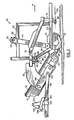
- Fig. 1 shows a sod harvesting machine generally indicated at 10.
- the sod harvesting machine 10 is essentially the same as that shown in the above-mentioned Canadian patent, except for the pivoting sod cutting head to be described. Since the invention relates to the pivoting mechanism, and since the basic mechanism for cutting sod and conveying it upwardly and rearwardly is well known, and is described, for example, in the above-mentioned Canadian patent, such sod cutting and conveying mechanism will here be described only briefly.
- the sod harvesting machine 10 is adapted for travel forwardly along a path of travel indicated by arrow A, to undercut a strip of sod 12 (Fig. 2) and to convey the cut strip upwardly and rearwardly along a conveyor 14.
- the sod harvesting machine 10 includes a sod cutting head 16 having a frame 18.
- the frame 18 is pivotally mounted (by means to be described) to a rear frame 20 which supports the conveyor 14 and which extends upwardly and rearwardly from the sod cutting head 16.
- the rear frame 20 is adapted to be mounted to a support and propulsion vehicle such as a tractor, a wheel of which is indicated at 22 in Fig. 3.
- the frame 18 of the sod cutting head 16 includes a pair of laterally spaced side members 24 having rear sections 26 which slant upwardly and rearwardly. Ths side members 24 are joined at their front by a front cross-member 28, and at their rear (at the tops of the slanting sections 26) by a rear cross-member 30. The side members 24 are also joined intermediate their legnth by a mid cross-member 32.
- a roller 34 for rolling the sod to be cut is transversely mounted between the side members 24 by pillow blocks 36.
- a rod cutting knife 38 having side cutting blades 40 and an undercutting blade 42 extending between the side cutting blades, is mounted immediately behind and below the roller 34 to cut the edges and beneath a strip of sod.
- the knife 38 is mounted by a pair of arms 44 which extend upwardly and are supported at their upper ends by a cross shaft 46 eccentrically connected to bearings 48 at the upper ends of the arms 44.
- the cross shaft 46 is mounted in pillow blocks 50 supported on raised members 52 which form part of the head frame 18.
- the cross shaft 46 is normally clamped by clamps 54 which can be loosened so that handle 56 can be moveed to adjust the angular position of the cross shaft, thereby raising or lowering the arms 44. This raises or lowers the cutting knife 38, thereby adjusting the thickness of the sod being cut.
- the arms 44 are reciprocated forwardly and rearwardly in the direction of arrow B by conventional driving means (not shown but shown and described in the above-mentioned Canadian patent) to undercut below and at the edges of a strip of sod 12 as indicated in Fig. 2.
- the strip of sod 12 is periodically severed laterally by a conventional cross-cut blade, not shown but which may be mounted on the head 16 in a manner similar to that shown in the above-mentioned Canadian patent.
- the cross cut blade is typically, as shown on that patent, activated by a cam (not shown) carried by shaft 59 pivotally mounted on the frame 18.
- the cut sod 12 is guided rearwardly from the cutting knife 38 by a set of parallel rearwardly extending conventional guide strips 58 located just behind the knife 38.
- the strips 58 are supported by arms 60 connected to the knife support arms 44, essentially as shown in said Canadian patent.
- the cut sod emerging from the guide strips 58 is caught by the conveyor 14 and conveyed upwardly and rearwardly to a station (not shown) on the harvester where it is rolled, slabbed, or otherwise dealt with as desired.
- a set of flexible steel rods 62 overlie the conveyor 14 near its lower end and prevent the cut sod from curling over and rolling back into the sod cutting head 16.
- the rods 62 are connected to a transverse rod 64 mounted on the side frame rear sections 26.
- the sod cutting head 16 is mounted on the rear frame 20 as follows.
- the rear frame 20 includes a pair of main channel side members 66 having side plates 68 bolted to their lower ends. Welded to the side plates are upwardly and forwardly extending plates 70, to which are connected forwardly and downwardly extending side box members 72.
- a generally V-shaped front cross member 74 is connected to the fronts of the box members 72.
- a downwardly extending plate 76 Welded to the center of the front cross member 74 is a downwardly extending plate 76.
- the plate 76 lies just ahead of a corresponding downwardly extending plate 78 welded to the mid-cross member 32 of the cutting head frame 16.
- a pivot shaft 80 extends between the two plates 76, 78 and has its axis 83 extending horizontally forwardly and rearwardly, thereby allowing pivoting of the sod cutting head 16 about the axis 82.
- the axis 82 of pivot shaft 80 is located as close to the ground as possible, to optimize tracking by the roller 34 and the sod cutting knife 38 of the contours of the ground.
- the rear of the sod cutting head 16 is pivoted to the rear frame 20 as follows.
- Two curved tracks 84 are welded one to each side of the rear cross member 30.
- Each track 84 is formed by a U-shaped channel having side flanges 86 and a connecting web 88.
- the tracks 84 are of circular contour and are mounted so that they have a common center of curvature on the axis 82 of the front pivot shaft 80.
- the inner opposing ends of the tracks 84 are closed by the flanges 86 which extend inwardly in a circular contour to meet each other in a curved closed end 90 (Fig. 3).
- Rollers 92 are located in the tracks 84, the rollers being rotatably mounted on shafts 94.
- the shafts 94 are fixed to downwardly extending plates 96 welded to a rear frame cross member 98.
- Cross member 98 is in turn welded to plates 70.
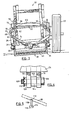
- the sod cutter head 16 In operation, as the roller 34 encounters small bumps which cause one side of the roller to rise with respect to the other (as shown in Fig. 3), the sod cutter head 16 is able to pivot about the front pivot shaft 80. At this time the curved tracks 84 move with respect to the rollers 92 in the circular path shown by dotted line 100 in Fig. 3.
- the curved tracks 84 and rollers 92 have the same effect as would a horizontal rear pivot shaft having its axis coincident with axis 82 of the front pivot shaft 80.
- the curved tracks 84 and rollers 92 thereby allow accurate tracking by the sod cutting head 16 of small irregularities in the ground.
- the plates 76, 78 are shown as overlying one another, in practice they are preferably spaced slightly apart as shown in Fig. 4 and are separated by a boss 102 welded to plate 76. Located within the boss 102 and plate 76 is a bushing 104 to provide a larger bearing surface for the front pivot.
- the pivot shaft 80 is constituted by a bolt 106 which extends through the bushing 104, through a hole in plate 78, and is held in place by a castle nut 108, and cotter pin 110.
- the sod cutting head 16 is prevented from moving forwardly or rearwardly with respect to the main frame by the front pivot shaft 80.
- the sod cutting head 16 tends to be forced rearwardly with respect to the rear frame 20, and such rearward forces are resisted by the connecting webs 88 which thrust rearwardly against the ends of the rollers 92.
- removable wear plates can be placed on the bottoms or tops of the track flanges 86 so that the entire track need not be replaced when wear occurs.
- the tracks 84 and rollers 92 are located well above the undercutting knife 38, room is provided to bring the forward end of the conveyor 14 close to the ground and close to the rear end of the cutting knife 38.
- the close proximity of the forward end of the conveyor 20 to the cutting knife 38 helps to ensure that the thin cut sod (which can be extremely fragile) can bridge the gap from the cutting knife to the conveyor with a minimal risk of being torn or misdirected.
- the rear pivots constituted by the curved tracks 84 and rollers 92 are well above the ground, they have, as mentioned, the effect of a single forwardly and rearwardly oriented horizontal pivot shaft located close to the ground and behind the knife 38, allowing accurate tracking by the sod cutting head of ground irregularities.
- the three point mounting arrangement shown provides good mechanical support for the sod cutting head 16 (which is subject to considerable stresses and continual vibration) and provides an extremely smooth pivoting action.
- the rear end of conveyor frame 20 is mounted by two side arms 118 (of which only one is shown, Fig. 5) pivotally connected at 112 to the frame 20 and pivotally connected at 114 to a frame member 116.
- the frame member 116 is connected to or forms part of the vehicle, not shown. This allows the front of the conveyor to be raised and lowered in the arc indicated by arrow C, Fig. 2.
- the front of the conveyor frame 20 is supported
- a lever arm 128 is fixed to each arm 120 through pivots 124, and the two lever arms 128 (of which only one is shown) are fixed to each other by a cross shaft 130.
- a hydraulic piston and cylinder 132 is connected between shaft 130 and an upstanding arm 134 fixed to beam 126. When piston and cylinder 132 is extended, side arms 128 are rotated counterclockwise about pivot 124 to raise the front end of frame 20, and with it head 16, clear of the ground.
- the pivot axis 82 about which the cutting head 16 pivots is preferably located centrally of the roller 34 and cutting knife 38, for best tracking of the ground contours. However, if the cutting head 16 is unbalanced (e.g. because there are hydraulic motors or other parts which make one side heavier than the other), then the pivot axis 82 will normally be located laterally at the side to side balance line of the cutting head 16. This balance position will not normally be more than a few inches offset from the lateral centre line of the head 16 (for a cutter which cuts e.g. an 18 inch (45.72 cm) wide strip of sod).
Landscapes
- Life Sciences & Earth Sciences (AREA)
- Environmental Sciences (AREA)
- Harvester Elements (AREA)
- Harvesting Machines For Root Crops (AREA)
- Soil Working Implements (AREA)
Applications Claiming Priority (2)
| Application Number | Priority Date | Filing Date | Title |
|---|---|---|---|
| CA447786A CA1217785A (en) | 1984-02-20 | 1984-02-20 | Pivot mechanism for sod cutting machine |
| CA447786 | 1984-02-20 |
Publications (2)
| Publication Number | Publication Date |
|---|---|
| EP0153103A1 EP0153103A1 (en) | 1985-08-28 |
| EP0153103B1 true EP0153103B1 (en) | 1988-10-26 |
Family
ID=4127234
Family Applications (1)
| Application Number | Title | Priority Date | Filing Date |
|---|---|---|---|
| EP85300843A Expired EP0153103B1 (en) | 1984-02-20 | 1985-02-08 | Sod harvesting machine |
Country Status (7)
| Country | Link |
|---|---|
| US (1) | US4621696A (da) |
| EP (1) | EP0153103B1 (da) |
| AU (1) | AU584601B2 (da) |
| CA (1) | CA1217785A (da) |
| DE (1) | DE3565751D1 (da) |
| DK (1) | DK161418C (da) |
| SE (1) | SE459545B (da) |
Families Citing this family (18)
| Publication number | Priority date | Publication date | Assignee | Title |
|---|---|---|---|---|
| NL192948C (nl) * | 1987-08-14 | 1998-06-03 | Vuuren Johannes Van | Inrichting voor het uit de bodem snijden van zoden. |
| US4892153A (en) * | 1988-04-08 | 1990-01-09 | Joe Cooling & Sons Inc. | Sod harvester |
| US4901507A (en) * | 1988-12-05 | 1990-02-20 | Cracraft Larry D | Pivoted deck lawnmower |
| CA2026473C (en) * | 1989-09-29 | 2002-01-15 | Stuart Paul Mail | Turf handling machine |
| US5069296A (en) * | 1990-06-05 | 1991-12-03 | Case Corporation | Pitch/tilt dozer |
| US5064000A (en) * | 1990-10-30 | 1991-11-12 | Bucyrus Equipment Co., Inc. | Method of and apparatus for cutting sod which rolls in a semi-flaccid sheet into sod roll |
| FR2713880B1 (fr) * | 1993-12-21 | 1996-03-08 | Express Gazon Sarl | Installation de coupe et de manutention de pavés de gazon. |
| US5626195A (en) * | 1995-07-10 | 1997-05-06 | Bucyrus Equipment Co.. Inc. | Sod harvesting system |
| US6244354B1 (en) | 1995-09-15 | 2001-06-12 | Harmelerwaard Patents B.V. | Device and process for cutting grass sods with a constant thickness from grass land |
| US5970690A (en) * | 1997-10-24 | 1999-10-26 | Ransomes America Corporation | Leveling apparatus for a cutting head of a mower |
| US6289660B1 (en) | 1997-12-31 | 2001-09-18 | Mtd Products Inc | Lawn edger having a side mounted debris deflector |
| US6571883B2 (en) * | 2001-06-04 | 2003-06-03 | Steiner Turf Equipment, Inc. | Sod harvester |
| CA2435929A1 (en) * | 2002-10-24 | 2004-04-24 | 1045929 Ontario Limited | Sod roll pre-starter |
| US7246669B2 (en) | 2002-10-29 | 2007-07-24 | Malcolm Cammack | Sod cutting device |
| US8469113B2 (en) * | 2009-08-20 | 2013-06-25 | Schiller Ground Care, Inc. | Earthworking machine |
| US8978779B2 (en) * | 2012-04-02 | 2015-03-17 | Firefly Equipment, Llc | Articulated cutting head and conveyor mount for sod harvesting machines |
| US9451739B2 (en) * | 2013-05-16 | 2016-09-27 | Dustin Miller | Agricultural undercut implements and methods |
| DE202023106960U1 (de) | 2023-11-24 | 2023-12-15 | Turfcom GmbH | Rollrasen-Erntemaschine und Erntemesser hierfür |
Family Cites Families (6)
| Publication number | Priority date | Publication date | Assignee | Title |
|---|---|---|---|---|
| US905985A (en) * | 1907-04-26 | 1908-12-08 | Jacob Clove | Automatic leveling combined harvester. |
| DE570108C (de) * | 1931-03-22 | 1933-02-11 | Bernhard Garrelfs | Schwingbar gelagerter Wagenkasten, insbesondere fuer Kraftfahrzeuge |
| US2709329A (en) * | 1951-12-26 | 1955-05-31 | David C Neal | Combine having side hill platform adjustments |
| US3509944A (en) * | 1966-06-27 | 1970-05-05 | Gerardus Johannes Brouwer | Sod cutting apparatus |
| US3590927A (en) * | 1969-09-29 | 1971-07-06 | Ryan Equipment Co | Mounting for sod-cutting machine |
| US3807504A (en) * | 1972-05-18 | 1974-04-30 | J Nunes | Sod harvesting apparatus |
-
1984
- 1984-02-20 CA CA447786A patent/CA1217785A/en not_active Expired
- 1984-03-27 US US06/594,000 patent/US4621696A/en not_active Expired - Fee Related
-
1985
- 1985-01-18 DK DK027085A patent/DK161418C/da not_active IP Right Cessation
- 1985-01-30 AU AU38171/85A patent/AU584601B2/en not_active Ceased
- 1985-02-08 DE DE8585300843T patent/DE3565751D1/de not_active Expired
- 1985-02-08 EP EP85300843A patent/EP0153103B1/en not_active Expired
- 1985-02-19 SE SE8500774A patent/SE459545B/sv not_active IP Right Cessation
Also Published As
| Publication number | Publication date |
|---|---|
| SE8500774L (sv) | 1985-08-21 |
| SE459545B (sv) | 1989-07-17 |
| AU3817185A (en) | 1985-08-29 |
| DK161418C (da) | 1991-12-16 |
| DE3565751D1 (en) | 1988-12-01 |
| SE8500774D0 (sv) | 1985-02-19 |
| EP0153103A1 (en) | 1985-08-28 |
| DK27085D0 (da) | 1985-01-18 |
| AU584601B2 (en) | 1989-06-01 |
| CA1217785A (en) | 1987-02-10 |
| DK27085A (da) | 1985-08-21 |
| US4621696A (en) | 1986-11-11 |
| DK161418B (da) | 1991-07-08 |
Similar Documents
| Publication | Publication Date | Title |
|---|---|---|
| EP0153103B1 (en) | Sod harvesting machine | |
| AU746994B2 (en) | Forestry machine swing-house leveling mechanism | |
| US7426817B2 (en) | Independent center reel position adjustment for an agricultural harvesting machine | |
| US9961832B2 (en) | Control of base cutter orientation in sugarcane harvesters | |
| US4553606A (en) | Sod cutting machine having split undercutting blade | |
| US3807504A (en) | Sod harvesting apparatus | |
| NL192948C (nl) | Inrichting voor het uit de bodem snijden van zoden. | |
| WO2007140520A1 (en) | Adjustable feed train for sugarcane harvester | |
| NL1001586C2 (nl) | Maaimachine. | |
| US6779610B2 (en) | Defective sod rejector and deflector | |
| CA1085626A (en) | Crop stubble masher for harvesting machine | |
| US11224166B2 (en) | Synchronizer for sugarcane knockdown roller | |
| US6397500B1 (en) | Trenching plow with reciprocating action | |
| JP4084529B2 (ja) | 汎用コンバインのセカンドモア | |
| US20050034439A1 (en) | Attachment for a sugarcane harvester | |
| US6112825A (en) | Mounting system for cutting head | |
| US4664447A (en) | Apparatus for removing roofing material | |
| US20020179308A1 (en) | Sod harvester | |
| JPH11206213A5 (da) | ||
| AU2017265029B9 (en) | Synchronizer for sugarcane knockdown roller | |
| JP2605775Y2 (ja) | 収穫機における方向検出装置 | |
| JP2812422B2 (ja) | 根菜収穫機の尻根除去装置 | |
| JPH09252620A (ja) | 自走式根菜収穫機の尻尾切り装置 | |
| US1194359A (en) | Machine fob topping bests | |
| US1915675A (en) | Snowplow |
Legal Events
| Date | Code | Title | Description |
|---|---|---|---|
| PUAI | Public reference made under article 153(3) epc to a published international application that has entered the european phase |
Free format text: ORIGINAL CODE: 0009012 |
|
| AK | Designated contracting states |
Designated state(s): BE DE FR GB NL |
|
| 17P | Request for examination filed |
Effective date: 19860122 |
|
| 17Q | First examination report despatched |
Effective date: 19870319 |
|
| GRAA | (expected) grant |
Free format text: ORIGINAL CODE: 0009210 |
|
| AK | Designated contracting states |
Kind code of ref document: B1 Designated state(s): BE DE FR GB NL |
|
| REF | Corresponds to: |
Ref document number: 3565751 Country of ref document: DE Date of ref document: 19881201 |
|
| ET | Fr: translation filed | ||
| PLBE | No opposition filed within time limit |
Free format text: ORIGINAL CODE: 0009261 |
|
| STAA | Information on the status of an ep patent application or granted ep patent |
Free format text: STATUS: NO OPPOSITION FILED WITHIN TIME LIMIT |
|
| 26N | No opposition filed | ||
| PGFP | Annual fee paid to national office [announced via postgrant information from national office to epo] |
Ref country code: GB Payment date: 19970207 Year of fee payment: 13 |
|
| PGFP | Annual fee paid to national office [announced via postgrant information from national office to epo] |
Ref country code: FR Payment date: 19970213 Year of fee payment: 13 |
|
| PGFP | Annual fee paid to national office [announced via postgrant information from national office to epo] |
Ref country code: DE Payment date: 19970217 Year of fee payment: 13 |
|
| PGFP | Annual fee paid to national office [announced via postgrant information from national office to epo] |
Ref country code: NL Payment date: 19970218 Year of fee payment: 13 |
|
| PGFP | Annual fee paid to national office [announced via postgrant information from national office to epo] |
Ref country code: BE Payment date: 19970219 Year of fee payment: 13 |
|
| PG25 | Lapsed in a contracting state [announced via postgrant information from national office to epo] |
Ref country code: GB Free format text: LAPSE BECAUSE OF NON-PAYMENT OF DUE FEES Effective date: 19980208 |
|
| PG25 | Lapsed in a contracting state [announced via postgrant information from national office to epo] |
Ref country code: FR Free format text: THE PATENT HAS BEEN ANNULLED BY A DECISION OF A NATIONAL AUTHORITY Effective date: 19980228 Ref country code: BE Free format text: LAPSE BECAUSE OF NON-PAYMENT OF DUE FEES Effective date: 19980228 |
|
| BERE | Be: lapsed |
Owner name: BROUWER TURF EQUIPMENT LTD Effective date: 19980228 |
|
| PG25 | Lapsed in a contracting state [announced via postgrant information from national office to epo] |
Ref country code: NL Free format text: LAPSE BECAUSE OF NON-PAYMENT OF DUE FEES Effective date: 19980901 |
|
| GBPC | Gb: european patent ceased through non-payment of renewal fee |
Effective date: 19980208 |
|
| NLV4 | Nl: lapsed or anulled due to non-payment of the annual fee |
Effective date: 19980901 |
|
| PG25 | Lapsed in a contracting state [announced via postgrant information from national office to epo] |
Ref country code: DE Free format text: LAPSE BECAUSE OF NON-PAYMENT OF DUE FEES Effective date: 19981103 |
|
| REG | Reference to a national code |
Ref country code: FR Ref legal event code: ST |