EP0153174A2 - Isolierung von Mehrleiterkabeln - Google Patents
Isolierung von Mehrleiterkabeln Download PDFInfo
- Publication number
- EP0153174A2 EP0153174A2 EP85301038A EP85301038A EP0153174A2 EP 0153174 A2 EP0153174 A2 EP 0153174A2 EP 85301038 A EP85301038 A EP 85301038A EP 85301038 A EP85301038 A EP 85301038A EP 0153174 A2 EP0153174 A2 EP 0153174A2
- Authority
- EP
- European Patent Office
- Prior art keywords
- conductors
- sleeve
- void
- accordance
- conductor
- Prior art date
- Legal status (The legal status is an assumption and is not a legal conclusion. Google has not performed a legal analysis and makes no representation as to the accuracy of the status listed.)
- Ceased
Links
Images

Classifications
-
- H—ELECTRICITY
- H02—GENERATION; CONVERSION OR DISTRIBUTION OF ELECTRIC POWER
- H02G—INSTALLATION OF ELECTRIC CABLES OR LINES, OR OF COMBINED OPTICAL AND ELECTRIC CABLES OR LINES
- H02G15/00—Cable fittings
- H02G15/08—Cable junctions
- H02G15/10—Cable junctions protected by boxes, e.g. by distribution, connection or junction boxes
-
- H—ELECTRICITY
- H02—GENERATION; CONVERSION OR DISTRIBUTION OF ELECTRIC POWER
- H02G—INSTALLATION OF ELECTRIC CABLES OR LINES, OR OF COMBINED OPTICAL AND ELECTRIC CABLES OR LINES
- H02G15/00—Cable fittings
- H02G15/08—Cable junctions
Definitions
- This invention relates to a method of insulating multi-conductor, medium-voltage electrical power cables at locations where the cable insulation has been removed, and, in particular, to insulating a joint between such cables and to the resulting joint.
- Medium voltage is used herein to specify voltages in the range of about 1 to about 36 kilovolts (kV).
- Another method of insulating joints is to use a heat shrinkable enclosure such as that disclosed in U.S. Patent No. 4,383,131. This technique has been used with single core cables and with multi-conductor cable. When used with multi-conductor cables, each of the conductors of the cable is generally separately insulated and shielded. A heat shrinkable enclosure is then installed over the joint. Enclosing and insulating a joint by this method requires numerous steps to install the various insulating and shielding components.
- This invention relates to a method of using a heat-shrinkable enclosure to provide insulation between the conductors of insulate a joint between multi-conductor, medium-voltage power cables, which method provides the advantages of a resin filled system without the inconvenience and other disadvantages typically associated with such systems, while maintaining the advantages of ease of installation of heat-shrinkable systems without requiring individual insulation and shielding of each conductor.
- This invention provides a method of insulating the conductors of a multi-conductor, medium voltage power cable at a location where the cable insulation is removed, each of said cables having at least three conductors, said method comprising:
- Another aspect of this invention comprises a method of insulating a joint between multiple-conductor, medium voltage power cables, each of said cables having at least three conductors each surrounded by a dielectric layer a portion of which has been removed to expose an end region of the conductor, the conductors of one cable being connected to the corresponding conductors of a second such cable, said method comprises:
- a second void-filling material capable of flowing due to the pressure and/or heat exerted by the recovery of the sleeve may be positioned over the conductors prior to installation of the recoverable sleeve.
- the dimensionally recoverable sleeve is preferably a heat-shrinkable sleeve.
- the insert is preferably a polymeric material which does not melt at operating temperatures of the cable, including temperatures reached under fault conditions and is preferably coated with a first void-filling material which melts and flows during installation of the insulation to form a void-free interface between the insert and each conductor of the cable.
- the first and second void-filling materials may be the same or different materials and either may be of an insulating or a stress grading material.
- the dimensionally recoverable sleeve preferably has an inner insulating layer, which is preferably elastomeric, and an outer conductive polymeric layer. Such a sleeve may be formed by coextrusion or molding.
- a joint insulated by the method of this invention may also be provided with an outer protective jacket which may be applied as a dimensionally recoverable polymeric sleeve. Further protection of the joint may be provided by means of a liner, preferably of metal slats, positioned over the joint before installation of the outer protective jacket.
- This invention relates to insulating the conductors, or cores, of multi-conductor, medium voltage power cables at locations, such as joints between such cables, where the original cable insulation has been removed.
- the term conductor has been used in the specification and claims to refer to the current carrying element and can be the bare conductor or the conductor surrounded by primary insulation.
- the conductor plus primary insulation is generally referred to in the art as a core.
- Medium voltage A.C. power cables typically have three conductors but cable configurations containing additional conductors are known.
- medium voltage power cables is meant electrical cables which conduct electricity at voltages between about 1 kV and 36 kV. Such voltages are also referred to as distribution voltages.
- 11 kV belted cables are well known and generally contain three conductors each surrounded by oil-impregnated cable insulation with paper or jute filler surrounding the insulated conductors.
- a layer of belt insulation surrounds the wormings and a metallic sheath, e.g. of aluminum or lead, surrounds the belt layer.
- Armor wires, or other armoring may be provided on the outside of the metallic sheath.
- a protective jute or polymeric jacket is on the outside of the armor wire, if present, or the metallic sheath where there is no armor wiring.
- the conductors are exposed by removing the outer layers of the cable structure and the oil impregnated paper insulation surrounding each conductor.
- the conductors are generally of a highly conductive metal such as copper or aluminum.
- the conductors can be solid and can be circular, oval or sectored. Alternatively, the conductors can be made up of numerous metals strands forming what is known as stranded conductors.
- the conductors of the cables to be joined are connected together by a suitable connector.
- Typical connectors comprise a metal cylinder which are crimped down onto and/or soldered to the conductors.
- a preferred connector is that described in European Patent Application publication No. 125042A (US Patent Serial no. 598,557, filed April 9, 1984), the disclosure of which is incorporated herein by reference.
- Each conductor of the first multi-conductor cable is connected to a conductor of a second multi-conductor cable.
- the individual conductors and connectors may be provided with initial insulation by wrapping an insulating tape or placing an insulating sleeve around the exposed portion and an adjacent insulated portion of each conductor and the connector. This may be done using several individual sleeves, e.g. one sleeve over the connector and separate sleeves over the adjacent conductor regions.
- each exposed conductor portion and adjacent core section is insulated with a recovered dimensionally recoverable, preferably heat-shrinkable, polymeric sleeve.
- the polymeric sleeve is preferably of an oil resistant material, for example polyvinylidene fluoride, when the cables being jointed are oil-impregnated paper insulated cables.
- recoverable article is used herein to mean an article the dimensional configuration of which may be made substantially to change when subjected to some treatment.
- Heat-recoverable articles which recover when heated, are particularly preferred in the practice of this invention. Usually these articles recover, towards an original shape from which they have previously been deformed but the term “recoverable”, as used herein, also includes an article which adopts a new configuration, even if it has not been previously deformed.
- such articles comprise a heat-shrinkable sleeve made from a polymeric material exhibiting the property of elastic or plastic memory as described, for example, in U.S. Patents 2,027,962, 3,086,242 and 3,597,372.
- the original dimensionally heat-stable form may be a transient form in a continuous process in which, for example, an extruded tube is expanded, while hot, to a dimensionally heat-unstable form but, in other applications, a preformed dimensionally heat-stable article is deformed to a dimensionally heat-unstable form in a separate stage.
- the polymeric material may be cross-linked at any stage in the production of the article that will enhance the desired dimensional recoverability.
- One manner of producing a heat-recoverable article comprises shaping the polymeric material into the desired heat-stable form, subsequently cross-linking the polymeric material, heating the article to a temperature above the crystalline melting point or, for amorphous materials the softening point, as the case may be, of the polymer, deforming the article and cooling the article while in the deformed state so that the deformed state of the article is retained.
- application of heat will cause the article to assume its original heat-stable shape.
- an elastomeric member such as an inner tubular member is held in a stretched state by a second member, such as an outer tubular member, which, upon heating weakens and thus allows the elastomeric member to recover.
- Such articles comprise an elastomeric member held in a stretched state by a retaining member.
- the elastomeric member is retained in the stretched state until released from the retaining member by application of solvent or by mechanically breaking or removing the retaining member.
- Such articles comprise an elastomeric tube held in a stretched state by an outer tubular member to which it is adhered.
- Each connector is preferably insulated with a polymeric insulating layer.
- the insulating layer can be tape or a recovered dimensionally recoverable polymeric sleeve.
- a stress grading material is placed around the conductor prior to recovering the sleeve.
- the term "stress grading material” is used herein to mean a material which when applied to areas of high electrical stress, relieves or reduces the stress.
- the stress grading material preferably is a mastic or other polymeric material having an impedance in the range of about 1 X to 10 9 ohm-cm to about 5 X 10 9 ohm-cm, measured at 40-80 Hertz.
- the material can be applied over each connector in the form of a maleable filling compound, tape, sheet or the like.
- a preferred material that can be used is an epihalohydrin based composition such as that disclosed in U.S. Patent No. 4,378,463 to Senior et al the disclosure of which is incorporated herein by reference.
- the joint is insulated in accordance with the method of this invention.
- An insert is positioned between the conductors.
- the insert is shaped such that it lies between each of the conductors.
- the insert is in the shape of "Y".
- At least the surface of the insert comprises a first void-filling material which is capable of forming a void-free interface between the insert and each of the conductors.
- the insert should be sufficiently flexible to enable it to accommodate the configuration of the conductors in the cable.
- the insert should be of a material which does not melt at temperatures reached during installation of the heat recoverable sleeve or at temperatures reached during fault conditions of the cable.
- the insert serves to insulate the conductors of the joint from each other and to prevent them from migrating toward each other. If the insert melts, the conductors may not be kept separate from each other and if they touch when the cable is operating, premature failure of the joint may occur.
- the insert may be made from a material, such as a polymeric gel, as described below, capable of forming a void-free interface with each conductor.
- the insert comprises a material which itself is not a void-filling material but is coated with a first void-filling material.
- the insert is formed of a polymeric insulating material having a dielectric constant in the range of between about 2 to about 6, preferably about 2.5 to about 3.2.
- the insert may be formed of a polymeric gel or a polymeric material.
- a polymeric insert can be formed by conventional methods, such as extrusion, molding and the like.
- the insert can contain a metal layer, preferably embedded in the body of the insert, to electrically shield the conductors from one another.
- the first void-filling material which may be insulating or stress grading, is formed of a sealant such as a mastic or gel.
- a mastic is an adherent, cohesive sealing material capable of filling a gap between two components.
- a mastic can deform or yield plastically, that is, undergo viscous flow, both during application and in subsequent service at ambient temperatures.
- Mastics may consist of mixtures of substantially non-crystalline materials, for example, bituminous materials, elastomers, or thermoplastic polymers, and may contain insert fibrous or powdered fillers.
- gel refers to a swollen cross-linked polymeric material, for example, a matrix of cross-linked rubber containing oil.
- a preferred gel for use herein is that described in U.S. Application Serial No. 646,555, filed August 31, 1984, the disclosure of which is incorporated herein by reference.
- the void-filler is a thermoplastic material having a viscosity at 70°C of between about 1 X I0 3 to about 1 X 10 5 poise.
- the void-filling material melts and flows filling voids between the conductors and the insert.
- the void-filler can be applied to the insert by any convenient technique, for example as a maleable ("putty-like") material, as a tape, or the like.
- a second void-filling material can, and preferably is, applied around the conductors after the insert is positioned.
- This additional void-filler can be applied by any convenient technique.
- One method of applying the void-filler is to use it in the form of a tape and wrap one or more layers over the assembly of conductors plus insert.
- the second void-filler can be a sealant, grease, mastic or gel and can be the same or different than the first void-filling material discussed above.
- Another technique is to provide the second void-filler in the form of diamond-shaped profiles of a material which flows under heat and/or pressure. Each profile is positioned over the gap to adjacent conductors and extending between them. On installation of the recoverable sleeve over the assembly the pressure of the sleeve and/or heat, if applied to recover the sleeve, causes the void-filling material to flow around the conductors filling all voids.
- Additional stress control material such as that described above, is advantageously applied in areas subject to electrical stress.
- a dimensionally recoverable polymeric sleeve which may be in the form of a tube or sheet capable of being formed and held in the shape of a tube, is installed over the assembly after the insert and void-filling materials have been appropriately positioned.
- the heat recoverable sleeve has an inner insulating layer and an outer semi-conductive layer. The sleeve is positioned so that it overlaps the lead sheaths of the cables and is then recovered. The insulating and conductive layer can be-applied as separate heat recoverable sleeves, if desired.
- the outer conductive layer is electrically connected to the lead sheaths of the cables, for example by means of a metal mesh which extends across the sheath.
- the invention can also be used to insulate joints between shielded power cables.
- the method of enclosing joints between shielded cables disclosed in U.S. Patents No. 4,383,135 to Clabburn and 4,390,745 to Boettcher can be used.
- an outer protective jacket enclosing the entire joint can be applied.
- the protective jacket is a polymeric tubular article.
- the tubular article also is preferably installed as a dimensionally recoverable, preferably heat recoverable, tubular article or wraparound sleeve.
- Figure 1 illustrates positioning a sealant-coated insert between the conductors 2, 3 and 4 of a joint between cables 5 and 6.
- Figure 2 is a cross-sectional view of a joint insulated in accordance with this invention.
- Insert 1 has been positioned between conductors 2, 3 and 4.
- the surface of insert 1 comprises a coating, 7, of mastic.
- Diamond-shaped profiles 8, 9 and 10 of void-filling mastic compostion are postioned around the conductors.
- a heat-recoverable polymeric sleeve, 11, comprising an inner layer, 12, of insulating polymeric material and an outer layer, 13, of conductive polymeric material encloses the assembly.
- Figure 2 illustrates the joint just prior to recovery of the sleeve.
- the void-filling mastics of profiles 8, 9 and 10 and of coating 7 melt and flow filling substantially all voids between insert 1 and conductors 2, 3 and 4 and between the conductors themselves and the conductors and the recovered sleeve.
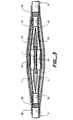
- Figure 3 is a longitudinal view of the completed joint.
- each of the connectors, conductors and adjacent insulation have been covered by initial insulation by means of polymeric sleeves 20, 21 and 22.
- the third set of conductors is blocked from view by insert 1.
- the void filling material, 23, is derived from the melting of coating, 7, and profiles 8, 9 and 10 shown in Figure 2.
- a metal braid, 24, and screen, 25, are positioned over the top of the recovered sleeve, 11, and are connected to metal sheath 26 of each of cables 5 and 6.
- a liner, 27, comprising elongate metal strips is positioned over the joint and connected to armor wires 28 of each cable. This provides continuity of the armoring of the cables.
- An outer protective jacket, 29, applied in the form of a heat-recoverable sleeve is installed over the joint and onto the outer jacket 30 of each cable.
- the invention has been described, as noted above, primarily with regard to its use in insulating a joint between 3-phase 11 kV belted cables.
- the invention is not to be construed as limited to such joints and can be used to insulate joints between shielded power cables, plastic insulated power, paper insulated draining and non-draining mass impregnated cables and can also be used to insulate the conductors wherever the original cable insulation has been removed, for example in preparing terminations or the like, or where the insulation has been removed by accidental damage or destruction.
Landscapes
- Cable Accessories (AREA)
- Processing Of Terminals (AREA)
- Connection Or Junction Boxes (AREA)
- Lining Or Joining Of Plastics Or The Like (AREA)
Applications Claiming Priority (2)
| Application Number | Priority Date | Filing Date | Title |
|---|---|---|---|
| US58139584A | 1984-02-17 | 1984-02-17 | |
| US581395 | 1984-02-17 |
Publications (2)
| Publication Number | Publication Date |
|---|---|
| EP0153174A2 true EP0153174A2 (de) | 1985-08-28 |
| EP0153174A3 EP0153174A3 (de) | 1985-09-25 |
Family
ID=24325041
Family Applications (1)
| Application Number | Title | Priority Date | Filing Date |
|---|---|---|---|
| EP85301038A Ceased EP0153174A3 (de) | 1984-02-17 | 1985-02-15 | Isolierung von Mehrleiterkabeln |
Country Status (5)
| Country | Link |
|---|---|
| EP (1) | EP0153174A3 (de) |
| JP (1) | JPS60234415A (de) |
| AU (1) | AU580581B2 (de) |
| CA (1) | CA1244618A (de) |
| ZA (1) | ZA851176B (de) |
Cited By (12)
| Publication number | Priority date | Publication date | Assignee | Title |
|---|---|---|---|---|
| EP0182199A1 (de) * | 1984-11-06 | 1986-05-28 | Sigmaform Corporation | Artikel, der ein unter Hitzeeinwirkung dehnbares Abdichtungselement besitzt |
| WO1987007779A1 (en) * | 1986-06-10 | 1987-12-17 | Raychem Corporation | Splice closure system |
| GB2195840A (en) * | 1986-10-02 | 1988-04-13 | Egerton A C Ltd | Plug for retaining and sealing cables |
| US4769513A (en) * | 1986-06-10 | 1988-09-06 | Raychem Corporation | Splice closure system |
| EP0372936A3 (en) * | 1988-12-09 | 1990-09-12 | Bowthorpe-Hellermann Limited | Cable jointing |
| US5281763A (en) * | 1989-07-03 | 1994-01-25 | Raychem Gmbh | Cable blocking |
| WO1994016485A1 (en) * | 1993-01-15 | 1994-07-21 | Raychem Gmbh | Cable joint |
| GB2284110B (en) * | 1991-03-25 | 1995-10-04 | Raychem Ltd | Cable closure arrangement |
| WO2000072420A1 (en) * | 1999-05-19 | 2000-11-30 | Tyco Electronics Raychem Nv | Cable blocking |
| KR100671582B1 (ko) * | 1999-09-14 | 2007-01-18 | 제너럴 일렉트릭 캄파니 | 열전쌍 조립체 및 유체의 누출 억제 방법 |
| DE19634065B4 (de) * | 1995-08-23 | 2008-07-03 | Axon'cable S.A. | Spleißvorrichtung und Verfahren zur Herstellung einer Spleißstelle für abgeschirmte Kabel |
| CN113410720A (zh) * | 2021-06-04 | 2021-09-17 | 国网河北省电力有限公司石家庄供电分公司 | 一种电力电缆溶接恢复方法 |
Families Citing this family (1)
| Publication number | Priority date | Publication date | Assignee | Title |
|---|---|---|---|---|
| US6602248B1 (en) | 1995-06-07 | 2003-08-05 | Arthro Care Corp. | Methods for repairing damaged intervertebral discs |
Family Cites Families (7)
| Publication number | Priority date | Publication date | Assignee | Title |
|---|---|---|---|---|
| GB569480A (en) * | 1943-06-21 | 1945-05-25 | John Charles Albert Gray | Improvements in electrical joint boxes and in glands for switchgear, service boxes and other electrical apparatus |
| US3054847A (en) * | 1960-09-22 | 1962-09-18 | Lee J Colbert | Cable splice enclosure |
| BR7201898D0 (pt) * | 1971-03-31 | 1973-06-07 | Raychem Corp | Artigo apropriado para emendar cabos jogo de reparo para cabos processo de estabelecer uma emenda de cabo e emenda assim estabelecida |
| US4419156A (en) * | 1977-05-18 | 1983-12-06 | Raychem Corporation | Method of encapsulation |
| GB1604981A (en) * | 1978-01-09 | 1981-12-16 | Raychem Sa Nv | Branchoff method |
| EP0057742B1 (de) * | 1981-02-11 | 1985-11-27 | Siemens Aktiengesellschaft | Kabelmuffe mit einem längsgeteilten Muffenrohr aus schrumpfbarem Material |
| DE8120430U1 (de) * | 1981-07-13 | 1981-11-12 | Walter Rose Gmbh & Co Kg, 5800 Hagen | "Vorrichtung zum Abdichten von Kabeln" |
-
1985
- 1985-02-15 EP EP85301038A patent/EP0153174A3/de not_active Ceased
- 1985-02-15 CA CA000474461A patent/CA1244618A/en not_active Expired
- 1985-02-15 ZA ZA851176A patent/ZA851176B/xx unknown
- 1985-02-18 AU AU38933/85A patent/AU580581B2/en not_active Ceased
- 1985-02-18 JP JP60031381A patent/JPS60234415A/ja active Granted
Cited By (15)
| Publication number | Priority date | Publication date | Assignee | Title |
|---|---|---|---|---|
| EP0182199A1 (de) * | 1984-11-06 | 1986-05-28 | Sigmaform Corporation | Artikel, der ein unter Hitzeeinwirkung dehnbares Abdichtungselement besitzt |
| US4647716A (en) * | 1984-11-06 | 1987-03-03 | Sigmaform Corporation | Article having heat expandable sealing member |
| WO1987007779A1 (en) * | 1986-06-10 | 1987-12-17 | Raychem Corporation | Splice closure system |
| US4769513A (en) * | 1986-06-10 | 1988-09-06 | Raychem Corporation | Splice closure system |
| GB2195840A (en) * | 1986-10-02 | 1988-04-13 | Egerton A C Ltd | Plug for retaining and sealing cables |
| AU619364B2 (en) * | 1988-12-09 | 1992-01-23 | Bowthorpe-Hellermann Limited | Cable jointing |
| EP0372936A3 (en) * | 1988-12-09 | 1990-09-12 | Bowthorpe-Hellermann Limited | Cable jointing |
| US5281763A (en) * | 1989-07-03 | 1994-01-25 | Raychem Gmbh | Cable blocking |
| GB2284110B (en) * | 1991-03-25 | 1995-10-04 | Raychem Ltd | Cable closure arrangement |
| WO1994016485A1 (en) * | 1993-01-15 | 1994-07-21 | Raychem Gmbh | Cable joint |
| US5606148A (en) * | 1993-01-15 | 1997-02-25 | Raychem Gmbh | Cable joint |
| DE19634065B4 (de) * | 1995-08-23 | 2008-07-03 | Axon'cable S.A. | Spleißvorrichtung und Verfahren zur Herstellung einer Spleißstelle für abgeschirmte Kabel |
| WO2000072420A1 (en) * | 1999-05-19 | 2000-11-30 | Tyco Electronics Raychem Nv | Cable blocking |
| KR100671582B1 (ko) * | 1999-09-14 | 2007-01-18 | 제너럴 일렉트릭 캄파니 | 열전쌍 조립체 및 유체의 누출 억제 방법 |
| CN113410720A (zh) * | 2021-06-04 | 2021-09-17 | 国网河北省电力有限公司石家庄供电分公司 | 一种电力电缆溶接恢复方法 |
Also Published As
| Publication number | Publication date |
|---|---|
| AU580581B2 (en) | 1989-01-19 |
| CA1244618A (en) | 1988-11-15 |
| JPH0557802B2 (de) | 1993-08-25 |
| EP0153174A3 (de) | 1985-09-25 |
| ZA851176B (en) | 1986-10-29 |
| AU3893385A (en) | 1985-08-22 |
| JPS60234415A (ja) | 1985-11-21 |
Similar Documents
| Publication | Publication Date | Title |
|---|---|---|
| US4589939A (en) | Insulating multiple-conductor cables using coated insert means | |
| US4755241A (en) | Cable sealing | |
| CA1152588A (en) | Enclosure for cable termination or joint | |
| CA1166338A (en) | Enclosures for electrical apparatus | |
| KR100394929B1 (ko) | 전력케이블접속구조체 | |
| US20140209379A1 (en) | Cable Connector Systems and Methods Including Same | |
| EP2747227B1 (de) | Mehrschichtige wärmeschrumpfbare rohrförmige Hülse mit Belastungssteuerungselementen | |
| CA1290827C (en) | Hv cables | |
| AU577284B2 (en) | Electrical stress control in cable | |
| US4791245A (en) | Terminated electric cable | |
| EP0153174A2 (de) | Isolierung von Mehrleiterkabeln | |
| EP0093617B1 (de) | Kabelverbindungsschutz | |
| EP0136154A2 (de) | Verbindungen und Endverschlüsse von Kabeln | |
| US4518819A (en) | Clamp assembly for power cables | |
| GB2042818A (en) | Enclosed for electrical apparatus | |
| WO1999021259A1 (en) | Improved medium voltage branch splice and method of making the same | |
| GB2097203A (en) | Cable sealing | |
| JPH0419678B2 (de) | ||
| GB2254739A (en) | Cable joint | |
| CA1197580A (en) | Water-proofing joint assembly for power cables | |
| GB2036460A (en) | Enclosure for cable termination or joint | |
| GB2111769A (en) | Enclosure for cable termination or joint | |
| JPS6176005A (ja) | ケ−ブルの接続方法 | |
| GB2284110A (en) | Sealing of cable crutch | |
| GB2111325A (en) | Enclosure for cable termination or joint |
Legal Events
| Date | Code | Title | Description |
|---|---|---|---|
| PUAI | Public reference made under article 153(3) epc to a published international application that has entered the european phase |
Free format text: ORIGINAL CODE: 0009012 |
|
| PUAL | Search report despatched |
Free format text: ORIGINAL CODE: 0009013 |
|
| 17P | Request for examination filed |
Effective date: 19850314 |
|
| AK | Designated contracting states |
Designated state(s): AT BE CH DE FR GB IT LI NL SE |
|
| AK | Designated contracting states |
Designated state(s): AT BE CH DE FR GB IT LI NL SE |
|
| 17Q | First examination report despatched |
Effective date: 19860820 |
|
| D17Q | First examination report despatched (deleted) | ||
| RAP1 | Party data changed (applicant data changed or rights of an application transferred) |
Owner name: RAYCHEM CORPORATION (A DELAWARE CORPORATION) |
|
| STAA | Information on the status of an ep patent application or granted ep patent |
Free format text: STATUS: THE APPLICATION HAS BEEN REFUSED |
|
| 18R | Application refused |
Effective date: 19891109 |
|
| APAF | Appeal reference modified |
Free format text: ORIGINAL CODE: EPIDOSCREFNE |
|
| RIN1 | Information on inventor provided before grant (corrected) |
Inventor name: TOY, LESTER TUNGAN Inventor name: VERSTEEGH, WILLEM MARTIN Inventor name: MOHEBBAN, MANOOHEHR |