EP0153214B1 - Echangeur de chaleur à tubes - Google Patents
Echangeur de chaleur à tubes Download PDFInfo
- Publication number
- EP0153214B1 EP0153214B1 EP85400151A EP85400151A EP0153214B1 EP 0153214 B1 EP0153214 B1 EP 0153214B1 EP 85400151 A EP85400151 A EP 85400151A EP 85400151 A EP85400151 A EP 85400151A EP 0153214 B1 EP0153214 B1 EP 0153214B1
- Authority
- EP
- European Patent Office
- Prior art keywords
- tubes
- inlet
- tube
- headers
- sub
- Prior art date
- Legal status (The legal status is an assumption and is not a legal conclusion. Google has not performed a legal analysis and makes no representation as to the accuracy of the status listed.)
- Expired
Links
- 239000012530 fluid Substances 0.000 claims abstract description 9
- 238000011144 upstream manufacturing Methods 0.000 claims abstract description 5
- 125000006850 spacer group Chemical group 0.000 claims description 2
- 239000007789 gas Substances 0.000 abstract description 20
- 239000003517 fume Substances 0.000 abstract description 6
- 238000011084 recovery Methods 0.000 abstract description 3
- 238000002485 combustion reaction Methods 0.000 description 5
- 239000000203 mixture Substances 0.000 description 4
- 239000000779 smoke Substances 0.000 description 3
- 238000004804 winding Methods 0.000 description 2
- 239000000919 ceramic Substances 0.000 description 1
- 239000000428 dust Substances 0.000 description 1
- 238000004519 manufacturing process Methods 0.000 description 1
- 239000002184 metal Substances 0.000 description 1
Images


Classifications
-
- F—MECHANICAL ENGINEERING; LIGHTING; HEATING; WEAPONS; BLASTING
- F22—STEAM GENERATION
- F22B—METHODS OF STEAM GENERATION; STEAM BOILERS
- F22B1/00—Methods of steam generation characterised by form of heating method
- F22B1/02—Methods of steam generation characterised by form of heating method by exploitation of the heat content of hot heat carriers
- F22B1/18—Methods of steam generation characterised by form of heating method by exploitation of the heat content of hot heat carriers the heat carrier being a hot gas, e.g. waste gas such as exhaust gas of internal-combustion engines
- F22B1/1869—Hot gas water tube boilers not provided for in F22B1/1807 - F22B1/1861
-
- F—MECHANICAL ENGINEERING; LIGHTING; HEATING; WEAPONS; BLASTING
- F22—STEAM GENERATION
- F22B—METHODS OF STEAM GENERATION; STEAM BOILERS
- F22B21/00—Water-tube boilers of vertical or steeply-inclined type, i.e. the water-tube sets being arranged vertically or substantially vertically
- F22B21/22—Water-tube boilers of vertical or steeply-inclined type, i.e. the water-tube sets being arranged vertically or substantially vertically built-up from water tubes of form other than straight or substantially straight
- F22B21/26—Water-tube boilers of vertical or steeply-inclined type, i.e. the water-tube sets being arranged vertically or substantially vertically built-up from water tubes of form other than straight or substantially straight bent helically, i.e. coiled
-
- F—MECHANICAL ENGINEERING; LIGHTING; HEATING; WEAPONS; BLASTING
- F22—STEAM GENERATION
- F22B—METHODS OF STEAM GENERATION; STEAM BOILERS
- F22B31/00—Modifications of boiler construction, or of tube systems, dependent on installation of combustion apparatus; Arrangements or dispositions of combustion apparatus
- F22B31/0007—Modifications of boiler construction, or of tube systems, dependent on installation of combustion apparatus; Arrangements or dispositions of combustion apparatus with combustion in a fluidized bed
- F22B31/0015—Modifications of boiler construction, or of tube systems, dependent on installation of combustion apparatus; Arrangements or dispositions of combustion apparatus with combustion in a fluidized bed for boilers of the water tube type
- F22B31/0023—Modifications of boiler construction, or of tube systems, dependent on installation of combustion apparatus; Arrangements or dispositions of combustion apparatus with combustion in a fluidized bed for boilers of the water tube type with tubes in the bed
-
- F—MECHANICAL ENGINEERING; LIGHTING; HEATING; WEAPONS; BLASTING
- F28—HEAT EXCHANGE IN GENERAL
- F28D—HEAT-EXCHANGE APPARATUS, NOT PROVIDED FOR IN ANOTHER SUBCLASS, IN WHICH THE HEAT-EXCHANGE MEDIA DO NOT COME INTO DIRECT CONTACT
- F28D13/00—Heat-exchange apparatus using a fluidised bed
Definitions
- the present invention relates to a tube exchanger placed in a high temperature fluid and comprising tubes connected to an inlet manifold and to an outlet manifold.
- FR-A-2 449 845 discloses a heat recovery boiler comprising a plurality of exchange elements. formed of tubes convoluted in vertical coils. This design poses problems in particular with regard to support.
- a tube heat exchanger placed in a high temperature fluid comprising a plurality of panels made up of tubes extending under two inlet manifolds and two outlet manifolds to which they are connected upstream and downstream, forming two half-panels, each half-panel consisting of a vertical sub-collector tube connected on the one hand to one of said inlet manifolds and on the other hand to at least one tube formed in lace.
- the present invention as characterized in the claims aims to solve the problems of expansion and support for a bundle of tubes of the above type, placed in a fluid at a very high temperature, in particular in a flow of hot gas. or hot smoke or in the fluidized bed of a combustion appliance.
- the adopted design allows to keep .the pitch between the turns formed by the tubes and avoids the twist and the. vibrations of these tubes. This design further limits the fouling phenomenon when the fumes are loaded with dust.
- the exchanger according to the invention is characterized in that the lace tubes of the two half-panels form an envelope in which extend said sub-collector tubes which support said lace tubes by means of carrier supports. false.
- each turn of the lace tube rests on two supports fixed to the two sub-collector tubes.
- the inlet and outlet collectors extend horizontally and the two outlet collectors are situated at the same height relative to each other and above the two inlet collectors which -same are located at the same height relative to each other.
- the lace-up tubes leaving a sub-collector tube are wound between the turns of the lace-up tubes leaving the second sub-collector tube, the winding directions being the same.
- the exchanger shown in particular in FIGS. 1 and 2 is placed in a fluid at an elevated temperature, in particular in a solid-gas mixture of the fluidized bed of a fluidized bed apparatus or also in a stream of hot gas or hot fumes coming from example of a gas turbine furnace or combustion chamber.
- the fluid solid-gas, gas or smoke mixture
- the gas or smoke stream flows vertically upward according to arrow 11.
- the embodiment shown includes. two bundles of tubes referenced 6 and 7 respectively.
- Each bundle comprises a pair of inlet manifolds 21, 22 which receive a relatively cold gas and a pair of outlet manifolds 31 and 32 which collect the hot gas after it has passed through the tubes 41 to 48.
- the collectors 21, 22, 31, 32 pass through a wall of the enclosure or of the conduit and extend horizontally, substantially up to the opposite wall.
- the inlet collectors 21 and 22 are located substantially at the same height relative to each other.
- the outlet collectors 31 and 32 are located substantially at the same height relative to one another.
- the outlet manifolds 31 and 32 are located above the inlet manifolds 21 and 22 (that is to say downstream relative to the direction of flow 11 of the hot gas).
- the spacing between the outlet manifolds 31 and 32 is substantially equal to the spacing between the inlet manifolds 21 and 22.
- the inlet manifolds 21 and 22 are supported at their ends by the enclosure or the duct 1. They support, by means of spacers 51 and 52, the outlet manifolds 32 and 31 respectively, the entire bundle being suspended.
- the inlet manifolds 21 and 22 for the cold gas constitute the support structure for all of the bundles.
- Each bundle consists of a plurality of tubular panels 4 extending vertically next to each other and which consist of tubes 41 to 48 extending under two inlet manifolds 21 and 22 and two outlet manifolds 31 and 32. These tubes are connected upstream to the pair of inlet collectors 21 and 22 and downstream to the pair of outlet collectors 31 and 32.
- Each panel 4 consists of two half-panels nested one in the other and each connected to an inlet manifold 21 or 22 and to an outlet manifold 31 or 32.
- Each half-panel comprises an inlet sub-collector tube 41 or 42 connected under the inlet collector 21 or 22 respectively and which branches out by tubes convoluted in laces 43, 44, 45 or 46, 47, 48 respectively, these lace-up tubes opening into the outlet collector 31 or 32 which is associated with the inlet collector.
- An outlet manifold such as 31 associated with the inlet manifold 21 in a half-panel is located above the inlet manifold 22 of the other half-panel.
- the lace tubes 43 to 45 or 46 to 48 are connected to the lower part of a sub-collector tube 41 or 42 which extends vertically under the inlet collector to which it is connected.
- the laces tubes 43 to '48 are bypassed so that their axes form the "flattened helix centered on an axis constituting the vertical axis of symmetry of the two tubes sub-manifolds 41 and 42.
- These two tubes sub-manifolds 41 and 42 are located inside the fictitious cylinder enveloping the lace tubes 43 to 48 which therefore surround said sub-collector tubes.
- the lace-up tubes such as 43 to 45 starting from a sub-collector tube 41 are wound in the interval extending between the turns of the lace tubes 46 to 48 starting from the second sub-collector tube 42 so that these tubes are nested one inside the other, the winding direction of the tubes 43 to 45 being the same as that of the tubes 46 to 48.
- These lace-up tubes 43 to 48 are bewitched so as to present rectilinear parts connected by elbows. They form on each side of the sub-collector tubes 41 and 42 a series of rectilinear sections. They are wound with a pitch such that there is an interval between each tube and the neighboring tube.
- Each lace tube 43 to 48 is, in an elbow, in contact with two opposite generatrices of a sub-collector tube. In each bend, the underside of the tube is separated from the neighboring sub-collector tube so as to allow for expansion.
- Each sub-collector tube 41 or 42 has, along a generator, a series of cantilever supports 411 and 421 respectively. These cantilever supports are fixed at regular intervals along a generatrix of each sub-collector tube.
- the lace tubes 43 to 48 are supported on these cantilever supports 411 and 421.
- Each turn of a lace tube is supported by two supports 411 and 421 fixed to the two tubes under collectors.
- the supports 411 and 421 are arranged in each of the intervals between two lace tubes. These supports are made of metal and are welded to the tubes under collectors. As a variant, these supports could be constituted by ceramic rings encircling the sub-collector tubes.
- the exchanger is used to heat a relatively cold gas which is brought to the inlet manifolds 21 and 22.
- the cold gas to be heated descends in the tubes under collectors 41 and 42 then circulates in the lace tubes 43 to 48 before being collected in the outlet collectors 31 and 32. During this course, the gas circulating in the tubes recovers the heat from the fluidized bed or hot gas outside the tubes.
- the exchanger is placed within the bed 8 of a fluidized bed boiler.
- This exchanger constitutes an air heater and it is placed upstream of the steam production bundle.
- the air which enters the exchanger comes from a compressor and the hot air which leaves is sent to a gas turbine.
- the exchanger is placed in a duct 1 which channels the very high temperature fumes coming from a gas turbine 9.
- the air which enters the exchanger comes from the compressor of the turbine and the hot air which leaves is sent to the combustion chamber of the turbine.
Landscapes
- Engineering & Computer Science (AREA)
- General Engineering & Computer Science (AREA)
- Physics & Mathematics (AREA)
- Thermal Sciences (AREA)
- Mechanical Engineering (AREA)
- Combustion & Propulsion (AREA)
- Chemical & Material Sciences (AREA)
- Life Sciences & Earth Sciences (AREA)
- Sustainable Development (AREA)
- Sustainable Energy (AREA)
- Heat-Exchange Devices With Radiators And Conduit Assemblies (AREA)
- Filling Or Discharging Of Gas Storage Vessels (AREA)
- Devices For Blowing Cold Air, Devices For Blowing Warm Air, And Means For Preventing Water Condensation In Air Conditioning Units (AREA)
Description
- La présente invention se rapporte à un échangeur à tubes placé dans un fluide à température élevée et comportant des tubes branchés à un collecteur d'entrée et à un collecteur de sortie.
- On connaît par FR-A-2 449 845, une chaudière de récupération de chaleur comportant une pluralité d'éléments d'échange. formés de tubes contournés en serpentins verticaux. Cette conception pose des problèmes notamment en ce qui concerne le supportage.
- On connaît également dans le FR-A-1 222175 un échangeur de chaleur à tubes placés dans un fluide à température élevée, comportant une pluralité de panneaux constitués de tubes s'étendant sous deux collecteurs d'entrée et deux collecteurs de sortie auxquels ils sont connectés en amont et en aval, en formant deux demi-panneaux, chaque demi-panneau se composant d'un tube sous-collecteur vertical branché d'une part à un desdits collecteurs d'entrée et d'autre part à au moins un tube formé en lacet.
- La présente invention telle qu'elle est caractérisée dans les revendications a pour but de résoudre les problèmes de dilatation et de supportage pour un faisceau de tubes du type précédent, placé dans un fluide à une température très élevée, notamment dans un flux de gaz chaud ou de fumées chaudes ou dans le lit fluidisé d'un appareil à combustion. La conception adoptée permet de conserver .le pas entre les spires formées par les tubes et évite le vrillage et les . vibrations de ces tubes. Cette conception limite en outre le phénomène d'encrassement lorsque les fumées sont chargées en poussières.
- L'échangeur selon l'invention est caractérisé par le fait que les tubes en lacet des deux demi-panneaux forment une enveloppe dans laquelle s'étendent lesdits tubes sous-collecteurs qui supportent lesdits tubes en lacet par l'intermédiaire de supports en porte-à-faux.
- Selon une caractéristique, chaque spire de tube en lacet s'appuie sur deux supports fixés aux deux tubes sous-collecteurs.
- Selon une autre caractéristique, les collecteurs d'entrée et de sortie s'étendent horizontalement et les deux collecteurs de sortie sont situés à la même hauteur l'un par rapport à l'autre et au-dessus des deux collecteurs d'entrée qui eux-mêmes sont situés à la même hauteur l'un par rapport à l'autre.
- Selon une autre caractéristique, les tubes en lacets partant d'un tube sous-collecteur s'enroulent entre les spires des tubes en lacets partant du second tube sous-collecteur, les sens d'enroulement étant les mêmes.
- L'invention va maintenant être décrite avec plus de détails en se référant à un mode de réalisation donné à titre d'exemple et représenté par les dessins annexés sur lesquels :
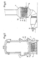
- La figure 1 est une vue en élévation de l'échangeur.
- La figure 2 est une coupe selon II-II de la figure 1 qui montre l'échangeur en vue de côté.
- La figure 3 est une vue de détail de la figure 1.
- La figure 4 est une vue de détail de la figure 2.
- La figure 5 représente l'application de l'échangeur selon l'invention à un appareil à lit fluidisé.
- La figure 6 représente l'application de l'échangeur selon l'invention à la récupération de la chaleur de fumées de combustion.
- L'échangeur représenté notamment par les figures 1 et 2 est placé dans un fluide à température élevée notamment dans un mélange solide-gaz du lit fluidisé d'un appareil à lit fluidisé ou encore dans un courant de gaz chaud ou de fumées chaudes provenant par exemple d'un four ou d'une chambre de combustion de turbine à gaz. Le fluide (mélange solide-gaz, gaz ou fumées) est contenu dans une enceinte 1 ou canalisé dans un conduit calorifugé 1. Le courant de gaz ou de fumées s'écoule verticalement de manière ascendante selon la flèche 11.
- Le mode de réalisation représenté comporte . deux faisceaux de tubes référencés 6 et 7 respectivement.
- Chaque faisceau comporte une paire de collecteurs d'entrée 21, 22 qui reçoivent un gaz relativement froid et une paire de collecteurs de sortie 31 et 32 qui recueillent le gaz chaud après que celui- ci soit passé dans les tubes 41 à 48.
- Lés collecteurs 21, 22, 31, 32 traversent une paroi de l'enceinte ou du conduit et s'étendent horizontalement, sensiblement jusqu'à la paroi opposée. Les collecteurs d'entrée 21 et 22 sont sensiblement situés à la même hauteur l'un par rapport à l'autre. De même les collecteurs de sortie 31 et 32 sont sensiblement situés à la même hauteur l'un par rapport à l'autre. Les collecteurs de sortie 31 et 32 sont situés au-dessus des collecteurs d'entrée 21 et 22 (c'est-à-dire en aval par rapport au sens d'écoulement 11 du gaz chaud). L'écartement entre les collecteurs de sortie 31 et 32 est sensiblement égal à l'écartement entre les collecteurs d'entrée 21 et 22.
- Les collecteurs d'entrée 21 et 22 sont supportés à leurs extrémités par l'enceinte ou le conduit 1. Ils supportent, par l'intermédiaire d'entretoises 51 et 52, les collecteurs de sortie 32 et 31 respectivement, l'ensemble du faisceau étant suspendu. Les collecteurs d'entrée 21 et 22 pour le gaz froid constituent la charpente de support de l'ensemble des faisceaux.
- Chaque faisceau se compose d'une pluralité de panneaux tubulaires 4 s'étendant verticalement les uns à côté des autres et qui sont constitués de tubes 41 à 48 s'étendant sous deux collecteurs d'entrée 21 et 22 et deux collecteurs de sortie 31 et 32. Ces tubes sont branchés en amont à la paire de collecteurs d'entrée 21 et 22 et en aval à la paire de collecteurs de sortie 31 et 32. Chaque panneau 4 se compose de deux demi-panneaux imbriqués l'un dans l'autre et raccordés chacun à un collecteur d'entrée 21 ou 22 et à un collecteur de sortie 31 ou 32.
- Chaque demi-panneau comporte un tube sous-collecteur d'entrée 41 ou 42 branché sous le collecteur d'entrée 21 ou 22 respectivement et qui se ramifie par des tubes contournés en lacets 43, 44, 45 ou 46, 47, 48 respectivement, ces tubes en lacets débouchant dans le collecteur de sortie 31 ou 32 qui est associé au collecteur d'entrée. Un collecteur de sortie tel que 31 associé au collecteur d'entrée 21 dans un demi-panneau se situe au-dessus du collecteur d'entrée 22 de l'autre demi-panneau. Les tubes en lacets 43 à 45 ou 46 à 48 sont branchés à la partie inférieure d'un tube sous-collecteur 41 ou 42 qui s'étend verticalement sous le collecteur d'entrée auquel il est branché. Les tubes en lacets 43 à'48 sont contournés de manière que leurs axes fassent des « hélices aplaties centrées sur un axe constituant l'axe vertical de symétrie des deux tubes sous-collecteurs 41 et 42. Ces deux tubes sous-collecteurs 41 et 42 sont situés à l'intérieur du cylindre fictif enveloppant les tubes en lacets 43 à 48 qui entourent donc lesdits tubes sous-collecteurs. Les tubes en lacets tels que 43 à 45 partant d'un tube sous-collecteur 41 s'enroulent dans l'intervalle s'étendant entre les spires des tubes en lacets 46 à 48 partant du second tube sous collecteur 42 de manière que ces tubes soient imbriqués les uns dans les autres, le sens d'enroulement des tubes 43 à 45 étant le même que celui des tubes 46 à 48. Ces tubes en lacets 43 à 48 sont envoûtés de manière à présenter des parties rectilignes raccordées par des coudes. Ils forment de chaque côté des tubes sous-collecteurs 41 et 42 une série de tronçons rectilignes. Ils sont enroulés avec un pas tel qu'il y ait un intervalle entre chaque tube et le tube voisin. Chaque tube en lacet 43 à 48 est, dans un coude, au contact de deux génératrices opposées d'un tube sous-collecteur. Dans chaque coude, l'intrados du tube est séparé du tube sous-collecteur voisin de manière à permettre les dilatations.
- Chaque tube sous-collecteur 41 ou 42 présente, le long d'une génératrice, une série de supports en porte-à-faux 411 et 421 respectivement. Ces supports en porte-à-faux sont fixés à intervalles réguliers le long d'une génératrice de chaque tube sous-collecteur. Les tubes en lacet 43 à 48 s'appuient sur ces supports en porte-à-faux 411 et 421. Chaque spire d'un tube en lacet est supportée par deux supports 411 et 421 fixés aux deux tubes sous collecteurs. Les supports 411 et 421 sont disposés dans chacun des intervalles compris entre deux tubes en lacets. Ces supports sont réalisés en métal et sont soudés aux tubes sous collecteurs. En variante ces supports pourraient être constitués par des anneaux en céramique ceinturant les tubes sous-collecteurs.
- Le fonctionnement est le suivant :
- L'enceinte ou le conduit 1 contient ou canalise un fluide très chaud (mélange solide-gaz de lit fluidisé ou gaz ou fumées).
- L'échangeur est utilisé pour réchauffer un gaz relativement froid qui est amené aux collecteurs d'entrée 21 et 22.
- Le gaz froid à réchauffer descend dans les tubes sous collecteurs 41 et 42 puis circule dans les tubes en lacets 43 à 48 avant d'être recueilli dans les collecteurs de sortie 31 et 32. Pendant ce parcours, le gaz circulant dans les tubes récupère la chaleur du lit fluidisé ou du gaz chaud à l'extérieur des tubes.
- Dans l'application de la figure 5, l'échangeur est placé au sein du lit 8 d'une chaudière à lit fluidisé. Cet échangeur constitue un réchauffeur d'air et il est plaçé en amont du faisceau de production de vapeur. Par exemple l'air qui entre dans l'échangeur vient d'un compresseur et l'air chaud qui sort est envoyé à une turbine à gaz.
- Dans l'application de la figure 6, l'échangeur est placé dans un conduit 1 qui canalise les fumées à très haute température provenant d'une turbine à gaz 9. L'air qui entre dans l'échangeur vient du compresseur de la turbine et l'air chaud qui sort est envoyé à la chambre de combustion de la turbine.
Claims (6)
Priority Applications (1)
| Application Number | Priority Date | Filing Date | Title |
|---|---|---|---|
| AT85400151T ATE30353T1 (de) | 1984-02-03 | 1985-01-30 | Roehrenwaermetauscher. |
Applications Claiming Priority (2)
| Application Number | Priority Date | Filing Date | Title |
|---|---|---|---|
| FR8401666A FR2559248B1 (fr) | 1984-02-03 | 1984-02-03 | Echangeur de chaleur a tubes |
| FR8401666 | 1984-02-03 |
Publications (2)
| Publication Number | Publication Date |
|---|---|
| EP0153214A1 EP0153214A1 (fr) | 1985-08-28 |
| EP0153214B1 true EP0153214B1 (fr) | 1987-10-21 |
Family
ID=9300734
Family Applications (1)
| Application Number | Title | Priority Date | Filing Date |
|---|---|---|---|
| EP85400151A Expired EP0153214B1 (fr) | 1984-02-03 | 1985-01-30 | Echangeur de chaleur à tubes |
Country Status (12)
| Country | Link |
|---|---|
| US (1) | US4553502A (fr) |
| EP (1) | EP0153214B1 (fr) |
| JP (1) | JPS60248995A (fr) |
| AT (1) | ATE30353T1 (fr) |
| AU (1) | AU584317B2 (fr) |
| BR (1) | BR8500468A (fr) |
| CA (1) | CA1239842A (fr) |
| DE (1) | DE3560800D1 (fr) |
| ES (1) | ES284317Y (fr) |
| FR (1) | FR2559248B1 (fr) |
| IN (1) | IN163788B (fr) |
| ZA (1) | ZA85791B (fr) |
Families Citing this family (15)
| Publication number | Priority date | Publication date | Assignee | Title |
|---|---|---|---|---|
| CA1331985C (fr) * | 1986-12-31 | 1994-09-13 | Richard C. Price | Echangeur de chaleur gaz-liquide, haute pression |
| US4776169A (en) * | 1988-02-03 | 1988-10-11 | Coles Jr Otis C | Geothermal energy recovery apparatus |
| US4994591A (en) * | 1989-06-02 | 1991-02-19 | The Research Foundation Of State University Of Ny | Platinum complexes derived from b-silyamines |
| US5005529A (en) * | 1990-04-23 | 1991-04-09 | Foster Wheeler Energy Corporation | Modular heat recovery steam generator having parallel offset headers |
| FR2705142B1 (fr) * | 1993-05-10 | 1995-10-27 | Inst Francais Du Petrole | Procede de regulation du niveau thermique d'un solide dans un echangeur de chaleur presentant des nappes cylindriques de tubes. |
| FR2752926B1 (fr) * | 1996-09-05 | 1998-10-09 | Gec Alsthom Stein Ind | Echangeur de chaleur d'encombrement reduit |
| FR2761147B1 (fr) * | 1997-03-24 | 1999-05-14 | Gec Alsthom Stein Ind | Echangeur de chaleur a encombrement reduit |
| FR2767380B1 (fr) * | 1997-08-18 | 1999-09-24 | Gec Alsthom Stein Ind | Dispositif d'echange thermique pour une chaudiere a lit fluidise circulant |
| DE19849709C2 (de) * | 1998-10-28 | 2000-09-14 | Krupp Uhde Gmbh | Verfahren und Wirbelschicht-Reaktor zur Oxichlorierung von Ethylen, Sauerstoff und HCl |
| US6237545B1 (en) * | 2000-04-07 | 2001-05-29 | Kellogg Brown & Root, Inc. | Refinery process furnace |
| CN1544873A (zh) * | 2003-11-21 | 2004-11-10 | 山东大学 | U型管-悬臂组合盘管复合流程换热器 |
| CN104006662B (zh) * | 2014-05-15 | 2015-10-07 | 中南大学 | 一种氧化铝焙烧炉流化床冷却器强化传热冷却单元 |
| CN107504505B (zh) * | 2017-08-28 | 2024-03-22 | 镇江裕太防爆电加热器有限公司 | 一种节能型循环利用尾气处理设备 |
| CN108826324A (zh) * | 2018-06-28 | 2018-11-16 | 无锡兴惠汽车配件制造有限公司 | 废气处理热力利用系统 |
| CN115790229B (zh) * | 2023-02-13 | 2023-05-09 | 成都天保节能环保工程有限公司 | 一种适用于流化床蓄热的结构的蓄热方法 |
Family Cites Families (14)
| Publication number | Priority date | Publication date | Assignee | Title |
|---|---|---|---|---|
| US1109041A (en) * | 1911-10-26 | 1914-09-01 | Albert A Cary | Steam-generator. |
| US1083199A (en) * | 1912-08-19 | 1913-12-30 | Ets Delaunay Belleville Sa | Water-tube boiler. |
| US1345231A (en) * | 1920-02-13 | 1920-06-29 | Dickinson S Cummings | Steam-boiler |
| US1780529A (en) * | 1927-11-14 | 1930-11-04 | Lloyd S Lanterman | Steam or vapor generator |
| GB356328A (en) * | 1930-06-16 | 1931-09-10 | John Riekie | Improvements in steam generators |
| GB661628A (en) * | 1949-06-28 | 1951-11-21 | La Mont Int Ass Ltd | Improvements in or relating to forced circulation steam boilers heated by waste gases |
| GB745231A (en) * | 1953-05-14 | 1956-02-22 | Howard William Barrett Webb | Improvements in water heaters and steam generators |
| FR1222175A (fr) * | 1958-05-06 | 1960-06-08 | Schmidt Sche Heissdampf | Chaudière à tubes d'eau comprenant des surfaces de chauffe par rayonnement |
| NL246772A (fr) * | 1959-01-02 | |||
| US3672847A (en) * | 1970-03-05 | 1972-06-27 | Selas Corp Of America | Reformer furnace |
| US4096909A (en) * | 1976-12-23 | 1978-06-27 | Dorr-Oliver Incorporated | Fluidized bed process heater |
| FR2405452A1 (fr) * | 1977-10-05 | 1979-05-04 | Stainless Equipment Cy | Echangeur de chaleur comportant un lit de materiau a mailles en contact avec un serpentin creux, et son procede de fabrication |
| FR2473697A1 (fr) * | 1980-01-11 | 1981-07-17 | Stein Industrie | Dispositif d'accrochage d'un panneau de tubes d'echange de chaleur |
| US4316435A (en) * | 1980-02-27 | 1982-02-23 | General Electric Company | Boiler tube silencer |
-
1984
- 1984-02-03 FR FR8401666A patent/FR2559248B1/fr not_active Expired
-
1985
- 1985-01-30 IN IN84/MAS/85A patent/IN163788B/en unknown
- 1985-01-30 DE DE8585400151T patent/DE3560800D1/de not_active Expired
- 1985-01-30 EP EP85400151A patent/EP0153214B1/fr not_active Expired
- 1985-01-30 AT AT85400151T patent/ATE30353T1/de not_active IP Right Cessation
- 1985-01-31 AU AU38223/85A patent/AU584317B2/en not_active Ceased
- 1985-02-01 ES ES1985284317U patent/ES284317Y/es not_active Expired
- 1985-02-01 BR BR8500468A patent/BR8500468A/pt unknown
- 1985-02-01 ZA ZA85791A patent/ZA85791B/xx unknown
- 1985-02-01 CA CA000473405A patent/CA1239842A/fr not_active Expired
- 1985-02-04 JP JP60019823A patent/JPS60248995A/ja active Pending
- 1985-02-04 US US06/697,678 patent/US4553502A/en not_active Expired - Fee Related
Also Published As
| Publication number | Publication date |
|---|---|
| ZA85791B (en) | 1986-01-29 |
| CA1239842A (fr) | 1988-08-02 |
| US4553502A (en) | 1985-11-19 |
| ATE30353T1 (de) | 1987-11-15 |
| IN163788B (fr) | 1988-11-12 |
| EP0153214A1 (fr) | 1985-08-28 |
| ES284317U (es) | 1985-09-01 |
| FR2559248A1 (fr) | 1985-08-09 |
| AU584317B2 (en) | 1989-05-25 |
| AU3822385A (en) | 1985-08-08 |
| ES284317Y (es) | 1986-05-01 |
| DE3560800D1 (en) | 1987-11-26 |
| BR8500468A (pt) | 1985-09-17 |
| JPS60248995A (ja) | 1985-12-09 |
| FR2559248B1 (fr) | 1986-07-04 |
Similar Documents
| Publication | Publication Date | Title |
|---|---|---|
| EP0153214A1 (fr) | Echangeur de chaleur à tubes | |
| EP0912868B1 (fr) | Installation d'echange thermique entre au moins trois fluides | |
| FR2506320A1 (fr) | Dispositif de chauffage pour les batteries de fours de cokefaction a regeneration | |
| FR2955929A1 (fr) | Echangeur de chaleur a condensation pour plusieurs fluides et dispositif de production de fluides chauds comprenant un tel echangeur | |
| CN1083573A (zh) | 蒸汽锅炉 | |
| CH635922A5 (fr) | Echangeur de chaleur a enceinte en spirale et procedes pour sa fabrication. | |
| EP0246486B1 (fr) | Echangeur de rechauffage d'air sous pression en contrecourant de fumées circulant dans des faisceaux tubulaires | |
| EP0077729B1 (fr) | Dispositif d'échange de chaleur pour une installation de gazéification de charbon | |
| FR2501832A1 (fr) | Epurateur - echangeur thermique pour gaz de combustion | |
| EP0086162B1 (fr) | Echangeur thermique à faisceau tubulaire métallique pour hautes températures | |
| US4034717A (en) | Multi-section heat exchanger means | |
| CN1067730A (zh) | 利用烟气和热风为热源的加热重油的方法及装置 | |
| CN2171086Y (zh) | 一种新型热风炉 | |
| CN113108300A (zh) | 一种大型组装锅炉双层多对流受热装置及其工作方法 | |
| FR2476804A1 (fr) | Economiseur pour chaudiere de chauffage central a circulation d'eau | |
| CN207132574U (zh) | 一种带匀流盖的光炉管及具有其的加热炉 | |
| FR2521269A1 (fr) | Chaudiere equipee d'un echangeur a condensation et d'un bruleur a combustible liquide | |
| CH340517A (fr) | Appareil thermique | |
| RU2132030C1 (ru) | Теплообменник | |
| FR2471571A1 (fr) | Echangeur de chaleur du type a nappe de tubes d'eau longitudinaux disposes autour d'une chambre de combustion cylindrique | |
| RU33998U1 (ru) | Конвективная поверхность нагрева водогрейных котлов | |
| US1820286A (en) | Boiler | |
| JP2558311Y2 (ja) | 太陽熱集熱装置 | |
| EP0051036B1 (fr) | Echangeur thermique à surface pour la récupération de chaleur | |
| JP3300083B2 (ja) | 竪型ドラム付水管式蒸発罐 |
Legal Events
| Date | Code | Title | Description |
|---|---|---|---|
| PUAI | Public reference made under article 153(3) epc to a published international application that has entered the european phase |
Free format text: ORIGINAL CODE: 0009012 |
|
| AK | Designated contracting states |
Designated state(s): AT BE CH DE FR GB IT LI LU NL SE |
|
| 17P | Request for examination filed |
Effective date: 19850821 |
|
| 17Q | First examination report despatched |
Effective date: 19860422 |
|
| GRAA | (expected) grant |
Free format text: ORIGINAL CODE: 0009210 |
|
| AK | Designated contracting states |
Kind code of ref document: B1 Designated state(s): AT BE CH DE FR GB IT LI LU NL SE |
|
| REF | Corresponds to: |
Ref document number: 30353 Country of ref document: AT Date of ref document: 19871115 Kind code of ref document: T |
|
| ITF | It: translation for a ep patent filed | ||
| REF | Corresponds to: |
Ref document number: 3560800 Country of ref document: DE Date of ref document: 19871126 |
|
| GBT | Gb: translation of ep patent filed (gb section 77(6)(a)/1977) | ||
| PG25 | Lapsed in a contracting state [announced via postgrant information from national office to epo] |
Ref country code: LU Free format text: LAPSE BECAUSE OF NON-PAYMENT OF DUE FEES Effective date: 19880131 |
|
| PLBE | No opposition filed within time limit |
Free format text: ORIGINAL CODE: 0009261 |
|
| STAA | Information on the status of an ep patent application or granted ep patent |
Free format text: STATUS: NO OPPOSITION FILED WITHIN TIME LIMIT |
|
| 26N | No opposition filed | ||
| PGFP | Annual fee paid to national office [announced via postgrant information from national office to epo] |
Ref country code: AT Payment date: 19881221 Year of fee payment: 5 |
|
| PGFP | Annual fee paid to national office [announced via postgrant information from national office to epo] |
Ref country code: CH Payment date: 19881222 Year of fee payment: 5 |
|
| PGFP | Annual fee paid to national office [announced via postgrant information from national office to epo] |
Ref country code: SE Payment date: 19890119 Year of fee payment: 5 |
|
| PGFP | Annual fee paid to national office [announced via postgrant information from national office to epo] |
Ref country code: DE Payment date: 19890123 Year of fee payment: 5 |
|
| PGFP | Annual fee paid to national office [announced via postgrant information from national office to epo] |
Ref country code: FR Payment date: 19890127 Year of fee payment: 5 |
|
| ITTA | It: last paid annual fee | ||
| PGFP | Annual fee paid to national office [announced via postgrant information from national office to epo] |
Ref country code: NL Payment date: 19890131 Year of fee payment: 6 Ref country code: GB Payment date: 19890131 Year of fee payment: 5 |
|
| PGFP | Annual fee paid to national office [announced via postgrant information from national office to epo] |
Ref country code: BE Payment date: 19890213 Year of fee payment: 5 |
|
| PG25 | Lapsed in a contracting state [announced via postgrant information from national office to epo] |
Ref country code: GB Effective date: 19900130 Ref country code: AT Effective date: 19900130 |
|
| PG25 | Lapsed in a contracting state [announced via postgrant information from national office to epo] |
Ref country code: SE Effective date: 19900131 Ref country code: LI Effective date: 19900131 Ref country code: CH Effective date: 19900131 Ref country code: BE Effective date: 19900131 |
|
| BERE | Be: lapsed |
Owner name: INSTITUT FRANCAIS DU PETROLE Effective date: 19900131 Owner name: CHARBONNAGES DE FRANCE Effective date: 19900131 Owner name: FRAMATOME ET CIE. Effective date: 19900131 |
|
| PG25 | Lapsed in a contracting state [announced via postgrant information from national office to epo] |
Ref country code: NL Effective date: 19900801 |
|
| NLV4 | Nl: lapsed or anulled due to non-payment of the annual fee | ||
| GBPC | Gb: european patent ceased through non-payment of renewal fee | ||
| PG25 | Lapsed in a contracting state [announced via postgrant information from national office to epo] |
Ref country code: FR Effective date: 19900928 |
|
| REG | Reference to a national code |
Ref country code: CH Ref legal event code: PL |
|
| PG25 | Lapsed in a contracting state [announced via postgrant information from national office to epo] |
Ref country code: DE Effective date: 19901002 |
|
| REG | Reference to a national code |
Ref country code: FR Ref legal event code: ST |
|
| EUG | Se: european patent has lapsed |
Ref document number: 85400151.8 Effective date: 19901107 |