EP0153429A1 - Unités modulaires d'emmagasinage combinables et extractibles - Google Patents
Unités modulaires d'emmagasinage combinables et extractibles Download PDFInfo
- Publication number
- EP0153429A1 EP0153429A1 EP84102029A EP84102029A EP0153429A1 EP 0153429 A1 EP0153429 A1 EP 0153429A1 EP 84102029 A EP84102029 A EP 84102029A EP 84102029 A EP84102029 A EP 84102029A EP 0153429 A1 EP0153429 A1 EP 0153429A1
- Authority
- EP
- European Patent Office
- Prior art keywords
- connector
- panels
- connectors
- recess
- longitudinal
- Prior art date
- Legal status (The legal status is an assumption and is not a legal conclusion. Google has not performed a legal analysis and makes no representation as to the accuracy of the status listed.)
- Granted
Links
- 238000003860 storage Methods 0.000 title claims abstract description 77
- 230000000295 complement effect Effects 0.000 claims description 9
- 230000009977 dual effect Effects 0.000 claims description 6
- 125000006850 spacer group Chemical group 0.000 claims description 5
- 238000000034 method Methods 0.000 claims description 2
- 230000015572 biosynthetic process Effects 0.000 claims 1
- 238000001125 extrusion Methods 0.000 claims 1
- 238000010276 construction Methods 0.000 description 8
- 239000000463 material Substances 0.000 description 6
- 239000004033 plastic Substances 0.000 description 5
- 230000013011 mating Effects 0.000 description 3
- 239000002184 metal Substances 0.000 description 3
- 238000005192 partition Methods 0.000 description 3
- 239000000853 adhesive Substances 0.000 description 2
- 230000001070 adhesive effect Effects 0.000 description 2
- 230000008901 benefit Effects 0.000 description 2
- 230000008878 coupling Effects 0.000 description 2
- 238000010168 coupling process Methods 0.000 description 2
- 238000005859 coupling reaction Methods 0.000 description 2
- 239000007769 metal material Substances 0.000 description 2
- 238000012986 modification Methods 0.000 description 2
- 230000004048 modification Effects 0.000 description 2
- 238000003825 pressing Methods 0.000 description 2
- 238000004026 adhesive bonding Methods 0.000 description 1
- 230000007547 defect Effects 0.000 description 1
- 239000004744 fabric Substances 0.000 description 1
- 230000006872 improvement Effects 0.000 description 1
- 238000003754 machining Methods 0.000 description 1
- 230000008520 organization Effects 0.000 description 1
- 239000000123 paper Substances 0.000 description 1
- 239000002023 wood Substances 0.000 description 1
Images



Classifications
-
- F—MECHANICAL ENGINEERING; LIGHTING; HEATING; WEAPONS; BLASTING
- F16—ENGINEERING ELEMENTS AND UNITS; GENERAL MEASURES FOR PRODUCING AND MAINTAINING EFFECTIVE FUNCTIONING OF MACHINES OR INSTALLATIONS; THERMAL INSULATION IN GENERAL
- F16B—DEVICES FOR FASTENING OR SECURING CONSTRUCTIONAL ELEMENTS OR MACHINE PARTS TOGETHER, e.g. NAILS, BOLTS, CIRCLIPS, CLAMPS, CLIPS OR WEDGES; JOINTS OR JOINTING
- F16B5/00—Joining sheets or plates, e.g. panels, to one another or to strips or bars parallel to them
- F16B5/07—Joining sheets or plates, e.g. panels, to one another or to strips or bars parallel to them by means of multiple interengaging protrusions on the surfaces, e.g. hooks, coils
-
- A—HUMAN NECESSITIES
- A47—FURNITURE; DOMESTIC ARTICLES OR APPLIANCES; COFFEE MILLS; SPICE MILLS; SUCTION CLEANERS IN GENERAL
- A47B—TABLES; DESKS; OFFICE FURNITURE; CABINETS; DRAWERS; GENERAL DETAILS OF FURNITURE
- A47B47/00—Cabinets, racks or shelf units, characterised by features related to dismountability or building-up from elements
- A47B47/0025—Horizontal connecting members adapted to receive and retain the edges of several panel elements
- A47B47/0041—Bars
Definitions
- the invention relates to a modular storage unit of box-like shape formed of flat panels fastened along their longitudinal edges by a set of identical connectors each having a longitudinal rib and a longitudinal recess.
- the rib of one connector slideably interfits with the recess of another connector so that a plurality of units may be arranged in a self supporting stack and one or more units may be slideably.shifted or removed from the stack without disturbance to and without collapse of the remaining stacked units.
- each storage unit is a three dimensioned open frame formed by a set of four longitudinal, four vertical and four cross bars, each frame being capable of being closed to a box-like structure by addition of flat panels or boxes.
- the longitudinal bars are provided with a rib and a recess that enable adjacent units to be slideably interfitted, as well as additional notches for receiving and fastening the cross bars and the panels.
- the present invention is an improvement thereon which greatly simplifies the structure and greatly reduces the cost of fabricating the device.
- the connectors are also simplified in structure to comprise elongated angle members requiring less material and provided with a complementary rib and recess for interfitting, and with U-shaped seats for frictionally fastening the panels, each connector being structured to be inexpensively extruded in its essential and final shape and cross sectional size.
- U.S. Patent 3,836,218 issued on September 17, 1974, provides for utilizing elongated horizontal connectors to mate with cubical box units to hold the latter in stacked configurations.
- the patent connectors each comprise four T-shaped ribs arranged in a cross, and the box units have T-shaped grooves formed in each wall surface to slideably receive a connector rib.
- the patent connectors do not function to fasten the box panels together as in the present invention. Instead the box unit of the patent must be assembled and expensively machined with mating T-shaped grooves to receive the connectors.
- the present invention utilizes inexpensive flat panels, and the connectors not only fasten the panels perpendicular to one another but permit each unit to be slideably removed from a stack.
- U.S. Patent 3,491,896, issued on January 27, 1970, provides a rib and a recess at each of opposite sides of flat panels to mate with those of other panels to form box-like units held in stacked configuration.
- the patentee does not use separate connectors to fasten the panels together, nor are his units, after stacking, intended to be normally slideable with respect to one another.
- the patentee suggests use of separate bars with ribs and recesses, they are utilized to rigidify the structure and conceal the tenons and grooves at the edges of assembled panels.
- Piretti also utilizes flat, rigid panels having a coupling rib and groove formed at each of opposite sides, the coupling elements being provided in edges angled at 45° to the plane of the panel.
- U.S. Patent No. 4,243,279 discloses rectangular storage units having mating sliding configurations at their sides and at their top and bottom surfaces. The patentee does not use connectors for fastening panels together in box form. Upper and lower plates with complementary interfitting ribs and grooves are used by the patentee to hold a vertical stack of storage units and to connect them to an adjacent stack.
- U.S. Patent 3,999,818, issued December 28, 1976 also discloses an interlocking system of cartridges or boxes in which the interfitting ribs and recesses are molded in the walls of the boxes, no separate connectors being used to fasten the walls of the boxes together.
- U.S. Patent 4,045,104 utilizes connectors having U-shaped slots to fasten panels into a box shape, but there are no complementary ribs and recesses on the connectors for sliding interfit with an adjacent box.
- a similar disadvantage lies with the connectors disclosed by U.S. Patent 3,820,299, issued June 28, 1974.
- a further disadvantage of the dozen or so variations of connector design illustrated in the last-cited patent is that each connector has short inturned hook flanges, which require the machining, or otherwise forming, of mating grooves in the panels secured to the connectors.
- one embodiment forms a connector and a panel integrally as a one-piece member but the combined connector panel still functions not only to fasten the member perpendicularly to a second member but also to slideably link a storage unit comprising the said two members to another storage unit formed of similar members. None of the patents mentioned above disclose or teach this dual function.
- the present invention overcomes the defects and disadvantages of the patented art, as briefly described above, by providing a storage system in which the individual units are formed of panels fastened together in perpendicular relation by identical connectors, each having a complementary rib and recess, and which slideably interfit with similar connectors on adjacent units.
- a primary object of the invention is to provide a simple connector member having the dual function of first fastening a pair of panels together to form the sides of a storage unit, and second, slideably interfitting with a similar connector on an adjacent unit to form a stack or wall of modular units.
- Another important object of the invention is to provide a complementary rib and recess on the connector member which fasten the panels to form the storage unit walls and which rib and recess interfit to allow stacking of the units in a wall structure, the ribs and recesses of adjacent units slideably interfitting to enable drawer-like operation of the units and complete removal of some of the units without collapse of or disturbance to the remaining units of the wall structure.
- Still another important object of the invention is to provide a modular storage unit construction in which one or more panels can be utilized to partially or completely enclose a cubic space and form a storage unit, thus enabling variation of a stacked wall of units to include not only complete boxes, but open ended tubes, drawers, partitions and shelves, and enabling the wall to function as an attractive and decorative piece of furniture, room divider or storage partition.
- Yet another important object of the invention is to provide a modular storage construction requiring only two parts, panels and connectors, although other parts, such as handles, hinges and the like, may be added if desired.
- Yet another object of the invention is to provide a modular storage unit which may be readily assembled and disassembled, and that these operations may be performed without the use of tools.
- Another important object of the invention is to provide a modular storage construction, having the above desribed characteristics, which is inexpensive to produce and easy to assemble and use, the storage units being preferably formed of plastic, wood, metal or inexpensive fibreboard panels and the connectors being extruded inexpensively of plastic or metal material.
- Still another important object of the invention is to provide a modular storage construction, having the above described characteristics, in which a connector and a panel are integrated to form a one-piece structure.
- Figure 1 illustrates a storage or partition wall 10, exemplifying one preferred embodiment of the invention, formed of self-sustaining, slideably interfitted, tubular storage units 12.
- the construction of each unit 12 is best seen in Figure 3, while the construction of the unit connector elements 14 is best seen in Figure 2.
- Each modular storage unit 12 comprises four rectangular, rigid panels 16 fastened together in perpendicular relation by four connectors 14 to form a tubular receptacle having top, bottom and side walls, but open at the front and rear, 18 and 20, respectively.
- the four panels 16 may be identical in size and shape and thus interchangeable, and are preferably formed of an inexpensive, rigid material, such as plastic, hardboard or even fibreboard or cardboard, of reenforced internal construction, so as to retain the shape of the unit when articles or materials are stored therein. Other and more expensive materials, such as metal or wood, obviously may be used to form the panels.
- Each connector is an elongated angle bar having a vertical flange 22 and a horizontal flange 24 which intersect in the line 26 extending longitudinally of the bar for its full length, which desirably equals the lengths of the panels 16.
- the flange intersection line 26 is above the bottom edge of vertical flange 22.
- a second horizontal flange 2.8 extends from the bottom edge of vertical flange 22 in the same direction as horizontal flange 24 and is connected to the latter by a short wall 30, perpendicular to both and spaced inwardly from the outer edges of flanges 24, 28.
- a second vertical flange 34 extends upwardly from flange 24 and is connected to flange 22 by a short horizontal wall 36, spaced inwardly from the upper edges of flanges 22 and 34.
- wall 36 with the edges of flanges 22 and 34 form an upwardly directed, elongated slot 38, of U-shaped cross-section, which seats and frictionally or with adhesive holds another panel 16 vertically in relation to the first panel held in slot 28.
- Flanges 34 and 22 together with wall 36 constitute an arm which is vertically H-shaped in section.
- Each connector 14 further comprises a longitudinal rib 40, of T-shaped cross-section, extending outwardly of the angle connector member flange 22 at the level of flange 24 preferably for the full length of connector 14.
- An elongated slit 42 parallel to the bottom edge of flange 22 extends the length of flange 28 and, together with space 44, forms an elongated recess having a T-shape in cross-section, with slit 42 forming the stem of the T.
- the recess 42, 44 is sized slightly larger than the rib 40 so as to slideably receive the rib of another connector and thus interlock with the corner of another storage unit in forming a portion of the wall 10 of Figure 1. In this way the connectors provide both interlocking support of adjacent storage units in the wall 10 and fastening of walls of a unit, while permitting sliding movement for drawerlike access or even complete removal of one or more units from wall 10, without collapse or disturbance of the wall.
- the connectors 14 are preferably extruded lengths of inexpensive plastic or metal material which are cut to the desired length to fit the panels 16.
- the described connector 14 shown in solid lines interfits with a second and identical connector rotated 90° counter clockwise about the longitudinal line of flange intersection 26 as an axis, the second connector being shown in broken lines.
- the second connector is shown interfitted with a third connector rotated 90° further in the same direction and shown in broken lines, while the third connector interfits with a fourth, broken line, connector rotated 90° further.
- Figure 2 illustrates the interfitting arrangement of four connectors at the common intersection of four adjacent storage units in wall 10, as for example the corner labeled A in Figure 1.
- any one of four identical connectors 14 may be used at any one of the corners of unit 12 to hold the wall panels 16 in proper relation, it being merely necessary to rotate a connector about its longitudinal axis to orient the rib 40 outwardly of the unit, with the panel receiving recesses 28, 38 extending in the proper directions, as shown in Figure 3.
- a connector 14 when placed to form the upper right edge of unit 12, Figure 3, has rib 40 extending, to the right.
- An identical connector turned 90° counterclockwise and fastened to panels 16 at the upper left edge of the unit has the rib 40 extending upwardly.
- an identical connector turned an additional 90° and fastened at the bottom left edge of the unit has the rib 40 extending to the left.
- the fourth connector an additional 90° in the same direction enables it to be fastened to the unit panels with rib 40 extending downwardly.
- one rib 40 of each of four adjacent units 12 interfits with a recess 42, 44 of an adjacent unit in a stack or wall of units 10.
- the connectors can be utilized with the ribs 40 faced in different directions than illustrated in Figures 1 and 3. If, for example, it became important to have a flat bottom on the storage unit, two connectors (rotated 180° relative to one another about their own axes and with one connector reversed end for end) could be used at the bottom of the unit and their ribs would project outwardly to the left and right.
- Each storage unit is illustrated in Figures 1 and 3 as being a tubular box open at the front and rear.
- the four panels 16 press fitted into the four connectors 14 are rigid and maintain the tubular shape of the unit 12 so that files, file folders, books, bric-a-brac or other suitable objects may be placed within the unit for storage or display.
- the edges of the panels 16 may be glued or cemented in the slots 32, 38 of the connectors. Screws, rivets, snaps or other types of fasteners may be used and the panels 16 may be secured to the connector flanges other than in the slots 32, 38.
- the sizes, shapes and lengths of the panels and connectors may obviously be varied. Many other variations are also obviously possible.
- top panel 16 may be omitted so that the unit would become an open-top three-sided tray.
- Front and rear panels may be added by fastening, gluing, or the like, to the edges of the side and bottom panels, and the unit would be converted to an open top drawer.
- the storage units 12 may be factory assembled or fabricated and sold to individuals as kits for home assembly. In the latter instance, each storage unit kit would constitute merely four identical connectors and four panels.
- any number of units 12 may be assembled in the described manner and interfitted to form a storage wall or structure, such as shown in Figure 1.
- each unit When thus arranged, with the ribs 40 slideably engaged in the recesses 42, 44 of adjacent connectors, each unit may be slid forwardly or rearwardly in the manner of a drawer. Because of the interlocking of the ribs and recesses, any one, several or even all of the units in any vertical line can be completely removed to another location without toppling of the remaining units. This is an important advantage since it permits removal and return or replacement of storage units without the need for handling or rearranging the other remaining units.
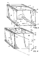
- the modified storage unit 12A shown in Figure 4 is in all respects identical with unit 12 of Figure 3 except that a rear wall 46 and a front wall 48 have been added.
- the rear wall 46 is fastened in any suitable manner, not shown, as by cementing to the rear edges of the side, top and bottom walls 16, to the rear edges of the connectors 14 or by screws, pins, snaps, clamps or other types of fasteners.
- Rigid closure panel 48, hinged as at 50 to the forward edge of the left side wall 16, is provided with a handle 52 and a latch, hook or lock (not shown) for retaining the door closure 48 in closed position as shown in solid lines in Figure 4. It will be noted that door 48 swings leftward to open as illustrated in broken lines.
- the unit need only be turned 90° clockwise so that hinges 50, 50 are at the top.
- the unit may be turned 90° clockwise in two further steps to allow the door to swing open toward the right and downwardly respectively, whichever is desired.
- the panels 16, 46 and 48 are made squares of equal size the unit may be slideably interfitted in a wall of identical units, such as 10, Figure 1, with the door 48 swinging to open in any one of the four directions as desired.
- a modified storage unit 12B is illustrated in Figures 5, 5A and 5B, and is identical with unit 12 except as will be explained.
- Four connectors 14 are again used, but only two side wall panels 16a and a bottom panel 16b are fastened to the connectors.
- Panels 16a and 16b are formed of less rigid, weaker or more flexible material than panels 16, for example, heavy paper, thin cardboard, reenforced cloth, etc. The weaker or more flexible panels are therefore unable to maintain the proper configuration of the unit 12B under all conditions of storage use or load.
- four rigid vertical spacer rods 54 are disposed adjacent the side panels 16a near their front and rear edges and serve to hold the upper and lower connectors suitably spaced apart.
- rods may be given right and left hand threads (as shown in Figures 5A and 5B) at their opposite ends, and are threaded into threaded openings 56, 56 in the flanges 24, 34 of the upper and lower connectors 14, respectively.
- four rigid, horizontal spacer rods 58 are disposed near the front and rear, upper and lower edges of the storage unit to hold the left and right connectors suitably spaced apart.
- Rods 58 are also oppositely threaded at their ends and screwed into the threaded openings 56 in flanges 24 and 34 of the appropriate right and left connectors.
- the rods 54 and 58 strengthen and rigidify the storage unit when weaker more flexible wall panels are to be used or are to be omitted entirely if desired.
- the rods 54, 58 may be fastened by threading into the connectors first and the panels 16a, 16b inserted later, or these steps may be reversed. If the storage unit 12B is formed as a cube, the eight rods are made identical.
- the modified storage unit 12C is similar to unit 12B, differing in the following respects.
- a single corrugated fibreboard strip, having top, bottom and side wall portions, 16b, defined by fold lines, is, at its corners, cemented or otherwise adhered to the inner surfaces of flanges 24, 34 of the connectors instead of being secured within the slots 32, 38.
- Openings 60, Figure 6A are provided at suitable locations near the edges of the panels 16b to seat and hold the unthreaded ends of rigid spacer rods 54a, 58a.
- Unit 12C is assembled and used, as well as disassembled, in a manner similar to that as explained above for unit 12B.
- Modified storage unit 12D illustrated in Figure 7 is similar to unit 12, Figure 3, but differs in the following respects. Only rigid side panels 16, 16 and four connectors 14 are utilized, as in unit 12A. The remaining surfaces are formed of a single strip of semi-rigid fibreboard 62 with three transverse fold lines 63, 65 and 67 dividing the strip into a bottom panel 64, a rear panel 66, a top panel 68 and a front panel 70. The crease or fold line 67 acts as a hinge to permit swinging open of the front panel 70 between unit opening and closing conditions.
- Storage unit 12D may be assembled and used in the same manner as explained for units 12 and 12A, except possibly that it is desirable to attach the four connectors by moving them transversely against the side edges of the strip wall portions 64 and 68 to fasten the edges in slots 32, 38. This may be done before or after the connectors have been fastened onto the two side panels 16.
- FIG 8 illustrates still another embodiment of the invention in which a connector and panel are integrated to fcrm a one-piece member.
- a connector and panel are integrated to fcrm a one-piece member.
- Such a member is generally referenced 80 and comprises a flat, hollow, rectangular plate having spaced, parallel face walls 82 and 84, preferably reenforced and rigidified by a plurality of angled, internal connecting walls 86, 88.
- the longitudinal recess 44 is formed, while the complementary rib 40 protrudes outwardly from wall 82 adjacent said edge. This rib and recess correspond to the T-shaped parts of connector 14, Figure 2.
- a longitudinal recess 90 is formed to extend along the panel adjacent the above named edge and this is complementary to and sized to slideably and frictionally receive a longitudinal rib 92 of another panel member to hold the latter perpendicular to the former.
- Rib 92 is formed along and to protrude from the edge opposite the edge of the panel member 80, which includes recess 44.
- Recess 90 and rib 92 are shown as having L-shaped cross sections.
- panel member 80 may be integrated from separate parts, it is preferred to extrude the complete panel longitudinally in the direction of arrow B, Figure 8, using a plastic or light weight metal as the material thereof.
- rib 92 of one panel may be slideably interfitted in recess 90 of another panel to hold the two perpendicular to one another, and four panels 80 may be assembled to form an open end tubular sleeve, such as illustrated at 12, Figure 3.
- This storage unit may be rigidified and rendered more permanent by cementing the ribs 92 in the recesses 90.
- a plurality of units so assembled may then be stacked by slideably interfitting the units by engagement of protruding ribs 40 in the recess 44 of adjacent units in the same manner as described for the storage units 12 and the other modifications previously described.
Landscapes
- Engineering & Computer Science (AREA)
- General Engineering & Computer Science (AREA)
- Mechanical Engineering (AREA)
- Assembled Shelves (AREA)
- Packaging Of Annular Or Rod-Shaped Articles, Wearing Apparel, Cassettes, Or The Like (AREA)
Priority Applications (4)
| Application Number | Priority Date | Filing Date | Title |
|---|---|---|---|
| US06/383,702 US4470647A (en) | 1982-06-01 | 1982-06-01 | Interfitting and removable modular storage units including connectors forming part of a unit as well as sliding support for adjacent units |
| DE8484102029T DE3482879D1 (de) | 1984-02-24 | 1984-02-24 | Zusammensetzbare und ausziehbare module fuer lager. |
| AT84102029T ATE55044T1 (de) | 1984-02-24 | 1984-02-24 | Zusammensetzbare und ausziehbare module fuer lager. |
| EP84102029A EP0153429B1 (fr) | 1982-06-01 | 1984-02-24 | Unités modulaires d'emmagasinage combinables et extractibles |
Applications Claiming Priority (2)
| Application Number | Priority Date | Filing Date | Title |
|---|---|---|---|
| US06/383,702 US4470647A (en) | 1982-06-01 | 1982-06-01 | Interfitting and removable modular storage units including connectors forming part of a unit as well as sliding support for adjacent units |
| EP84102029A EP0153429B1 (fr) | 1982-06-01 | 1984-02-24 | Unités modulaires d'emmagasinage combinables et extractibles |
Publications (2)
| Publication Number | Publication Date |
|---|---|
| EP0153429A1 true EP0153429A1 (fr) | 1985-09-04 |
| EP0153429B1 EP0153429B1 (fr) | 1990-08-01 |
Family
ID=26091489
Family Applications (1)
| Application Number | Title | Priority Date | Filing Date |
|---|---|---|---|
| EP84102029A Expired EP0153429B1 (fr) | 1982-06-01 | 1984-02-24 | Unités modulaires d'emmagasinage combinables et extractibles |
Country Status (2)
| Country | Link |
|---|---|
| US (1) | US4470647A (fr) |
| EP (1) | EP0153429B1 (fr) |
Families Citing this family (85)
| Publication number | Priority date | Publication date | Assignee | Title |
|---|---|---|---|---|
| US4470647A (en) * | 1982-06-01 | 1984-09-11 | Mark L. Bishoff | Interfitting and removable modular storage units including connectors forming part of a unit as well as sliding support for adjacent units |
| US4600252A (en) * | 1984-02-23 | 1986-07-15 | Barber Steven C | Modular metal cabinet |
| US4580841A (en) * | 1984-03-12 | 1986-04-08 | Steelcase, Inc. | Modular chair seat structure |
| USD305864S (en) | 1987-01-12 | 1990-02-06 | Jam Sun | Connector for folding crates |
| CA1327226C (fr) * | 1989-09-29 | 1994-02-22 | Lyle Enns | Meuble modulaire |
| USD329640S (en) | 1989-10-20 | 1992-09-22 | Ncr Corporation | Enclosure for electronic equipment |
| US5086593A (en) * | 1990-02-06 | 1992-02-11 | J. G. Furniture Systems Inc. | Modular built-in storage wall system |
| US5039177A (en) * | 1990-07-02 | 1991-08-13 | Haworth, Inc. | Cabinet with panel-attachment corner detail |
| DE4032426C2 (de) * | 1990-10-12 | 1999-04-08 | Lautenschlaeger Mepla Werke | Halterungsbeschlag für Schubladen-Ausziehführungen |
| USD342846S (en) | 1991-12-13 | 1994-01-04 | Mcneil-Ppc, Inc. | Sidekick display device |
| WO1994018869A1 (fr) * | 1993-02-18 | 1994-09-01 | John Stanley Reid | Dispositif de rangement modulaire et element associe |
| US5477594A (en) * | 1993-12-29 | 1995-12-26 | Christian Memorial Cultural Center | Niche panel |
| US5470139A (en) * | 1994-01-24 | 1995-11-28 | Hsiao; Szu-Chang | Combined display case |
| US5466057A (en) * | 1994-03-16 | 1995-11-14 | Blankenburg; Karl | Modular storage apparatus |
| US5916100A (en) * | 1997-12-12 | 1999-06-29 | ? Elward Systems Corporation | Method and apparatus for erecting wall panels |
| US6142321A (en) * | 1998-02-02 | 2000-11-07 | Westerlund Products Corporation | Adjustable shelving apparatus |
| US6079803A (en) * | 1998-02-02 | 2000-06-27 | Westerlund Products Corporation | Closet organization system and method for installing same |
| FR2797476A1 (fr) * | 1998-07-10 | 2001-02-16 | Yves Gijselbrecht | Profile de jonction multidirectionnel pour panneaux plats de toutes matieres |
| US6120116A (en) * | 1998-08-10 | 2000-09-19 | Buckeye Stamping Company, Inc. | Circuit board storage cabinet |
| USD444332S1 (en) | 2000-04-04 | 2001-07-03 | Westerlund Products Corporation | Slidable shelf |
| USD444974S1 (en) | 2000-05-30 | 2001-07-17 | Westerlund Products Corporation | Expandable shelf |
| USD445618S1 (en) | 2000-06-22 | 2001-07-31 | Westerlund Products Corporation | Expandable shelf |
| USD444655S1 (en) | 2000-06-22 | 2001-07-10 | Westerlund Products Corporation | Expandable shelf |
| USD444656S1 (en) | 2000-06-22 | 2001-07-10 | Westerlund Products Corporation | Expandable shelf |
| USD444975S1 (en) | 2000-06-22 | 2001-07-17 | Westerlund Products Corporation | Expandable shelf |
| USD455585S1 (en) | 2000-08-28 | 2002-04-16 | Westerlund Products Corporation | Expandable shelf |
| USD445620S1 (en) | 2000-09-15 | 2001-07-31 | Westerlund Products Corporation | Expandable shelf |
| US20040155562A1 (en) * | 2001-01-13 | 2004-08-12 | Darren Saravis | Snap together modular elements with straight connector |
| US20050104483A1 (en) * | 2001-01-13 | 2005-05-19 | Darren Saravis | Snap together connectable elements |
| US20050006991A1 (en) * | 2001-01-13 | 2005-01-13 | Darren Saravis | Snap together modular elements |
| US7472969B2 (en) * | 2001-01-13 | 2009-01-06 | Cube Concepts, Llc | Panel cover attachments to snap together connectors |
| US6557955B2 (en) * | 2001-01-13 | 2003-05-06 | Darren Saravis | Snap together modular storage |
| US20040145283A1 (en) * | 2001-01-13 | 2004-07-29 | Darren Saravis | Assembly method and device for snap together modular elements |
| US20040178704A1 (en) * | 2001-01-13 | 2004-09-16 | Darren Saravis | Snap and slide together connectors |
| US6988628B2 (en) * | 2002-09-25 | 2006-01-24 | Sauder Woodworking Company | Closet storage system |
| GB2409052B (en) * | 2003-12-12 | 2008-06-18 | Simon Richard Daniel | Cube shaped lamp and projection device for single slide |
| US8028453B2 (en) * | 2005-06-16 | 2011-10-04 | Hold That Thought, Inc. | Apparatus and methods for displaying a card |
| US7621421B2 (en) * | 2006-01-10 | 2009-11-24 | Abraham Ohayon | Variably configurable stackable bins |
| USD545592S1 (en) * | 2006-01-10 | 2007-07-03 | Abraham Ohayon | Stackable bin unit |
| US7410289B2 (en) * | 2006-03-21 | 2008-08-12 | Wolf Designs, Inc. | Interlockable watchwinder |
| USD555399S1 (en) * | 2006-08-02 | 2007-11-20 | Ritter Tsai | Storage cube |
| US7866769B2 (en) * | 2006-09-06 | 2011-01-11 | Target Brands, Inc. | Storage and organization system and components thereof |
| US7850258B2 (en) * | 2006-12-18 | 2010-12-14 | Caterpillar Inc | Inventory storage system |
| US9046212B2 (en) | 2007-02-08 | 2015-06-02 | 3Form, Llc | Panel mounting system |
| ITMC20070044A1 (it) | 2007-02-28 | 2008-09-01 | Compagnucci Holding Spa | Mobile pensile per cucine componibili. |
| US7922417B2 (en) * | 2007-05-25 | 2011-04-12 | Luis Alejandro Jimenez | Interlocking structural element for cabinets and enclosures |
| NL1034054C2 (nl) * | 2007-06-28 | 2008-12-30 | Aerocat B V | Trolley. |
| US8147009B1 (en) * | 2007-11-30 | 2012-04-03 | Rider H Joe | Cabinet component system |
| US20100259139A1 (en) * | 2009-03-16 | 2010-10-14 | Kevin Alan Tussy | Portable locker device |
| USD622959S1 (en) | 2009-03-17 | 2010-09-07 | Target Brands, Inc. | Storage unit |
| US8113600B2 (en) | 2009-03-17 | 2012-02-14 | Target Brands, Inc. | Storage and organization system with stackable shells |
| USD619832S1 (en) | 2009-03-17 | 2010-07-20 | Target Brands, Inc. | Drawer |
| CA2668598C (fr) * | 2009-06-11 | 2012-05-15 | Aluma Systems Inc. | Panneau de coffrage du beton |
| DE102009046689A1 (de) * | 2009-11-13 | 2011-05-19 | Peri Gmbh | Schalungselement |
| USD648939S1 (en) | 2010-02-24 | 2011-11-22 | Target Brands, Inc. | Bin |
| US20110241505A1 (en) * | 2010-03-31 | 2011-10-06 | Varoujan Tashjian | Modifiable modular furniture system with channel connector. |
| US7975990B1 (en) | 2010-05-25 | 2011-07-12 | Caldwell Tanks, Inc. | Misting array assembly having adjustable nozzles |
| US8870166B2 (en) | 2010-05-25 | 2014-10-28 | Caldwell Tanks, Inc. | Misting array assembly of an abatement system |
| US20120028534A1 (en) * | 2010-07-30 | 2012-02-02 | Dennis Clifford Unger | Structural support fastener |
| DE102011013159B4 (de) * | 2011-02-28 | 2013-02-07 | Rittal Gmbh & Co. Kg | Anbaurahmen für einen Schaltschrank oder ein Rack |
| CN102788065B (zh) * | 2011-05-18 | 2014-08-13 | 张文聪 | 组合架的连接件结构 |
| US20130015183A1 (en) * | 2011-07-14 | 2013-01-17 | David Fredette | Container system with interlock and collapsible capabilities |
| US20130106268A1 (en) * | 2011-10-26 | 2013-05-02 | Ming-Hwa Hsu | Structure of knockdown cabinet |
| USD661094S1 (en) | 2011-11-22 | 2012-06-05 | Target Brands, Inc. | Bin |
| USD682951S1 (en) | 2012-06-13 | 2013-05-21 | Target Brands, Inc. | Dollhouse unit |
| CN102748348A (zh) * | 2012-06-25 | 2012-10-24 | 成都绿迪科技有限公司 | 一种连接件型材 |
| SE538456C2 (sv) * | 2013-03-19 | 2016-07-12 | Nilsson Jeff | Positioneringsmedel och byggskiva för byggsats, samt byggsats |
| CN103405076B (zh) * | 2013-08-08 | 2015-07-08 | 杭州高脚马科技有限公司 | 拼接组装的展示体 |
| US9382038B2 (en) | 2014-04-04 | 2016-07-05 | Tyco Electronics Corporation | Modular enclosure |
| US9392708B2 (en) * | 2014-04-04 | 2016-07-12 | Tyco Electronics Corporation | Modular enclosure |
| USD738125S1 (en) | 2014-05-12 | 2015-09-08 | Steelcase Inc. | Foot rest |
| USD773558S1 (en) * | 2015-11-09 | 2016-12-06 | Deborah L. Melnick | Storage cube |
| USD792607S1 (en) | 2016-01-28 | 2017-07-18 | Oldcastle Building Products Canada Inc. | Connector block for a garden bed |
| USD792608S1 (en) | 2016-01-28 | 2017-07-18 | Oldcastle Building Products Canada Inc. | Connector block for a garden bed |
| US20170215345A1 (en) | 2016-01-28 | 2017-08-03 | Oldcastle Building Products Canada Inc. | Connector Block For Assembling a Garden Bed or a Planter Box |
| US10683645B2 (en) | 2017-03-23 | 2020-06-16 | Oatey Co. | Modular plumbing box system and methods of mounting the same |
| US10744419B2 (en) * | 2017-06-09 | 2020-08-18 | Qun Xia | Modular panel interlocking and reinforcing mechanism for building enclosures |
| US10548232B2 (en) | 2017-10-02 | 2020-01-28 | Te Connectivity Corporation | Modular enclosure and an assembly for constructing a modular enclosure |
| USD839011S1 (en) | 2017-12-13 | 2019-01-29 | Steelcase Inc. | Ottoman |
| US11116146B2 (en) * | 2019-07-29 | 2021-09-14 | T.U.I. Industrial Co., Ltd. | Cultivation assembly |
| CN111963526B (zh) * | 2020-06-15 | 2022-09-20 | 梅滕吴私人有限公司 | 一种组合式家具系统及一种组合式家具系统的墙板连接件 |
| US12025176B2 (en) | 2021-03-17 | 2024-07-02 | Steelcase Inc. | Clip fastener for privacy screen |
| JP2024539496A (ja) * | 2021-10-15 | 2024-10-28 | マキタ ユーエスエー インコーポレイテッド | 収納ボックスの連結性を備えたモジュール式収納システム、外部ボックス構成および付属品、ならびに、内部収納および蓋構成 |
| TWI827350B (zh) * | 2022-11-08 | 2023-12-21 | 台泥儲能科技股份有限公司 | 櫃體單元及櫃體系統 |
| US20260076480A1 (en) * | 2024-09-18 | 2026-03-19 | Taiwan Semiconductor Manufacturing Company, Ltd. | Filter installation bracket and cabinet apparatus using the same |
Citations (11)
| Publication number | Priority date | Publication date | Assignee | Title |
|---|---|---|---|---|
| FR1231465A (fr) * | 1959-07-29 | 1960-09-29 | Procédé et dispositif pour assembler des éléments quelconques, notamment des éléments de meubles | |
| US2962334A (en) * | 1958-07-08 | 1960-11-29 | Oxford Ltd | Filler strip for knock-down sectional furniture |
| FR1532502A (fr) * | 1967-05-29 | 1968-07-12 | Dispositif pour l'assemblage de parois de meubles ou de meubles entre eux | |
| GB1138734A (en) * | 1965-11-22 | 1969-01-01 | Meurop Sa | Process and extruded elements for industrial manufacturing of furniture, furniture components and their similar constructions |
| US3491896A (en) * | 1967-10-19 | 1970-01-27 | Thomas H Crary | Sectional structure |
| CH511342A (de) * | 1969-07-17 | 1971-08-15 | Paganini Titus | Verbindung von Bauplatten und Verfahren zur Herstellung derselben |
| US3722704A (en) * | 1970-07-23 | 1973-03-27 | Castelli Sas Anonima | Structural components for the composition of disassemblable pieces offurniture |
| US3836218A (en) * | 1972-11-24 | 1974-09-17 | A Hallal | Connecting device for modular constructions |
| FR2338409A1 (fr) * | 1976-01-15 | 1977-08-12 | Vinther Knud | Element connecteur pour constitution d'un ensemble |
| US4192562A (en) * | 1978-08-22 | 1980-03-11 | Bishoff Mark L | Interfitting and removable modular, frame, storage units |
| US4470647A (en) * | 1982-06-01 | 1984-09-11 | Mark L. Bishoff | Interfitting and removable modular storage units including connectors forming part of a unit as well as sliding support for adjacent units |
Family Cites Families (5)
| Publication number | Priority date | Publication date | Assignee | Title |
|---|---|---|---|---|
| GB594543A (en) * | 1944-12-05 | 1947-11-13 | James Mann New Hey Ltd | Improvements in box-like containers or furniture |
| US1071072A (en) * | 1909-07-08 | 1913-08-26 | Charles C Mengel | Knockdown box. |
| US1966875A (en) * | 1930-11-12 | 1934-07-17 | New England Box Company | Box |
| DE1140212B (de) * | 1959-05-30 | 1962-11-29 | Hans Klaembt | Zusammenlegbarer Kuehlgutbehaelter |
| DE1902716U (de) * | 1964-08-08 | 1964-10-22 | Manfred Malzacher | Plattenverbindungsglied. |
-
1982
- 1982-06-01 US US06/383,702 patent/US4470647A/en not_active Expired - Lifetime
-
1984
- 1984-02-24 EP EP84102029A patent/EP0153429B1/fr not_active Expired
Patent Citations (11)
| Publication number | Priority date | Publication date | Assignee | Title |
|---|---|---|---|---|
| US2962334A (en) * | 1958-07-08 | 1960-11-29 | Oxford Ltd | Filler strip for knock-down sectional furniture |
| FR1231465A (fr) * | 1959-07-29 | 1960-09-29 | Procédé et dispositif pour assembler des éléments quelconques, notamment des éléments de meubles | |
| GB1138734A (en) * | 1965-11-22 | 1969-01-01 | Meurop Sa | Process and extruded elements for industrial manufacturing of furniture, furniture components and their similar constructions |
| FR1532502A (fr) * | 1967-05-29 | 1968-07-12 | Dispositif pour l'assemblage de parois de meubles ou de meubles entre eux | |
| US3491896A (en) * | 1967-10-19 | 1970-01-27 | Thomas H Crary | Sectional structure |
| CH511342A (de) * | 1969-07-17 | 1971-08-15 | Paganini Titus | Verbindung von Bauplatten und Verfahren zur Herstellung derselben |
| US3722704A (en) * | 1970-07-23 | 1973-03-27 | Castelli Sas Anonima | Structural components for the composition of disassemblable pieces offurniture |
| US3836218A (en) * | 1972-11-24 | 1974-09-17 | A Hallal | Connecting device for modular constructions |
| FR2338409A1 (fr) * | 1976-01-15 | 1977-08-12 | Vinther Knud | Element connecteur pour constitution d'un ensemble |
| US4192562A (en) * | 1978-08-22 | 1980-03-11 | Bishoff Mark L | Interfitting and removable modular, frame, storage units |
| US4470647A (en) * | 1982-06-01 | 1984-09-11 | Mark L. Bishoff | Interfitting and removable modular storage units including connectors forming part of a unit as well as sliding support for adjacent units |
Also Published As
| Publication number | Publication date |
|---|---|
| US4470647A (en) | 1984-09-11 |
| EP0153429B1 (fr) | 1990-08-01 |
Similar Documents
| Publication | Publication Date | Title |
|---|---|---|
| US4470647A (en) | Interfitting and removable modular storage units including connectors forming part of a unit as well as sliding support for adjacent units | |
| US4171150A (en) | Mountable storage furniture | |
| US4712336A (en) | Interconnecting "full bleed" modular panel and connective hardware system to form a variety of exhibit and office interior enclosures | |
| US7568767B2 (en) | Snap-together patio bench | |
| US5466058A (en) | Stackable interlocking modular storage system | |
| US6174116B1 (en) | Adjustable interlocking panels | |
| US4887874A (en) | Knockdown drawers and bins | |
| US7866769B2 (en) | Storage and organization system and components thereof | |
| US5036778A (en) | Assemblable modular elements, in particular in thin sheet, for the formation of a metal shelving | |
| US4373449A (en) | Literature shelving | |
| US5605389A (en) | Cabinet, bookcase, locker and cubby structures | |
| US4285559A (en) | Combining drawers | |
| US4287837A (en) | Furniture assembly | |
| US20030222545A1 (en) | System of interlocking storage and display modules connectable in a plurality of different configurations | |
| US4408812A (en) | Dismountable furniture | |
| US20060250052A1 (en) | Modular furniture subassembly, component therefor and method of assembling a modular furniture subassembly | |
| US4986038A (en) | Component exhibit system | |
| US5562050A (en) | Collapsible article of furniture | |
| US5322167A (en) | File holder | |
| CA2270497A1 (fr) | Systeme de construction a partir de panneaux modulaires | |
| MXPA03006269A (es) | Almacen modular armable en el lugar. | |
| US4047777A (en) | Knockdown put-together article of furniture | |
| US4867319A (en) | Drawer organizer with removable sections and blank therefor | |
| US4437278A (en) | Wall partition locking system | |
| CA1257851A (fr) | Rayonnage modulaire |
Legal Events
| Date | Code | Title | Description |
|---|---|---|---|
| PUAI | Public reference made under article 153(3) epc to a published international application that has entered the european phase |
Free format text: ORIGINAL CODE: 0009012 |
|
| AK | Designated contracting states |
Designated state(s): AT BE CH DE FR GB IT LI LU NL SE |
|
| 17P | Request for examination filed |
Effective date: 19860228 |
|
| 17Q | First examination report despatched |
Effective date: 19870527 |
|
| GRAA | (expected) grant |
Free format text: ORIGINAL CODE: 0009210 |
|
| AK | Designated contracting states |
Kind code of ref document: B1 Designated state(s): AT BE CH DE FR GB IT LI LU NL SE |
|
| PG25 | Lapsed in a contracting state [announced via postgrant information from national office to epo] |
Ref country code: SE Free format text: THE PATENT HAS BEEN ANNULLED BY A DECISION OF A NATIONAL AUTHORITY Effective date: 19900801 Ref country code: NL Effective date: 19900801 Ref country code: IT Free format text: LAPSE BECAUSE OF FAILURE TO SUBMIT A TRANSLATION OF THE DESCRIPTION OR TO PAY THE FEE WITHIN THE PRESCRIBED TIME-LIMIT;WARNING: LAPSES OF ITALIAN PATENTS WITH EFFECTIVE DATE BEFORE 2007 MAY HAVE OCCURRED AT ANY TIME BEFORE 2007. THE CORRECT EFFECTIVE DATE MAY BE DIFFERENT FROM THE ONE RECORDED. Effective date: 19900801 Ref country code: FR Effective date: 19900801 Ref country code: BE Effective date: 19900801 Ref country code: AT Effective date: 19900801 |
|
| REF | Corresponds to: |
Ref document number: 55044 Country of ref document: AT Date of ref document: 19900815 Kind code of ref document: T |
|
| REF | Corresponds to: |
Ref document number: 3482879 Country of ref document: DE Date of ref document: 19900906 |
|
| EN | Fr: translation not filed | ||
| NLV1 | Nl: lapsed or annulled due to failure to fulfill the requirements of art. 29p and 29m of the patents act | ||
| PG25 | Lapsed in a contracting state [announced via postgrant information from national office to epo] |
Ref country code: GB Effective date: 19910224 |
|
| PG25 | Lapsed in a contracting state [announced via postgrant information from national office to epo] |
Ref country code: LU Free format text: LAPSE BECAUSE OF NON-PAYMENT OF DUE FEES Effective date: 19910228 Ref country code: LI Effective date: 19910228 Ref country code: CH Effective date: 19910228 |
|
| PGFP | Annual fee paid to national office [announced via postgrant information from national office to epo] |
Ref country code: DE Payment date: 19910430 Year of fee payment: 8 |
|
| PLBE | No opposition filed within time limit |
Free format text: ORIGINAL CODE: 0009261 |
|
| STAA | Information on the status of an ep patent application or granted ep patent |
Free format text: STATUS: NO OPPOSITION FILED WITHIN TIME LIMIT |
|
| 26N | No opposition filed | ||
| GBPC | Gb: european patent ceased through non-payment of renewal fee | ||
| REG | Reference to a national code |
Ref country code: CH Ref legal event code: PL |
|
| PG25 | Lapsed in a contracting state [announced via postgrant information from national office to epo] |
Ref country code: DE Effective date: 19921103 |