EP0153532A2 - Vorrichtung zum Aufbringen von Flüssigkeit in einem Walzwerk - Google Patents
Vorrichtung zum Aufbringen von Flüssigkeit in einem Walzwerk Download PDFInfo
- Publication number
- EP0153532A2 EP0153532A2 EP84308544A EP84308544A EP0153532A2 EP 0153532 A2 EP0153532 A2 EP 0153532A2 EP 84308544 A EP84308544 A EP 84308544A EP 84308544 A EP84308544 A EP 84308544A EP 0153532 A2 EP0153532 A2 EP 0153532A2
- Authority
- EP
- European Patent Office
- Prior art keywords
- valve
- diaphragm
- spray
- manifold
- bar
- Prior art date
- Legal status (The legal status is an assumption and is not a legal conclusion. Google has not performed a legal analysis and makes no representation as to the accuracy of the status listed.)
- Granted
Links
Images
Classifications
-
- B—PERFORMING OPERATIONS; TRANSPORTING
- B21—MECHANICAL METAL-WORKING WITHOUT ESSENTIALLY REMOVING MATERIAL; PUNCHING METAL
- B21B—ROLLING OF METAL
- B21B45/00—Devices for surface or other treatment of work, specially combined with or arranged in, or specially adapted for use in connection with, metal-rolling mills
- B21B45/02—Devices for surface or other treatment of work, specially combined with or arranged in, or specially adapted for use in connection with, metal-rolling mills for lubricating, cooling, or cleaning
- B21B45/0203—Cooling
- B21B45/0209—Cooling devices, e.g. using gaseous coolants
- B21B45/0215—Cooling devices, e.g. using gaseous coolants using liquid coolants, e.g. for sections, for tubes
- B21B45/0233—Spray nozzles, Nozzle headers; Spray systems
-
- B—PERFORMING OPERATIONS; TRANSPORTING
- B05—SPRAYING OR ATOMISING IN GENERAL; APPLYING FLUENT MATERIALS TO SURFACES, IN GENERAL
- B05B—SPRAYING APPARATUS; ATOMISING APPARATUS; NOZZLES
- B05B1/00—Nozzles, spray heads or other outlets, with or without auxiliary devices such as valves, heating means
- B05B1/30—Nozzles, spray heads or other outlets, with or without auxiliary devices such as valves, heating means designed to control volume of flow, e.g. with adjustable passages
- B05B1/3013—Lift valves
-
- B—PERFORMING OPERATIONS; TRANSPORTING
- B21—MECHANICAL METAL-WORKING WITHOUT ESSENTIALLY REMOVING MATERIAL; PUNCHING METAL
- B21B—ROLLING OF METAL
- B21B27/00—Rolls, roll alloys or roll fabrication; Lubricating, cooling or heating rolls while in use
- B21B27/06—Lubricating, cooling or heating rolls
- B21B27/10—Lubricating, cooling or heating rolls externally
Definitions
- This invention relates to means for applying liquid, e.g. coolant or lubricant, and in particular, although not exclusively to a spray unit for a rolling mill for supplying lubricating and/or cooling fluid to the mill rolls or to material being rolled therein.
- liquid e.g. coolant or lubricant
- a spray unit for a rolling mill includes a spray bar, to be mounted adjacent the mill rolls, having a manifold for liquid to be sprayed and series of spray nozzles or sets of spray nozzles spaced along the spray bar.
- Each nozzle or set of nozzles communicates with the manifold via a conduit, and a diaphragm of a diaphragm type valve is arranged to close the end of the conduit projecting into the manifold and thereby regulate the supply of liquid, under the control of diaphragm control means.
- One type of diaphragm control means described in the application uses pressurised air to force the diaphragm into an obturation position.
- a compartment is provided adjacent each diaphragm-valve with the diaphragm defining one wall of the compartment, and the pressurised air is provided to each of the compartments to move the diaphragm to close off the end of the respective conduit.
- the other type of diaphragm control means described is a solenoid which is arranged so that a moveable core can engage the diaphragm to move the diaphragm to the obturation position.
- the present invention seeks to provide a spray unit for a rolling mill, which overcomes disadvantages of the described spray unit.
- the present invention seeks to provide an improved apparatus for applying liquid for a rolling mill.
- the invention provides an apparatus for applying liquid for cooling and/or lubricating a rolling mill having mill rolls, comprising: a bar for mounting adjacent the mill rolls, a manifold in the bar for liquid to be sprayed; a series of valve units carried by, and spaced along the bar; for each valve unit, a liquid delivery conduit communicating with the manifold, for each valve unit a flexible diaphragm moveable to close with one side the respective conduit, a source of control fluid under pressure; for each diaphragm, a solenoid operated fluid valve arranged to control the flow of the control fluid between the source of the fluid under pressure and the other side of the diaphragm whereby the diaphragm will be moved to close the conduit; a second manifold in the bar, for the supply of control fluid under pressure, and the solenoid operated valve being arranged to control the flow of fluid between the second manifold and the space on the said other side of the diaphragm.
- the apparatus for applying liquid of the invention may be used with various applicator means which would be mounted on the bar or each valve unit, and be operatively connected to the liquid delivery conduit of a respective valve unit.
- the applicator means are spray nozzles as described hereinafter and the apparatus for applying liquid can then be termed a spray unit.
- the invention provides a spray unit for a rolling mill, comprising: a spray bar which is adapted to be mounted adjacent the mill rolls and which has a manifold for liquid to be sprayed; a series of spray nozzles or sets of spray nozzles carried by, and spaced along the bar and each nozzle or set being connected to a conduit communicating with the manifold; for each nozzle or set of nozzles a flexible diaphragm moveable to close with one side the conduit, and for each diaphragm a solenoid operated fluid valve;and the spray bar having a second manifold for a supply of fluid under pressure; and the solenoid operated valve being arranged to control the flow of a fluid between the second manifold, and a space on the other side of the diaphragm, whereby the diaphragm will be moved to close the conduit.
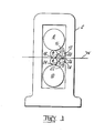
- a rolling mill 2 has two roll assemblies, exemplified by work roll 4 and back-up roll 8, and work roll 6 and back-up roll 10.
- a workpiece W is shown as being rolled between the two assemblies.
- the mill is provided with spray bars 12, 14 arranged adjacent the mill and parallel to the roll axes.
- the spray bar 12 has spaced along its length sets of nozzles, each set comprising a jet nozzle 16 for directing fluid to the top back-up roll, a nozzle 18 for directing fluid to the top work roll and a nozzle 20 for directing fluid to the upper side of the workpiece.
- Spray bar 14 is similar, having nozzles 22, 24 and 26 for directing fluid to the bottom back-up roll, the bottom work roll and the underside of the workpiece respectively.
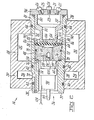
- Spray bar 14 has parallel first and second manifolds 28 and 30_with_ chambers 32 and 3-4 extending the entire length of the spray bar.
- Manifold 28 is supplied with liquid coolant (water or a water/oil emulsion) while manifold 30 is supplied with air under pressure.
- the spray bar has aligned bores 38 which open to the chambers 32 and 34.
- a valve unit 36 which includes an external sleeve 37, is receivable in the bores 38 and crosses the chambers 32 and 34.
- Sleeve 37 has a flange 41 at one end to locate the valve unit axially with respect to the spray bar.
- the valve unit 36 has a valve block 48, a valve body 52 and a diaphragm 50 anchored peripherally between valve block 48 and the valve body 52 which together fit within sleeve 37.
- the valve block 48 is generally cylindrical with an annular recess 54 adjacent one end face 62, which is connected by a radial bore 58 to an axial, blind hole 56 in that end face 62.
- a shallow conical depression 68 in the other end face 64 is connected by an axially parallel bore 66 to the first end face 62.
- the block 48 fits within the sleeve 37 with the first end face 62 abutting an internal shoulder 70 of the sleeve 37.
- the sleeve 37 has a short radial hole 72 which communicates with the chamber 34 of second manifold 30, and an axially parallel bore 74 in the sleeve 37 connects the radial hole 72 to the surface of the shoulder 70, adjacent the annular recess 54 in the valve block 48.
- the chamber 34 communicates with the annular recess 54 in the valve block 48 and thereby with the axial blind hole 56.
- the valve block 48 has an annular seal 76 in the end face 62, which engages the shoulder 70 of the sleeve, and an annular seal 78 which engages with the main internal wall of the sleeve 37.
- the valve body 52 is generally cylindrical with a main portion 80 of external diameter substantially equal to the internal diameter of the sleeve 37, and an extension 82 of reduced diameter.
- the end of the cylindrical extension 82 is closed and has through holes 84.
- An annular flange 86 projects radially from the end of cylindrical extension 82, and has through holes 88.
- the flange 86 has shallow conical form and slopes away from the remainder of the valve body 52 to abut the diaphragm 50, thereby providing a shallow valve cavity 106 between the diaphragm 50 and the closed end of -the cylindrical extension 82.
- the region about the cylindrical extension 82 between the flange 86 and the main cylinder 80 of the valve body forms an annular cavity 92.
- a series of radial through holes 90 in the sleeve 37 communicate the chamber 32 of manifold 28 with the annular cavity 92 about the extension 82.
- the diaphragm 58 is peripherally held securely between the valve block 48 and valve body 52.
- the diaphragm 58 is a close fit within sleeve 37 thereby providing a liquid tight seal between the valve block and the valve body.
- the diaphragm 58 closes the depression 68 in the end face of the valve block 48, except for the bore 66, to define a diaphragm chamber 102.
- the valve block 48 and body 52 are held in place by an end cap 94 in which are secured the set of spray nozzles 22, 24, 26.
- the spray nozzles 22, 24, 26 communicates with the inside of valve body 52 via conduits 21, 23 and 25 respectively.
- a solenoid operated air valve 98 of known construction e.g. Clippard type evo-3m is mounted on the valve block 48 by a threaded, bored spigot 100 which is a screw fit in the blind hole 56.
- the solenoid valve is fitted so that an outlet port of the valve coincides with opening of the bore 66 to the diaphragm chamber 102, and a vent in the valve is connected via a pipe 99 to the atmosphere.
- the solenoid valve is connected to an electrical supply by control leads 104.
- valve 46 operates as follows.
- Manifold 28 is connected to a supply of coolant/lubricant and manifold 30 to a supply of pressurised air.
- Air under pressure in manifold 30 passes from cavity 34 through the radial hole 72, and the bore 74 into the annular recess 54 of the valve block 48 and thence, via bore 58 and blind hole 56 to hollow spigot 100 and the input side of solenoid valve 98.
- the solenoid valve 98 controls the flow of the air under pressure to diaphragm chamber 102 via bore 66.
- coolant/lubricant in the manifold 28 passes from chamber 32, through radial holes 90 into the annular cavity 92j, through the holes 88 in the annular flange 86. into the valve cavity 106 into the valve body 52 through holes 84 and out through the spray nozzles.
- the solenoid valve When the solenoid valve is operated to supply air to the diaphragm chamber 102 the pressure of air flexes the diaphragm 50 into engagement with the end of the valve body 52 thereby closing the holes 84 in the end of the valve body and the holes 88 in the annular flange 86, and cutting off the supply of coolant/lubricant fluid to the spray nozzles.
- the diaphragm 50 need not close both the holes 84 in the valve body and the holes 88 in the annular flange 86, but closure of both sets of holes is preferable.
- valve unit 36 has only two moving parts - the solenoid air valve 98 and the diaphragm 50 - which makes the unit durable and reliable. Furthermore, if servicing is required, indentification of a potential fault is made relatively simply and servicing is facilitated by the whole valve unit 36 being removable from one side of the spray bar, after control leads 104 have been disconnected. Similarly replacement of a valve unit can be effected from one side of the spray bar, and by provision of similar spare valve units, the "down time" of the spray unit can be reduced, while a particular valve unit is being serviced.
- a particular advantage of the spray unit of the preferred embodiment is the absence of a multiplicity of air lines which were present in previous spray units where each valve had a separate air line.
- the valve unit described has a separate set of control leads 104, but a single set of control leads may be provided with each solenoid air valve being adapted 'to respond to a particular control signal. Alternatively, a group of valve units may be adapted to respond to a particular control signal. Such an arrangement may be computer controlled to take advantage of the use of the electrically operated solenoid valves.
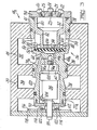
- FIG. 3 An alternative embodiment is shown in Figure 3 where, apart from the features referred to below, the spray bar and operative components are identical to those shown in Figure 2, and similar reference numerals have been used for like parts.
- a valve block 48A is formed in one with a sieeve 37A.
- the sleeve 37A is formed with an annular groove 120 which communicates via bores 74A and 58A with a blind hole 56A and spigot 100.
- a bore 66A connects the diaphragm chamber 102 with the solenoid valve 98.
- a cover plate 110 fixed by screws 112 to the end face of the sleeve 37A, carries spring contacts 114 to which the control leads 104 are connected.
- a printed circuit board 116 is carried by a cover plate 118 which is attached to the spray bar 14A.
- the printed circuit board 116 carries a circuit with metal control lines 122 for connection to the solenoid 98.
- the contacts 114 engage with the appropriate metal control lines 122 of the circuit.
Landscapes
- Engineering & Computer Science (AREA)
- Mechanical Engineering (AREA)
- Nozzles (AREA)
- Metal Rolling (AREA)
Priority Applications (1)
| Application Number | Priority Date | Filing Date | Title |
|---|---|---|---|
| AT84308544T ATE35780T1 (de) | 1984-02-20 | 1984-12-07 | Vorrichtung zum aufbringen von fluessigkeit in einem walzwerk. |
Applications Claiming Priority (2)
| Application Number | Priority Date | Filing Date | Title |
|---|---|---|---|
| GB8404387 | 1984-02-20 | ||
| GB848404387A GB8404387D0 (en) | 1984-02-20 | 1984-02-20 | Applying liquid for rolling mill |
Publications (3)
| Publication Number | Publication Date |
|---|---|
| EP0153532A2 true EP0153532A2 (de) | 1985-09-04 |
| EP0153532A3 EP0153532A3 (en) | 1986-07-09 |
| EP0153532B1 EP0153532B1 (de) | 1988-07-20 |
Family
ID=10556873
Family Applications (1)
| Application Number | Title | Priority Date | Filing Date |
|---|---|---|---|
| EP84308544A Expired EP0153532B1 (de) | 1984-02-20 | 1984-12-07 | Vorrichtung zum Aufbringen von Flüssigkeit in einem Walzwerk |
Country Status (7)
| Country | Link |
|---|---|
| US (1) | US4638950A (de) |
| EP (1) | EP0153532B1 (de) |
| JP (1) | JPH0741302B2 (de) |
| AT (1) | ATE35780T1 (de) |
| CA (1) | CA1237298A (de) |
| DE (1) | DE3472761D1 (de) |
| GB (1) | GB8404387D0 (de) |
Cited By (5)
| Publication number | Priority date | Publication date | Assignee | Title |
|---|---|---|---|---|
| EP0205295A3 (en) * | 1985-06-10 | 1987-10-07 | Davy Mckee (Poole) Limited | Improvements relating to the lubrication of rolling mills |
| EP0205296A3 (en) * | 1985-06-10 | 1987-10-07 | Davy Mckee (Poole) Limited | Improvements relating to lubrication of rolling mills |
| FR2618869A1 (fr) * | 1987-07-27 | 1989-02-03 | Baun Daniel | Ensemble a soupapes a commande pilote pour fluide de refroidissement |
| EP3251762A1 (de) | 2016-06-02 | 2017-12-06 | Primetals Technologies Austria GmbH | Schmiervorrichtung zum aufbringen eines schmiermittels beim walzen eines walzgutes |
| CN108515081A (zh) * | 2018-03-30 | 2018-09-11 | 上海贺力液压机电有限公司 | 热轧机立辊辊身润滑装置 |
Families Citing this family (6)
| Publication number | Priority date | Publication date | Assignee | Title |
|---|---|---|---|---|
| US4738400A (en) * | 1987-02-11 | 1988-04-19 | Almo Manifold & Tool Co. | Spray bar assembly |
| US5829425A (en) * | 1996-02-16 | 1998-11-03 | Lincoln Brass Works, Inc. | Integral burner control and manifold |
| CN100396394C (zh) * | 2006-03-10 | 2008-06-25 | 叶林 | 开放式高效水冷却喷嘴 |
| CN103480652A (zh) * | 2013-09-25 | 2014-01-01 | 洛阳正扬冶金技术股份有限公司 | 双腔式气控液轧机喷射梁 |
| DE102013022223B4 (de) * | 2013-12-20 | 2025-10-16 | Raziol Zibulla & Sohn Gmbh | Verfahren zum Aufbringen von flüssigem bis pastösem Befettungsmittel auf eine Werkstückoberfläche |
| CN108687143A (zh) * | 2018-04-08 | 2018-10-23 | 新疆八钢铁股份有限公司 | 螺旋喷雾式型钢除尘器 |
Family Cites Families (10)
| Publication number | Priority date | Publication date | Assignee | Title |
|---|---|---|---|---|
| US3145967A (en) * | 1962-04-27 | 1964-08-25 | Lawrence H Gardner | Elastic sleeve valve |
| US3570725A (en) * | 1968-11-15 | 1971-03-16 | Nordson Corp | Applicator having a fixed module with static parts and a removable module with moving parts |
| GB1195178A (en) * | 1969-03-18 | 1970-06-17 | Hills Mccanna Co | Fluid Actuated Diaphragm Valve. |
| US3684177A (en) * | 1970-09-10 | 1972-08-15 | Transland Aircraft Inc | Spraying apparatus and control system therefor |
| FR2334427A1 (fr) * | 1975-12-09 | 1977-07-08 | Renault | Bloc multibuses de pulverisation de surfaces d'outillages |
| US4081141A (en) * | 1976-09-27 | 1978-03-28 | Almo Manifold And Tool Company | Spray bars for metal rolling and flow control valves |
| EP0041863B1 (de) * | 1980-06-11 | 1985-01-16 | DAVY McKEE (POOLE) LIMITED | Sprühvorrichtung für Walzwerk |
| US4387739A (en) * | 1981-09-22 | 1983-06-14 | Schaming Edward J | Valve module for digital coolant control system |
| JPS58185304U (ja) * | 1982-06-03 | 1983-12-09 | 日立造船株式会社 | 圧延機のスプレ−バ−冷却装置 |
| US4568026A (en) * | 1984-05-14 | 1986-02-04 | Baun Daniel E | Pilot operated coolant control valves in manifold assembly |
-
1984
- 1984-02-20 GB GB848404387A patent/GB8404387D0/en active Pending
- 1984-11-05 US US06/668,485 patent/US4638950A/en not_active Expired - Lifetime
- 1984-12-07 EP EP84308544A patent/EP0153532B1/de not_active Expired
- 1984-12-07 AT AT84308544T patent/ATE35780T1/de not_active IP Right Cessation
- 1984-12-07 DE DE8484308544T patent/DE3472761D1/de not_active Expired
- 1984-12-26 JP JP59273531A patent/JPH0741302B2/ja not_active Expired - Lifetime
-
1985
- 1985-02-01 CA CA000473440A patent/CA1237298A/en not_active Expired
Cited By (8)
| Publication number | Priority date | Publication date | Assignee | Title |
|---|---|---|---|---|
| EP0205295A3 (en) * | 1985-06-10 | 1987-10-07 | Davy Mckee (Poole) Limited | Improvements relating to the lubrication of rolling mills |
| EP0205296A3 (en) * | 1985-06-10 | 1987-10-07 | Davy Mckee (Poole) Limited | Improvements relating to lubrication of rolling mills |
| FR2618869A1 (fr) * | 1987-07-27 | 1989-02-03 | Baun Daniel | Ensemble a soupapes a commande pilote pour fluide de refroidissement |
| EP3251762A1 (de) | 2016-06-02 | 2017-12-06 | Primetals Technologies Austria GmbH | Schmiervorrichtung zum aufbringen eines schmiermittels beim walzen eines walzgutes |
| WO2017207622A1 (de) | 2016-06-02 | 2017-12-07 | Primetals Technologies Austria GmbH | Schmiervorrichtung zum aufbringen eines schmiermittels beim walzen eines walzgutes |
| RU2704877C1 (ru) * | 2016-06-02 | 2019-10-31 | Прайметалз Текнолоджиз Аустриа ГмбХ | Смазочное устройство для нанесения смазочного средства при прокатке прокатываемого материала |
| US11440067B2 (en) | 2016-06-02 | 2022-09-13 | Primetals Technologies Austria GmbH | Lubricating device for applying a lubricant when rolling a rolling material |
| CN108515081A (zh) * | 2018-03-30 | 2018-09-11 | 上海贺力液压机电有限公司 | 热轧机立辊辊身润滑装置 |
Also Published As
| Publication number | Publication date |
|---|---|
| EP0153532A3 (en) | 1986-07-09 |
| EP0153532B1 (de) | 1988-07-20 |
| CA1237298A (en) | 1988-05-31 |
| DE3472761D1 (en) | 1988-08-25 |
| JPH0741302B2 (ja) | 1995-05-10 |
| US4638950A (en) | 1987-01-27 |
| ATE35780T1 (de) | 1988-08-15 |
| GB8404387D0 (en) | 1984-03-28 |
| JPS60177909A (ja) | 1985-09-11 |
Similar Documents
| Publication | Publication Date | Title |
|---|---|---|
| EP0153532B1 (de) | Vorrichtung zum Aufbringen von Flüssigkeit in einem Walzwerk | |
| US3478843A (en) | Mist type coolant spray unit | |
| GB1434477A (en) | Liquid distribution apparatus | |
| CA1178432A (en) | Combination spray gun and pressure regulator | |
| EP0041863A2 (de) | Sprühvorrichtung für Walzwerk | |
| AU563718B2 (en) | Lubricating and/or cooling spray device and method | |
| US3998084A (en) | Cooling spray system for rolling mill | |
| EP0915259A3 (de) | Verbindungseinrichtung für ein Wegeventil | |
| US7011290B2 (en) | Pneumatically-controlled needle valve | |
| US5311968A (en) | Progressive distributor for lubricants | |
| JP3343292B2 (ja) | 鋼材の冷却方法および装置 | |
| CA2276148A1 (en) | Hydraulic control circuit for working machine | |
| US4382451A (en) | Electronic valve assembly for glassware forming machinery | |
| EP0705688A1 (de) | Befeuchtungssystem für eine Druckmaschine | |
| US4733697A (en) | Pilot operated coolant control valves in manifold assembly | |
| US4790511A (en) | Hydraulic apparatus, in particular a 2-way proportional throttle valve | |
| MX9800362A (es) | Dispositivo para la aplicacion de fluido. | |
| US3076525A (en) | Pulse lubricator | |
| CN218895254U (zh) | 一种具有自动补油的微量润滑设备 | |
| EP0774547A4 (de) | Ventileinrichtung zur verhinderung des absinkens eines baumaschinen-arbeitswerkzeuges | |
| CA2033745A1 (en) | Pilot Controlled Liquid Actuated Coolant Control Valves | |
| WO1988001706A1 (fr) | Soupape pilote hydraulique de commande de direction | |
| KR200243122Y1 (ko) | 열간압연기의 롤 냉각수 분사장치 | |
| KR19980059387A (ko) | 공작기계의 에어 블로워 및 절삭유 공급장치 | |
| EP0855519A3 (de) | Steuergerät in Monoblockausführung zur automatischen Drucksteuerung in einem Druckluftbehälter |
Legal Events
| Date | Code | Title | Description |
|---|---|---|---|
| PUAI | Public reference made under article 153(3) epc to a published international application that has entered the european phase |
Free format text: ORIGINAL CODE: 0009012 |
|
| AK | Designated contracting states |
Designated state(s): AT BE CH DE FR GB IT LI LU NL SE |
|
| PUAL | Search report despatched |
Free format text: ORIGINAL CODE: 0009013 |
|
| AK | Designated contracting states |
Kind code of ref document: A3 Designated state(s): AT BE CH DE FR GB IT LI LU NL SE |
|
| 17P | Request for examination filed |
Effective date: 19860820 |
|
| 17Q | First examination report despatched |
Effective date: 19861127 |
|
| GRAA | (expected) grant |
Free format text: ORIGINAL CODE: 0009210 |
|
| AK | Designated contracting states |
Kind code of ref document: B1 Designated state(s): AT BE CH DE FR GB IT LI LU NL SE |
|
| REF | Corresponds to: |
Ref document number: 35780 Country of ref document: AT Date of ref document: 19880815 Kind code of ref document: T |
|
| ITF | It: translation for a ep patent filed | ||
| REF | Corresponds to: |
Ref document number: 3472761 Country of ref document: DE Date of ref document: 19880825 |
|
| ET | Fr: translation filed | ||
| PLBE | No opposition filed within time limit |
Free format text: ORIGINAL CODE: 0009261 |
|
| STAA | Information on the status of an ep patent application or granted ep patent |
Free format text: STATUS: NO OPPOSITION FILED WITHIN TIME LIMIT |
|
| 26N | No opposition filed | ||
| ITTA | It: last paid annual fee | ||
| PGFP | Annual fee paid to national office [announced via postgrant information from national office to epo] |
Ref country code: AT Payment date: 19931230 Year of fee payment: 10 |
|
| PGFP | Annual fee paid to national office [announced via postgrant information from national office to epo] |
Ref country code: NL Payment date: 19931231 Year of fee payment: 10 |
|
| EPTA | Lu: last paid annual fee | ||
| PGFP | Annual fee paid to national office [announced via postgrant information from national office to epo] |
Ref country code: BE Payment date: 19940127 Year of fee payment: 10 |
|
| PG25 | Lapsed in a contracting state [announced via postgrant information from national office to epo] |
Ref country code: AT Effective date: 19941207 |
|
| PG25 | Lapsed in a contracting state [announced via postgrant information from national office to epo] |
Ref country code: BE Effective date: 19941231 |
|
| PGFP | Annual fee paid to national office [announced via postgrant information from national office to epo] |
Ref country code: LU Payment date: 19941231 Year of fee payment: 11 |
|
| EAL | Se: european patent in force in sweden |
Ref document number: 84308544.0 |
|
| BERE | Be: lapsed |
Owner name: DAVY MCKEE (POOLE) LTD Effective date: 19941231 |
|
| PG25 | Lapsed in a contracting state [announced via postgrant information from national office to epo] |
Ref country code: NL Effective date: 19950701 |
|
| NLV4 | Nl: lapsed or anulled due to non-payment of the annual fee |
Effective date: 19950701 |
|
| PG25 | Lapsed in a contracting state [announced via postgrant information from national office to epo] |
Ref country code: LU Free format text: LAPSE BECAUSE OF NON-PAYMENT OF DUE FEES Effective date: 19951207 |
|
| PGFP | Annual fee paid to national office [announced via postgrant information from national office to epo] |
Ref country code: SE Payment date: 19991214 Year of fee payment: 16 |
|
| PG25 | Lapsed in a contracting state [announced via postgrant information from national office to epo] |
Ref country code: SE Free format text: LAPSE BECAUSE OF NON-PAYMENT OF DUE FEES Effective date: 20001208 |
|
| EUG | Se: european patent has lapsed |
Ref document number: 84308544.0 |
|
| REG | Reference to a national code |
Ref country code: GB Ref legal event code: IF02 |
|
| PGFP | Annual fee paid to national office [announced via postgrant information from national office to epo] |
Ref country code: FR Payment date: 20031128 Year of fee payment: 20 Ref country code: CH Payment date: 20031128 Year of fee payment: 20 |
|
| PGFP | Annual fee paid to national office [announced via postgrant information from national office to epo] |
Ref country code: GB Payment date: 20031201 Year of fee payment: 20 |
|
| PGFP | Annual fee paid to national office [announced via postgrant information from national office to epo] |
Ref country code: DE Payment date: 20040105 Year of fee payment: 20 |
|
| PG25 | Lapsed in a contracting state [announced via postgrant information from national office to epo] |
Ref country code: LI Free format text: LAPSE BECAUSE OF EXPIRATION OF PROTECTION Effective date: 20041206 Ref country code: GB Free format text: LAPSE BECAUSE OF EXPIRATION OF PROTECTION Effective date: 20041206 Ref country code: CH Free format text: LAPSE BECAUSE OF EXPIRATION OF PROTECTION Effective date: 20041206 |
|
| REG | Reference to a national code |
Ref country code: GB Ref legal event code: PE20 |
|
| REG | Reference to a national code |
Ref country code: CH Ref legal event code: PL |