EP0153585B1 - Bandkassette und Kassettenrekorder für deren Verwendung - Google Patents
Bandkassette und Kassettenrekorder für deren Verwendung Download PDFInfo
- Publication number
- EP0153585B1 EP0153585B1 EP85100717A EP85100717A EP0153585B1 EP 0153585 B1 EP0153585 B1 EP 0153585B1 EP 85100717 A EP85100717 A EP 85100717A EP 85100717 A EP85100717 A EP 85100717A EP 0153585 B1 EP0153585 B1 EP 0153585B1
- Authority
- EP
- European Patent Office
- Prior art keywords
- cassette
- tape cassette
- lid
- tape
- casing
- Prior art date
- Legal status (The legal status is an assumption and is not a legal conclusion. Google has not performed a legal analysis and makes no representation as to the accuracy of the status listed.)
- Expired
Links
- 230000001681 protective effect Effects 0.000 claims description 18
- 238000003780 insertion Methods 0.000 claims description 2
- 230000037431 insertion Effects 0.000 claims description 2
- 230000000295 complement effect Effects 0.000 description 2
- 239000000463 material Substances 0.000 description 2
- 230000000881 depressing effect Effects 0.000 description 1
- 238000006073 displacement reaction Methods 0.000 description 1
- 239000000428 dust Substances 0.000 description 1
- 230000000694 effects Effects 0.000 description 1
- 230000004048 modification Effects 0.000 description 1
- 238000012986 modification Methods 0.000 description 1
- 238000005192 partition Methods 0.000 description 1
- 238000004804 winding Methods 0.000 description 1
Images



Classifications
-
- G—PHYSICS
- G11—INFORMATION STORAGE
- G11B—INFORMATION STORAGE BASED ON RELATIVE MOVEMENT BETWEEN RECORD CARRIER AND TRANSDUCER
- G11B23/00—Record carriers not specific to the method of recording or reproducing; Accessories, e.g. containers, specially adapted for co-operation with the recording or reproducing apparatus ; Intermediate mediums; Apparatus or processes specially adapted for their manufacture
- G11B23/02—Containers; Storing means both adapted to cooperate with the recording or reproducing means
- G11B23/04—Magazines; Cassettes for webs or filaments
- G11B23/08—Magazines; Cassettes for webs or filaments for housing webs or filaments having two distinct ends
-
- G—PHYSICS
- G11—INFORMATION STORAGE
- G11B—INFORMATION STORAGE BASED ON RELATIVE MOVEMENT BETWEEN RECORD CARRIER AND TRANSDUCER
- G11B15/00—Driving, starting or stopping record carriers of filamentary or web form; Driving both such record carriers and heads; Guiding such record carriers or containers therefor; Control thereof; Control of operating function
- G11B15/675—Guiding containers, e.g. loading, ejecting cassettes
-
- G—PHYSICS
- G11—INFORMATION STORAGE
- G11B—INFORMATION STORAGE BASED ON RELATIVE MOVEMENT BETWEEN RECORD CARRIER AND TRANSDUCER
- G11B23/00—Record carriers not specific to the method of recording or reproducing; Accessories, e.g. containers, specially adapted for co-operation with the recording or reproducing apparatus ; Intermediate mediums; Apparatus or processes specially adapted for their manufacture
- G11B23/02—Containers; Storing means both adapted to cooperate with the recording or reproducing means
- G11B23/04—Magazines; Cassettes for webs or filaments
- G11B23/08—Magazines; Cassettes for webs or filaments for housing webs or filaments having two distinct ends
- G11B23/087—Magazines; Cassettes for webs or filaments for housing webs or filaments having two distinct ends using two different reels or cores
Definitions
- the present invention relates to a tape cassette having a pivotally movable lid or cover for openably closing a front opening defined in a tape cassette casing, and a cassette recorder for use with such a tape cassette.
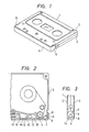
- Figs. 1, 2 and 3 show a tape cassette, such as a video tape cassette, disclosed in U.S. 4519521 (EP 136 849).
- the tape cassette shown in Fig. 1 is composed of a cassette casing 1 comprising an upper cassette half 2, a lower cassette half 3 attached to the upper cassette half 2, a lid or cover 4 pivotably mounted on the cassette casing 1 by a pair of side arms 5 on opposite ends of the lid 4.
- each of the side arms 5 has a pivot pin 6 projecting laterally therefrom and normally urged backwards by means of a leaf spring 7 disposed in the cassette casing 1.
- the pivot pin 6 extends through a hole 8 defined in a side wall of the cassette casing 1, the hole 8 having a substantially triangular or V shape (Fig. 3) tapered in a rearward direction of the tape cassette.
- the triangular hole 8 serves to guide and position the pivot pin 6 as it is turned when the lid 4 is opened and closed.
- the cassette casing 1 has openings 11,12,13 defined in a front side thereof by spaced partition bars 9, 10.
- the lid 4 has a projection 14 on an inner surface thereof, which can be fitted in the opening 12 or a recess defined in the front side of the cassette casing 1, for locking the lid 4 in the closed position.
- the tape cassette also includes a magnetic tape 15 wound around supply and takeup reels therein and extending through a prescribed path therein.
- the lid 4 can be angularly moved vertically (Fig. 1) to allow the tape to be played back on both tape sides or in opposite directions.
- the lid 4 can easily be unlocked and opened by turning the side arms 5 with a finger or a portion of a cassette recorder.
- a tape cassette according to the preamble of claim 1 and a cassette recorder according to the preamble of claim 6 are known from the GB-A-2 020 630.
- Such a tape cassette has at each side an opening, in which pivot pins of a lid are inserted.
- the pivot pins are formed at side arms of the lid and are pressed toward the rear side of the tape cassette by a spring member. Due to the design of the pivot pins having a rectangular or square cross-section resp. as well as due to the effect of the spring members, the lid is kept both in its closed and open position.
- the lid can easily open from its closed position unintendedly or can be opened by a non-skilled user, e.g. a child, resulting in disadvantageous external impacts on the tape material, e.g. as a consequence of dirt and dust and/or fingerprints of the user.
- this object is achieved with respect to the tape cassette by the features contained in the characterizing portion of the claim 1 and with respect to the cassette recorder by the features contained in the characterizing portion of the claim 6.
- the lid is kept between protrusions 18 in its closed position and has to be shifted toward the front side of the tape cassette to be swivelled into the open position. Due to the protrusions 18 the lid is protected from external impacts in its closed position so that it cannot be opened unintendedly and so that it is not possible for the user to seize the lid and thus open the tape cassette and get to the tape material.
- the lid can only be opened, if suitable unlocking elements engage in disengaging holes so as to accordingly shift the lid to the front and release it from its position secured between the protrusions.
- the usually present positioning member which safeguards a correct position of the tape cassette in the tape recorder, serves as unlocking element so that in spite of the complete locking of the tape cassette which is hard to release, no additional components are necessary for an unlocking mechanism.
- Fig. 4 shows a tape cassette according to an embodiment of the present invention, being in a closed state.
- the cassette casing 1 has positioning holes 16 for the insertion therethrough members for positioning the tape cassette which is loaded in a playback position in a cassette recorder.
- the side arms 5 of the lid 4 have rear end portions projecting respectively into the positioning holes 16.
- the cassette casing 1 includes a pair of horizontally spaced protective plates 17 extending from the lateral sides of the casing 1 in covering relation to the side arms 5, respectively.
- the protective plates 17 have a height L substantially equal to or greater than the height H of the lid 4.
- Fig. 5 shows the tape cassette in perspective with the lid 4 opened.
- the cassette casing 1 has a pair of vertically spaced protrusions 18 extending along upper and lower edges of the front side of the cassette casing 1 and defining a recess 19 therebetween.
- the lid 4 as it is in the closed position is fitted in the recess 19 between the protrusions 18 to guard against pivotal movement of the lid 4, as illustrated in Figs. 6 and 7.
- the lid 4 For opening the lid 4 from the closed position of Fig. 4, the lid 4 is required to be unlocked out of fitting engagement with the protrusions 18 on the front side of the tape cassette.
- the side arms 5 however cannot easily be pulled out with a finger since they are covered with the protective plates 17. Therefore, the lid 4 cannot be opened from the closed position by an intentional or inadvertent action.
- the lid 4 can be opened when inserted into a cassette recorder, as described below. As long as the tape cassette is out of the cassette recorder, therefore, the magnetic tape 15 is protected from being smeared with finger prints or pulled out and damaged by an intentional attempt.
- the cassette recorder has a positioning pin 20 disposed for registry with one of the positioning holes 16 when the tape cassette is loaded in the cassette recorder, and a lid opening pin 21 disposed for engagement with one of the side arms 5 of the lid 4 when the tape cassette is loaded in the cassette recorder.
- the tape cassette is moved in the direction of the arrow A normal to the plane of the tape cassette to insert the positioning pin 20 into the positioning hole 16 and also to cause the lid opening pin 21 to engage a proximal or lower end (Fig. 8) of the side arm 5.
- the lid opening pin 21 pushes the lower end of the side arm 5 to turn the lid 4 about the pivot pin 6 clockwise in the direction of the arrow C.
- the lid 4 After the lid 4 has turned for more than 45°, it starts being angularly moved automatically of its own accord under the force of the spring 7, until the lid 4 reaches a 90°-spaced opened position in which the lid 4 is held against an upper surface of the cassette casing 1.
- the above cassette loading operation or lid opening operation remains the same when the magnetic tape is to be played back on both tape sides or in the opposite directions.
- a rear edge of the lid 4 should be pushed in a forward direction. After the lid 4 has turned through 45°, it is forced by the spring 7 to return automatically to the closed position of Fig. 4.
- Fig. 9 shows another embodiment in which a lid 4 including side arms 5 has a height H smaller than the entire thickness L of the cassette casing 1, with recesses 22 defined adjacent to the protective plates 17.
- the recesses 22 can be utilized so that they can be detected by a suitable detector disposed in a cassette recorder to determine the orientation of the tape cassette as it is loaded or prevent the tape cassette from being inserted in a reverse direction.
- Tip or distal ends of the protective plates 17 may be employed to position the tape cassette in a cassette shifting means such as a cassette holder in the cassette recorder.
- FIG. 10 shows a tape cassette according to still another embodiment of the invention.
- a protective plate 17 has an recess 23 defined therein and extending toward a rear end of the side arm 5.
- the recess 23 allows the lid 4 to be unlocked by the side arm 5 accessed through the recess 23.
- Fig. 11 is illustrative of a still further embodiment in which a plurality of recesses 24 are defined in upper and lower edges of a front side of the cassette casing.
- the lid opening pins 21 (Fig. 8) can be located closely to the cassette casing 1 respectively at the recesses 24 for reliably engaging and lifting the lower edge of the lid 4.
- a protective plate 17 is composed of portions of the upper and lower casing halves 2, 3 coupled together by a mortise-and-tenon joint so that the assembled protective plate 17 is reinforced.
- the mortise-and-tenon joint employed has a mortise of a triangular cross section and a tenon of a complementary triangular cross section fitted in the mortise.
- Fig. 13 shows a protective plate 17 composed of upper and lower casing half portions 2, 3 joined to each other by a mortise-and-tenon joint comprising a mortise of a rectangular cross section and a tenon of a complementary rectangular cross section fitted in the mortise.
- the cassette casing can be assembled in the same manner as conventional cassette casings, and the protective plate 17 is reinforced against positional displacements and sluggish pivotal movement of the lid due to deformations or other difficulties.
- the protective plate may be composed of one of the upper and lower casing halves.
- the protective plate may be of a width smaller than the thickness of the tape cassette casing, and may have a round or tapered distal end which may be utilized to detect the orientation of the tape cassette as loaded into the cassette recorder or prevent the tape cassette from being loaded in a reverse direction.
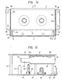
- Fig. 14 shows a cassette holder 25 in a cassette recorder.
- the cassette holder 25 has a pair of side walls 26 including respective extensions having inturned lips or abutments 27 on distal ends thereof.
- the cassette holder 25 also includes a pair of flanges 25a having guide holes 28 through which extend guide shafts for guiding the cassette holder 25 in its vertical movement.
- a reference line R passes through rear edges of the positioning holes 16 in the tape cassette.
- the cassette holder 25 serves to limit the position or interval in which the tape cassette is inserted when the distal ends of the protective plates 17 of the tape cassette are held against the abutments 27.
- the cassette holder 25 is in a first position in which the tape cassette can be inserted or removed.
- the cassette holder 25 has a lower panel 29, an upper panel 30, and a spring 31 attached to an inner surface of the upper panel 30 for resiliently depressing the upper surface of the inserted tape cassette to hold the latter in the cassette holder 25.
- the cassette holder 25 is guided in its vertical movement by the guide shafts, designated 32, 33, passing through the guide holes 28 (Fig. 14).
- a hub driver 34 is disposed on a lower chassis 41 of the cassette recorder for engaging a tape hub (not shown) in the tape cassette for supplying and winding a magnetic tape in the tape cassette.
- a pin 35 is mounted on the lower chassis 41 for limiting, with its upper surface, the height of a rear edge of the tape cassette when the latter is in a playback position in the cassette recorder.
- the tape cassette as it is in the playback position is urged by a spring 36 fastened together with the pin 35 to the lower chassis 41 and held resiliently against the rear edge of the tape cassette.
- the positioning pin 20 is also mounted on the lower chassis 41 and has a lower step or shoulder 38. The positioning pin 20 is inserted in the positioning hole 16 in the tape cassette as it is in the playback position for limiting longitudinal and transverse positions of the tape cassette in the playback position.
- the step 38 of the positioning pin 20 serves to limit the height of the front side of the tape cassette.
- the lid opening pin 21 is disposed on the lower chassis 41 for raising the lower edge of the lid 4 to open the lid 4 as the tape cassette is lowered by the cassette holder 25.
- the lower chassis 41 is coupled to an upper chassis 42 in vertically spaced relation by means of posts 43, only one shown.
- Fig. 16 shows the cassette holder 25 with the tape cassette 1 just inserted therein in the direction of the arrow D.
- the tape cassette inserted in the cassette holder 25 is lowered thereby into the playback position or a second position, in which the lid 4 is opened.
- the positioning pin 20 When the cassette holder 25 with the tape cassette therein is lowered from the position of Fig. 16, the positioning pin 20 is inserted into the positioning hole 16, pushes the rear end of the side arm 5 to displace the lid 4 forward away from the front side of the tape cassette. Upon continued downward movement of the cassette holder 25, the lower edge of the lid 4 is brought against the upper end of the lid opening pin 21 which lifts and turns the lid 4 to the open position.
- the tape cassette has been fully lowered, the tape cassette is limited in height by the pin 35, the step 38, and the spring 31, and resiliently urged in a forward direction under the resilient force of the spring 36 so as to be properly positioned in a back-and-forth direction by the positioning pin 20.
- the tape cassette is also positioned in a lateral direction by the positioning pin 20 fitted in the positioning hole 16.
- the cassette holder 25 When the tape cassette is to be removed, the cassette holder 25 is raised from the playback or second position (Fig. 17) to the eject or first position (Fig. 15), in which the tape cassette is ejected. While the tape cassette is being ejected out of the cassette holder 25, the upper edge (denoted 4a in Fig. 17) of the lid 4 as it is in the open position is engaged by a front end 31 a of the spring 31 and automatically closed. Thus, the tape cassette can be removed with the lid 4 in the closed position.
- the tape cassette as it is inserted can be positioned by the abutments 27 held against the front ends of the protective plates 17.
- the tape cassette 1 is lowered, it is positioned by the positioning pins 20 on the lower chassis 41 and the lid 4 is released in the closed position by the steps 38 of the positioning pins 20.
- the lid 4 is automatically opened by the lid opening pins 21.
- the lid 4 can automatically be closed by the spring 31.
- the cassette shifting means is not limited to the illustrated cassette holder, but may comprise a cam lever or the like for directly moving a tape cassette, a manually operated mechanism for loading a tape cassette, or an angularly movable cassette holder.
Landscapes
- Packaging Of Annular Or Rod-Shaped Articles, Wearing Apparel, Cassettes, Or The Like (AREA)
- Casings For Electric Apparatus (AREA)
Claims (7)
Applications Claiming Priority (4)
| Application Number | Priority Date | Filing Date | Title |
|---|---|---|---|
| JP12339/84 | 1984-01-25 | ||
| JP59012339A JPH0766649B2 (ja) | 1984-01-25 | 1984-01-25 | テープカセット |
| JP227154/84 | 1984-10-29 | ||
| JP59227154A JPS60157761A (ja) | 1984-10-29 | 1984-10-29 | カセツトレコ−ダ |
Publications (2)
| Publication Number | Publication Date |
|---|---|
| EP0153585A1 EP0153585A1 (de) | 1985-09-04 |
| EP0153585B1 true EP0153585B1 (de) | 1989-04-19 |
Family
ID=26347943
Family Applications (1)
| Application Number | Title | Priority Date | Filing Date |
|---|---|---|---|
| EP85100717A Expired EP0153585B1 (de) | 1984-01-25 | 1985-01-24 | Bandkassette und Kassettenrekorder für deren Verwendung |
Country Status (4)
| Country | Link |
|---|---|
| US (1) | US4740856A (de) |
| EP (1) | EP0153585B1 (de) |
| KR (1) | KR900006314B1 (de) |
| DE (1) | DE3569630D1 (de) |
Families Citing this family (10)
| Publication number | Priority date | Publication date | Assignee | Title |
|---|---|---|---|---|
| JPH0510299Y2 (de) * | 1985-05-15 | 1993-03-12 | ||
| JPH082824Y2 (ja) * | 1987-12-14 | 1996-01-29 | アルパイン株式会社 | カセットプレーヤ |
| AU664536B2 (en) * | 1990-05-11 | 1995-11-23 | Lcv Associates | Integrally molded recyclable video tape cassette |
| US5201476A (en) * | 1990-05-11 | 1993-04-13 | Paul J. Gelardi | Welded video cassette |
| US5240201A (en) * | 1990-05-11 | 1993-08-31 | Paul J. Gelardi | Integrally molded recyclable video tape cassette |
| US5092536A (en) * | 1990-05-11 | 1992-03-03 | Paul J. Gelardi | Integrally molded recyclable video tape cassette |
| US5114092A (en) * | 1991-01-10 | 1992-05-19 | Paul J. Gelardi | Low cost video cassette |
| DE69126847T2 (de) * | 1990-11-30 | 1998-02-12 | Matsushita Electric Ind Co Ltd | Bandkassette |
| JPH1097777A (ja) * | 1996-09-20 | 1998-04-14 | Sony Corp | ディスクカートリッジ |
| US7325763B1 (en) | 2006-09-21 | 2008-02-05 | International Business Machines Corporation | Magnetic tape guiding system guide roller with single flange oriented at lower debris tape edge |
Citations (1)
| Publication number | Priority date | Publication date | Assignee | Title |
|---|---|---|---|---|
| US4519521A (en) * | 1983-09-06 | 1985-05-28 | Matsushita Electric Industrial Co., Ltd. | Tape cassette |
Family Cites Families (6)
| Publication number | Priority date | Publication date | Assignee | Title |
|---|---|---|---|---|
| US4021006A (en) * | 1974-11-20 | 1977-05-03 | Matsushita Electric Industrial Co., Ltd. | Container for magnetic tape |
| NL165598C (nl) * | 1978-05-09 | 1981-04-15 | Philips Nv | Magneetbandcassette. |
| US4343024A (en) * | 1980-05-08 | 1982-08-03 | Tsutomu Kawai | Device for detecting tape end of magnetic recording apparatus |
| JPS57129285U (de) * | 1981-02-09 | 1982-08-12 | ||
| US4485988A (en) * | 1981-11-04 | 1984-12-04 | Matsushita Electric Industrial Co., Ltd. | Tape cassette |
| US4643304A (en) * | 1983-11-12 | 1987-02-17 | Hitachi Maxell, Ltd. | Tape cartridge with extending reference surfaces |
-
1985
- 1985-01-15 KR KR1019850000214A patent/KR900006314B1/ko not_active Expired
- 1985-01-24 US US06/694,321 patent/US4740856A/en not_active Expired - Fee Related
- 1985-01-24 EP EP85100717A patent/EP0153585B1/de not_active Expired
- 1985-01-24 DE DE8585100717T patent/DE3569630D1/de not_active Expired
Patent Citations (1)
| Publication number | Priority date | Publication date | Assignee | Title |
|---|---|---|---|---|
| US4519521A (en) * | 1983-09-06 | 1985-05-28 | Matsushita Electric Industrial Co., Ltd. | Tape cassette |
Also Published As
| Publication number | Publication date |
|---|---|
| EP0153585A1 (de) | 1985-09-04 |
| DE3569630D1 (en) | 1989-05-24 |
| US4740856A (en) | 1988-04-26 |
| KR900006314B1 (ko) | 1990-08-28 |
| KR850005699A (ko) | 1985-08-28 |
Similar Documents
| Publication | Publication Date | Title |
|---|---|---|
| EP0163293B1 (de) | Bandkassette | |
| SU1565357A3 (ru) | Кассета дл магнитной ленты | |
| US4504879A (en) | Disc drive arrangement | |
| DE69525800T2 (de) | Plattenkassette und Tablett zum Laden desselben | |
| DE3887950T2 (de) | Bandkassettenladesystem. | |
| EP0078696B1 (de) | Bandkassette | |
| GB2161642A (en) | Disc cassette | |
| EP0189324B1 (de) | Kassettenhalter in einem Aufnahme- und Wiedergabegerät für eine Magnetbandkassette | |
| EP0097964A1 (de) | Sperrelement für ein Deckel einer Magnetbandkassette | |
| EP0533463B1 (de) | Plattenkassette mit Falschaufzeichnungsschutzmechanismus | |
| US4740856A (en) | Tape cassette and cassette recorder using the same | |
| HK74394A (en) | Lock mechanism for tape protective closure for magnetic tape cassette | |
| US4554603A (en) | Adapter for a miniature type tape cassette | |
| US5596464A (en) | Locking assembly for a lid member of a tape cassette | |
| KR100453393B1 (ko) | 기록재생장치 | |
| US5189582A (en) | Recording latch | |
| JPS60175271A (ja) | テ−プカ−トリッジ | |
| KR100700679B1 (ko) | 테이프 카세트 | |
| EP0774755B1 (de) | Magnetaufzeichnungs-/-wiedergabegerät für Kassetten zweier verschiedener Grössen | |
| JPH0664819B2 (ja) | ディスクカセットのシャッタ開閉機構 | |
| JPH0424509Y2 (de) | ||
| JPH0441486Y2 (de) | ||
| JPH0452750Y2 (de) | ||
| JP3884765B2 (ja) | ディスクカートリッジ | |
| JP2508971B2 (ja) | テ―プカセット |
Legal Events
| Date | Code | Title | Description |
|---|---|---|---|
| PUAI | Public reference made under article 153(3) epc to a published international application that has entered the european phase |
Free format text: ORIGINAL CODE: 0009012 |
|
| AK | Designated contracting states |
Designated state(s): DE FR GB NL |
|
| 17P | Request for examination filed |
Effective date: 19851001 |
|
| 17Q | First examination report despatched |
Effective date: 19861215 |
|
| GRAA | (expected) grant |
Free format text: ORIGINAL CODE: 0009210 |
|
| AK | Designated contracting states |
Kind code of ref document: B1 Designated state(s): DE FR GB NL |
|
| REF | Corresponds to: |
Ref document number: 3569630 Country of ref document: DE Date of ref document: 19890524 |
|
| ET | Fr: translation filed | ||
| PLBE | No opposition filed within time limit |
Free format text: ORIGINAL CODE: 0009261 |
|
| STAA | Information on the status of an ep patent application or granted ep patent |
Free format text: STATUS: NO OPPOSITION FILED WITHIN TIME LIMIT |
|
| 26N | No opposition filed | ||
| PGFP | Annual fee paid to national office [announced via postgrant information from national office to epo] |
Ref country code: FR Payment date: 19950110 Year of fee payment: 11 |
|
| PGFP | Annual fee paid to national office [announced via postgrant information from national office to epo] |
Ref country code: GB Payment date: 19950116 Year of fee payment: 11 |
|
| PGFP | Annual fee paid to national office [announced via postgrant information from national office to epo] |
Ref country code: DE Payment date: 19950121 Year of fee payment: 11 |
|
| PG25 | Lapsed in a contracting state [announced via postgrant information from national office to epo] |
Ref country code: GB Effective date: 19960124 |
|
| PGFP | Annual fee paid to national office [announced via postgrant information from national office to epo] |
Ref country code: NL Payment date: 19960130 Year of fee payment: 12 |
|
| GBPC | Gb: european patent ceased through non-payment of renewal fee |
Effective date: 19960124 |
|
| PG25 | Lapsed in a contracting state [announced via postgrant information from national office to epo] |
Ref country code: FR Effective date: 19960930 |
|
| PG25 | Lapsed in a contracting state [announced via postgrant information from national office to epo] |
Ref country code: DE Effective date: 19961001 |
|
| REG | Reference to a national code |
Ref country code: FR Ref legal event code: ST |
|
| PG25 | Lapsed in a contracting state [announced via postgrant information from national office to epo] |
Ref country code: NL Effective date: 19970801 |
|
| NLV4 | Nl: lapsed or anulled due to non-payment of the annual fee |
Effective date: 19970801 |