EP0153607A2 - Jonction de référence dans un câble à isolation minérale à fils de thermocouples multiples - Google Patents
Jonction de référence dans un câble à isolation minérale à fils de thermocouples multiples Download PDFInfo
- Publication number
- EP0153607A2 EP0153607A2 EP85101103A EP85101103A EP0153607A2 EP 0153607 A2 EP0153607 A2 EP 0153607A2 EP 85101103 A EP85101103 A EP 85101103A EP 85101103 A EP85101103 A EP 85101103A EP 0153607 A2 EP0153607 A2 EP 0153607A2
- Authority
- EP
- European Patent Office
- Prior art keywords
- cable
- temperature measuring
- leads
- sheath
- measuring means
- Prior art date
- Legal status (The legal status is an assumption and is not a legal conclusion. Google has not performed a legal analysis and makes no representation as to the accuracy of the status listed.)
- Granted
Links
Images

Classifications
-
- G—PHYSICS
- G01—MEASURING; TESTING
- G01K—MEASURING TEMPERATURE; MEASURING QUANTITY OF HEAT; THERMALLY-SENSITIVE ELEMENTS NOT OTHERWISE PROVIDED FOR
- G01K7/00—Measuring temperature based on the use of electric or magnetic elements directly sensitive to heat ; Power supply therefor, e.g. using thermoelectric elements
-
- G—PHYSICS
- G01—MEASURING; TESTING
- G01K—MEASURING TEMPERATURE; MEASURING QUANTITY OF HEAT; THERMALLY-SENSITIVE ELEMENTS NOT OTHERWISE PROVIDED FOR
- G01K7/00—Measuring temperature based on the use of electric or magnetic elements directly sensitive to heat ; Power supply therefor, e.g. using thermoelectric elements
- G01K7/02—Measuring temperature based on the use of electric or magnetic elements directly sensitive to heat ; Power supply therefor, e.g. using thermoelectric elements using thermoelectric elements, e.g. thermocouples
- G01K7/10—Arrangements for compensating for auxiliary variables, e.g. length of lead
- G01K7/12—Arrangements with respect to the cold junction, e.g. preventing influence of temperature of surrounding air
- G01K7/13—Circuits for cold-junction compensation
Definitions
- the present invention relates to the transition between thermocouple leads and extension wires, and in particular to making the transition between thermocouple material leads and extension wire inside of a multi-conductor mineral insulated cable so that the transition can be made in a controlled manner, environmentally protected as close as possible to the thermocouple so that the length of the thermocouple material leads is minimal.
- thermocouple generates a voltage proportional to the junction temperature.
- the voltage measuring instrumentation is located outside of the reactor containment building, perhaps several hundred feet from the temperature measuring thermocouple.
- One known method to provide the voltage generated by a thermocouple to the processing Instrumentation is to connect the thermocouple leads directly to the processing instrumentation with long runs of thermocouple leads therebetween.
- the thermocouple leads are made of particular, expensive alloys depending upon the type of thermocouple used. It is, therefore, commercially desirable to make a transition from thermocouple leads to a lesser expensive conductor, such as copper wire, as close to the temperature measuring thermocouple as practical.
- thermocouple leads to a lesser expensive conductor includes terminating the leads of several temperature measuring thermocouples in a junction box within the reactor containment building with copper extension wires conducting the thermocouple generated voltage to the processing instrumentation outside the reactor containment building.
- the temperature inside the junction box is measured by another temperature measuring device so that the thermocouple generated voltage as measured by the processing instrumentation may be compensated for the voltage introduced at the intermediate junctions within the junction box.
- This technique requires thermocouple leads of substantial length be run from the temperature measuring thermocouples to a location within the containment building where it is convenient to locate a junction box.
- a temperature gradient may exist within the junction box such that all of the intermediate junctions within the junction box are not at the measured temperature of the junction box. Thus, an error is introduced in the measured temperatures due to a temperature gradient at the intermediate junctions within the junction box.
- the present invention provides apparatus for making a transition from leads of a temperature measuring thermocouple to extension wires as close to the temperature measuring thermocouple as practical.
- a transition from leads of a temperature measuring thermocouple to extension wires is made within a hermetically sealed cable sheath of small diameter.
- the interior of the cable sheath is shielded from electromagnetic radiation by an electrically conductive liner located within the sealed cable sheath.
- Intermediate junctions between thermocouple leads and extension wires are formed within the cable sheath.
- a thermally conductive, electrically insulating material surrounds the intermediate junctions. The temperature of the intermediate junctions is measured providing a signal to compensate the voltage generated by the temperature measuring thermocouples due to the thermoelectric effect of the intermediate junctions.
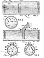
- FIG. 1 there is depicted therein apparatus 10 for making a transition within a cable from leads of a temperature measuring thermocouple to extension wires in accordance with the present invention.
- temperature measuring thermocouple leads 12-26 form intermediate junctions 28-42 where leads 12-26 juncture with extension wires 44-58, respectively.
- Leads 12-26 in pairs, form temperature measuring thermocouples (not shown).
- lead 12 made of a first alloy joins with lead 14 of a second alloy to form a temperature measuring thermocouple.
- Extension wires 44 and 46 conduct the voltage generated by the temperature measuring thermocouple across leads 12 to 14 from intermediate junctions 28 and 30 to the processing instrumentation (not shown).
- leads 16 and 18, leads 20 and 22, as well as leads 24 and 26 form temperature measuring thermocouples with extension wires 48 and 50, 52 and 54, and 56 and 58 conducting the thermocouple generated voltage back to the processing instrumentation.
- Leads 12-26, intermediate junctions 28-42 and extension wires 44-58 are enclosed in hermetically sealed cable sheath 60.
- Cable sheath 60 may be made of any suitable metal or material that provides an environmentally immune sheathing. Typically, cable sheath 60 is a stainless steel cable sheath 15 mils thick with a 0.6 centimeter inside diameter.
- Liner 62 forms a low resistance, electrically conductive path to ground coaxially with and along the inner surface of sheath 60.
- liner 62 is -copper, 15 mils thick with an outside diameter less than the inside diameter of sheath 60.
- a compensating temperature measuring element 64 is disposed within sheath 60 and preferably within liner 62 in the region of intermediate junctions 28-42.
- Thermally conductive, electrically insulating insulation 66 typically inorganic insulation such as silicon dioxide, fills the sheath in the region of intermediate junctions 28-42. Insulation 66 being thermally conductive assures that all intermediate junctions 28-42 are at the temperature measured by compensating temperature measuring element 64 which may be but is not limited to a thermocouple or resistance temperature device.
- compensating temperature measuring element 64 is located near intermediate junctions 28-42 such that compensating temperature measuring element 64 measures the temperature of intermediate junctions 28-42.
- the intermediate junctions 28-42 substantially form a circle such that compensating temperature measuring element 64, which is typically at the center, is not more than one inside diameter from any of intermediate junctions 28-42 and in the preferred embodiment is not more- than one inside radius from any of intermediate junctions 28-42. Due to the thermal conductivity of insulation 66 and the compactness of intermediate junctions 28-42, no temperature gradient exists across intermediate junctions 28-42 and compensating temperature element 64 such that the temperature measured by compensating temperature element 64 is the temperature of intermediate junctions 28-42.
- the leads 68 and 70 of compensating temperature measuring element 64 run along extension wires 44-68 within sheath 60 to the processing instrumentation.
- a transition is made within sheath 60 from an N conductor cable to an (N+2) conductor cable, where N is the number of thermocouple leads, typically an even number, and the quantity N+2 represents the number of conductors running within sheath 60 from intermediate junctions 28-42 back to the processing instrumentation.
- Figure 1 shows a transition from an 8 conductor to a 10 conductor cable.
- the invention is not limited to an 8 to 10 transition. The larger the value of N, the greater the economic savings.
- sheath 72 in an alternate embodiment of the invention shown in Figure 3 the leads of compensating temperature measuring element 64 that run back to the processing instrumentation pass through a second hermetically sealed cable sheath 72.
- Sheath 72 like sheath 60, is typically stainless steel, flexible and 15 mils thick, but sheath 72 has an internal diameter of about .3 centimeters (.125 in.). Sheath 72 need only be large enough to accommodate two conductors.
- Sheath 72 is hermetically sealed with sheath 60 such as by brazing or welding; the preferred embodiment shows circumscribing weld 76.
- Sheath 72 is lined with a low resistance, electrically conductive liner 78, typically a copper liner 10 mils thick, which is electrically conductive with liner 62.
- Liner 78 shields the interior of sheath 72 from electromagnetic radiation.
- the embodiment of the present invention shown in Figure 3 is particularly useful in measuring temperatures Inside of the reactor containment building of a nuclear power station where compensating temperature measuring element 64 is a thermocouple.
- Thermocouple lead conductors penetrate the containment building in a penetration separate from copper conductors. Since the two penetrations are physically separated, having a hermetically sealed cable housing the thermocouple leads separate from copper extension wires facilitates running the respective cables to an appropriate containment building penetration.
- Figure 4 shows a cross-section of the cable of Figure 3 disclosing an arrangement of intermediate junctions and compensating temperature measuring element 64 that form substantially a circle coaxially with the center of sheath 60.
- compensating temperature measuring element 64 is, in the preferred embodiment, not more than one inside radius of sheath 60 from any of Intermediate junctions 28-42.
- Other arrangements of intermediate junctions 28-42 and compensating temperature measuring element 64 are possible; it is only critical that intermediate junctions 28-42 be at the same temperature and that temperature be measured by compensating temperature measuring element 64.
- Figure 5 shows a variation of the cable cross-section wherein compensating temperature measuring element 64 is disposed within second sheath 72.
- compensating temperature measuring element 64 it is critical only that temperature measuring element 64 measure the temperature of intermediate junctions 28-42 and that no temperature gradient exist across intermediate junctions 28-42.
- compensating temperature element 64 responds rapidly to temperature variations surrounding the cable sheath due to the compactness of the transition and the thermal conductivity of the insulation as well as the sheath; albeit, a small time delay in heating or cooling the cable is introduced. In some applications a rapid thermal response is desirable. In other applications where thermal transients are superimposed on a slower temperature increase or decrease of the environment surrounding the cable sheath in the region of the transition, it is desirable to dampen the transient thermal response.
- a thermal dampening mass 140 is shown in Figure 6 surrounding and in heat exchange relation with cable sheaths 60 and 72 in the region of intermediate junctions 28-42 to achieve the thermal dampening.
- Mass 140 typically 25 centimeters by 25 centimeters by 10 centimeters (10 inches by 10 inches by 4 inches) of stainless steel, is formed of two portions 142 and 144 secured together by securing means 146. Mass 140 may surround one or-more cable sheaths 60, 72 in the region of intermediate junctions 28-42. Mass 140 dampens the thermal transients of the environment surrounding the cable sheaths by providing a larger mass that must change temperature before the temperature of intermediate junctions 28-42 as measured by_ compensating temperature element 64 changes.
- a semicircular groove is made in abutting surfaces of portions 142 and 144 of mass 140.
- a thermally conductive material may be applied to the exterior surface of cable sheath 60.
- a mold of the cable junctions may be made and the semicircular grooves in portions 142 and 144 machined to comform to the cable junction.
- Cable sheath 80 a hermetically sealed sheath is closed on the active end.
- Cable sheath 80 may be made of any suitable metal or material that provides an environmentally immune sheathing.
- cable sheath 80 is made of a stainless steel.
- Sheath 80 is lined with a low resistance, electrically conductive liner means 82 for shielding the interior of liner 82 from electromagnetic radiation.
- the active length of sheath 80 is defined to be coextensive with the length through which a temperature gradient measurement is desired.
- the active length of the sheath 80 is divided by the number of thermocouples used to measure the temperature gradient such that the thermocouples are spaced at substantially equal distances along sheath 80 through the active region 84. It is not essential that the thermocouples be substantially equally spaced; application specific factors may necessitate a nonuniform spacing.
- Figure 7 shows four thermocouples spaced substantially uniformly through active region 84 within sheath 80. Thermocouple 86 is placed near the closed end of sheath 80. Leads 88 and 90 of thermocouple 86 extend away from the closed end of sheath 80 and make a transition to extension wires 92 and 94, respectively, at intermediate junctions 96 and 98, respectively.
- Thermocouple 100 is located in the region of intermediate junctions 96 and 98 and functions both as a reference junction relative to the adjacent intermediate junctions 96 and 98 and simultaneously as a measure of temperature along active region 84.
- Leads 102 and 104 of thermocouple 100 extend away from the closed end of sheath 80 and juncture with extension wires 106 and 108, respectively, forming intermediate junctions 110 and 112, respectively.
- thermocouple 114 is located in the region of intermediate junctions 110 and 112 to function both as a reference junction relative to the adjacent intermediate junctions and simultaneously as a measure of the temperature along active region 84.
- Thermocouple leads 116 and 118 of thermocouple 114 extend away from the closed end of sheath 80 and juncture with extension wires 120 and 122, respectively, forming intermediate junctions 124 and 126.
- Thermocouple 128 is located in the region of intermediate junctions 124 and 126 and functions as a reference junction relative to the adjacent intermediate junctions and simultaneously as a measure of the temperature along active region 84: Leads 130 and 132 of thermocouple 128 as well as extension wires 92, 94, 106, 108, 120 and 122 run along the length of sheath 80 away from the closed end back to processing instrumentation (not shown).
- thermocouple 100 uses the voltage generated by thermocouple 100 to compensate the voltage generated by thermocouple 86 for the thermoelectric effect at intermediate junctions 96 and 98 due to the temperature difference between the physical locations of intermediate junctions 96 as well as 98 and thermocouple 86.
- the voltage generated by thermocouple 100 is compensated by the voltage generated by thermocouple 114 for the thermoelectric effect at intermediate junctions 110 and 112 due to the temperature difference between the physical locations of intermediate junctions 110 as well as 112 and thermocouple 100.
- thermocouple 114 the voltage generated by thermocouple 114 is compensated by the voltage generated by thermocouple 128 for the--themoelectric effect at intermediate junctions 124 and 126 due to the temperature difference between the physical locations of intermediate junctions 124 as well as 126 and thermocouple 114.
- Figures 8 and 9 are cross-sectional views of cable sheath 80 in active region 84. Both of the figures show the conductors equally spaced around an imaginary circle coaxially with the center of sheath 80 and within liner 82. It is not essential that the conductors be equally spaced. The spacing used is maintained by a thermally conductive, electrically insulating material 66 at least in the region of the thermocouples and intermediate junctions.
- thermocouples A minimum of two thermocouples are required to measure a temperature gradient. More than two thermocouples may be used depending upon the length of active region 84 and the resolution within the active region desired.
Landscapes
- Physics & Mathematics (AREA)
- General Physics & Mathematics (AREA)
- Measuring Temperature Or Quantity Of Heat (AREA)
- Monitoring And Testing Of Nuclear Reactors (AREA)
Applications Claiming Priority (2)
| Application Number | Priority Date | Filing Date | Title |
|---|---|---|---|
| US06/584,840 US4624582A (en) | 1984-02-29 | 1984-02-29 | Multi-wire mineral insulated cable thermocouple reference junction |
| US584840 | 1984-02-29 |
Publications (3)
| Publication Number | Publication Date |
|---|---|
| EP0153607A2 true EP0153607A2 (fr) | 1985-09-04 |
| EP0153607A3 EP0153607A3 (en) | 1987-05-27 |
| EP0153607B1 EP0153607B1 (fr) | 1992-01-22 |
Family
ID=24339001
Family Applications (1)
| Application Number | Title | Priority Date | Filing Date |
|---|---|---|---|
| EP85101103A Expired - Lifetime EP0153607B1 (fr) | 1984-02-29 | 1985-02-02 | Jonction de référence dans un câble à isolation minérale à fils de thermocouples multiples |
Country Status (6)
| Country | Link |
|---|---|
| US (1) | US4624582A (fr) |
| EP (1) | EP0153607B1 (fr) |
| JP (1) | JPS60203827A (fr) |
| KR (1) | KR900005777B1 (fr) |
| ES (1) | ES540498A0 (fr) |
| FI (1) | FI850792L (fr) |
Cited By (3)
| Publication number | Priority date | Publication date | Assignee | Title |
|---|---|---|---|---|
| EP0347490A3 (en) * | 1988-06-24 | 1990-04-18 | Yamari Industries, Limited | Method and apparatus for measuring temperature using thermocouple |
| EP0474674A4 (en) * | 1989-05-31 | 1992-05-06 | Rosemount Inc. | Thermocouple transmitter with cold junction compensation |
| DE102009008572A1 (de) * | 2009-02-12 | 2010-08-26 | Heraeus Sensor Technology Gmbh | Geschlossener Temperatursensor mit hoher Ansprechgeschwindigkeit |
Families Citing this family (17)
| Publication number | Priority date | Publication date | Assignee | Title |
|---|---|---|---|---|
| US4781057A (en) * | 1987-01-16 | 1988-11-01 | Hyfantis Jr George J | Method and apparatus for detecting leaks in a liquid-containing tank |
| US4862733A (en) * | 1987-01-16 | 1989-09-05 | Hyfantis Jr George J | Method and apparatus for detecting leaks in a liquid-containing tank |
| JPH073352B2 (ja) * | 1987-10-09 | 1995-01-18 | 株式会社日立製作所 | 熱式空気流量計 |
| GB2233457A (en) * | 1989-06-21 | 1991-01-09 | Schlumberger Technologies Ltd | Temperature reference junction for a multichannel temperature sensing system. |
| DE4102524C2 (de) * | 1990-01-30 | 2000-05-25 | Citizen Watch Co Ltd | Infrarotsensor |
| US5713668A (en) * | 1996-08-23 | 1998-02-03 | Accutru International Corporation | Self-verifying temperature sensor |
| US6219398B1 (en) * | 1998-07-28 | 2001-04-17 | Ce Nuclear Power Llc | Heated junction thermocouple cable arrangement |
| US6123675A (en) * | 1998-10-06 | 2000-09-26 | Trex Medical Corporation | Temperature gradient sensing probe for monitoring hyperthermic medical treatments |
| GB2344892B (en) * | 1998-12-16 | 2002-11-13 | Solartron Group Ltd | Cold junction compensation for multiple thermocouples |
| US6473708B1 (en) | 1999-12-20 | 2002-10-29 | Bechtel Bwxt Idaho, Llc | Device and method for self-verifying temperature measurement and control |
| EP1162438A1 (fr) * | 2000-06-09 | 2001-12-12 | Meteolabor Ag | Capteur de température |
| US7084342B2 (en) * | 2003-06-17 | 2006-08-01 | Watlow Electric Manufacturing Co. | Semi-compensated pins for cold junction compensation |
| US7011446B2 (en) * | 2003-07-29 | 2006-03-14 | Ametek, Inc. | Thermocouple junction box with isolated studs |
| GB2405476B (en) * | 2003-08-27 | 2006-07-19 | Gen Electric | Method, system and apparatus for measuring temperature with cold junction compensation |
| KR101034386B1 (ko) * | 2010-09-28 | 2011-05-16 | 주식회사 창성에이스산업 | 다중 위치 온도 측정 케이블 |
| US9068894B2 (en) * | 2012-11-26 | 2015-06-30 | The Boeing Company | Device for emulating temperature of a composite structure through a thermal cure cycle |
| US10976204B2 (en) * | 2018-03-07 | 2021-04-13 | Rosemount Inc. | Heat flux sensor with improved heat transfer |
Family Cites Families (19)
| Publication number | Priority date | Publication date | Assignee | Title |
|---|---|---|---|---|
| US1968534A (en) * | 1928-05-10 | 1934-07-31 | Allen Bradley Co | Apparatus for use in locating points of maximum or minimum temperatures |
| US2291051A (en) * | 1931-07-11 | 1942-07-28 | Joseph J Mascuch | Magneto shielding |
| US3069909A (en) * | 1959-05-11 | 1962-12-25 | Gen Electric | Temperature reference block |
| US3192770A (en) * | 1960-04-08 | 1965-07-06 | Michael E Bash | Multi-point measuring apparatus |
| US3281518A (en) * | 1963-11-26 | 1966-10-25 | Leeds & Northrup Co | Thermocouple assembly |
| US3312777A (en) * | 1964-08-19 | 1967-04-04 | Rochester Ropes Inc | Armored electrical cable breakout |
| US3439111A (en) * | 1966-01-05 | 1969-04-15 | Belden Mfg Co | Shielded cable for high frequency use |
| US3588776A (en) * | 1969-01-13 | 1971-06-28 | Lewis Eng Co | Safety cable |
| BE756568A (fr) * | 1969-10-09 | 1971-03-01 | Kabel Metallwerke Ghh | Cables electriques et procede pour leur fabrication |
| US3648523A (en) * | 1970-01-22 | 1972-03-14 | Joseph Kaye & Co | Uniform temperature reference apparatus |
| US3891791A (en) * | 1974-05-10 | 1975-06-24 | Gen Cable Corp | Communication cable with improved coated shield |
| DE2549140A1 (de) * | 1975-11-03 | 1977-05-05 | Gustav Kolb Fabrik Elektrokera | Steckverbindung fuer ein tauchthermoelement |
| FR2382000A1 (fr) * | 1977-02-25 | 1978-09-22 | Auxitrol | Rampe thermocouples pour la mesure de la moyenne de plusieurs temperatures |
| US4147061A (en) * | 1978-07-07 | 1979-04-03 | Avco Corporation | Thermocouple reference junction calibrator |
| US4265117A (en) * | 1979-01-26 | 1981-05-05 | Thoma Paul E | Surface temperature detecting apparatus |
| SE445258B (sv) * | 1980-08-28 | 1986-06-09 | Kobe Steel Ltd | Sett att overvaka avnotning av eldfasta veggar i en masugn |
| US4375009A (en) * | 1980-12-10 | 1983-02-22 | Hewlett-Packard Company | Shielded electrical cable |
| US4384793A (en) * | 1980-12-22 | 1983-05-24 | Uop Inc. | Temperature profile monitoring method and apparatus |
| US4441071A (en) * | 1982-03-31 | 1984-04-03 | Beckman Instruments, Inc. | Temperature compensation circuit for thermocouples |
-
1984
- 1984-02-29 US US06/584,840 patent/US4624582A/en not_active Expired - Fee Related
-
1985
- 1985-02-02 EP EP85101103A patent/EP0153607B1/fr not_active Expired - Lifetime
- 1985-02-18 ES ES540498A patent/ES540498A0/es active Granted
- 1985-02-22 KR KR1019850001107A patent/KR900005777B1/ko not_active Expired
- 1985-02-26 JP JP60035407A patent/JPS60203827A/ja active Granted
- 1985-02-27 FI FI850792A patent/FI850792L/fi not_active Application Discontinuation
Cited By (3)
| Publication number | Priority date | Publication date | Assignee | Title |
|---|---|---|---|---|
| EP0347490A3 (en) * | 1988-06-24 | 1990-04-18 | Yamari Industries, Limited | Method and apparatus for measuring temperature using thermocouple |
| EP0474674A4 (en) * | 1989-05-31 | 1992-05-06 | Rosemount Inc. | Thermocouple transmitter with cold junction compensation |
| DE102009008572A1 (de) * | 2009-02-12 | 2010-08-26 | Heraeus Sensor Technology Gmbh | Geschlossener Temperatursensor mit hoher Ansprechgeschwindigkeit |
Also Published As
| Publication number | Publication date |
|---|---|
| FI850792A7 (fi) | 1985-08-30 |
| FI850792L (fi) | 1985-08-30 |
| EP0153607B1 (fr) | 1992-01-22 |
| KR850006888A (ko) | 1985-10-21 |
| JPH0375051B2 (fr) | 1991-11-28 |
| ES8603075A1 (es) | 1985-12-01 |
| FI850792A0 (fi) | 1985-02-27 |
| EP0153607A3 (en) | 1987-05-27 |
| KR900005777B1 (ko) | 1990-08-11 |
| JPS60203827A (ja) | 1985-10-15 |
| US4624582A (en) | 1986-11-25 |
| ES540498A0 (es) | 1985-12-01 |
Similar Documents
| Publication | Publication Date | Title |
|---|---|---|
| US4624582A (en) | Multi-wire mineral insulated cable thermocouple reference junction | |
| US4186605A (en) | Set of thermocouples for measuring the average of several temperatures in a given space | |
| US4245500A (en) | Sensor for determining heat flux through a solid medium | |
| US3898431A (en) | Tubular electric heater with a thermocouple assembly | |
| US4906105A (en) | Measurement of thermal conditions | |
| US4377550A (en) | High temperature liquid level sensor | |
| US4603580A (en) | Unicable liquid level sensing system | |
| GB2062860A (en) | Temperature sensing assembly | |
| US5141335A (en) | Thermocouple connector | |
| US4627744A (en) | Temperature sensor utilizing thermal noise and thermal couple elements, and associated connecting cable | |
| US4654623A (en) | Thermometer probe for measuring the temperature in low-convection media | |
| US3956936A (en) | Temperature-measuring system | |
| JPH02144810A (ja) | 電力ケーブル及びその温度分布測定方法 | |
| CN101126653A (zh) | 低热阻热质量流量传感器 | |
| US3417617A (en) | Fluid stream temperature sensor system | |
| US3396357A (en) | Temperature sensing cable and method for making same | |
| US3834237A (en) | Thermocouple for surface temperature measurements | |
| US5048973A (en) | Plug-type heat flux gauge | |
| US5314247A (en) | Dual active surface, miniature, plug-type heat flux gauge | |
| KR20150081651A (ko) | 발전기 수냉각 권선의 온도 측정 장치 및 이를 이용한 수냉각 권선의 온도 측정 방법 | |
| US4637913A (en) | Device for measuring the power in a nuclear reactor | |
| EP4063815B1 (fr) | Dispositif de mesure de température | |
| US5328264A (en) | Compensation device for the cold junction of a thermocouple | |
| Ren et al. | Development of surface eroding thermocouples in small angle slot divertor in DIII-D | |
| US3605494A (en) | Heat flow calorimeter |
Legal Events
| Date | Code | Title | Description |
|---|---|---|---|
| PUAI | Public reference made under article 153(3) epc to a published international application that has entered the european phase |
Free format text: ORIGINAL CODE: 0009012 |
|
| AK | Designated contracting states |
Designated state(s): BE CH IT LI SE |
|
| PUAL | Search report despatched |
Free format text: ORIGINAL CODE: 0009013 |
|
| AK | Designated contracting states |
Kind code of ref document: A3 Designated state(s): BE CH IT LI SE |
|
| 17P | Request for examination filed |
Effective date: 19880120 |
|
| 17Q | First examination report despatched |
Effective date: 19891128 |
|
| GRAA | (expected) grant |
Free format text: ORIGINAL CODE: 0009210 |
|
| AK | Designated contracting states |
Kind code of ref document: B1 Designated state(s): BE CH IT LI SE |
|
| PGFP | Annual fee paid to national office [announced via postgrant information from national office to epo] |
Ref country code: CH Payment date: 19920204 Year of fee payment: 8 |
|
| PGFP | Annual fee paid to national office [announced via postgrant information from national office to epo] |
Ref country code: SE Payment date: 19920217 Year of fee payment: 8 |
|
| PGFP | Annual fee paid to national office [announced via postgrant information from national office to epo] |
Ref country code: BE Payment date: 19920325 Year of fee payment: 8 |
|
| ITF | It: translation for a ep patent filed | ||
| PLBE | No opposition filed within time limit |
Free format text: ORIGINAL CODE: 0009261 |
|
| STAA | Information on the status of an ep patent application or granted ep patent |
Free format text: STATUS: NO OPPOSITION FILED WITHIN TIME LIMIT |
|
| 26N | No opposition filed | ||
| PG25 | Lapsed in a contracting state [announced via postgrant information from national office to epo] |
Ref country code: SE Effective date: 19930203 |
|
| PG25 | Lapsed in a contracting state [announced via postgrant information from national office to epo] |
Ref country code: LI Effective date: 19930228 Ref country code: CH Effective date: 19930228 Ref country code: BE Effective date: 19930228 |
|
| BERE | Be: lapsed |
Owner name: COMBUSTION ENGINEERING INC. Effective date: 19930228 |
|
| REG | Reference to a national code |
Ref country code: CH Ref legal event code: PL |
|
| EUG | Se: european patent has lapsed |
Ref document number: 85101103.1 Effective date: 19930912 |