EP0153624A2 - Gaserzeugungsanlage (Wirbelschicht- oder Flugstrom-Druckreaktor mit Zyklonreinigung - Google Patents
Gaserzeugungsanlage (Wirbelschicht- oder Flugstrom-Druckreaktor mit Zyklonreinigung Download PDFInfo
- Publication number
- EP0153624A2 EP0153624A2 EP85101256A EP85101256A EP0153624A2 EP 0153624 A2 EP0153624 A2 EP 0153624A2 EP 85101256 A EP85101256 A EP 85101256A EP 85101256 A EP85101256 A EP 85101256A EP 0153624 A2 EP0153624 A2 EP 0153624A2
- Authority
- EP
- European Patent Office
- Prior art keywords
- gas
- raw gas
- cyclones
- cyclone
- cleaning
- Prior art date
- Legal status (The legal status is an assumption and is not a legal conclusion. Google has not performed a legal analysis and makes no representation as to the accuracy of the status listed.)
- Withdrawn
Links
Images

Classifications
-
- C—CHEMISTRY; METALLURGY
- C10—PETROLEUM, GAS OR COKE INDUSTRIES; TECHNICAL GASES CONTAINING CARBON MONOXIDE; FUELS; LUBRICANTS; PEAT
- C10J—PRODUCTION OF PRODUCER GAS, WATER-GAS, SYNTHESIS GAS FROM SOLID CARBONACEOUS MATERIAL, OR MIXTURES CONTAINING THESE GASES; CARBURETTING AIR OR OTHER GASES
- C10J3/00—Production of combustible gases containing carbon monoxide from solid carbonaceous fuels
- C10J3/46—Gasification of granular or pulverulent flues in suspension
- C10J3/48—Apparatus; Plants
-
- B—PERFORMING OPERATIONS; TRANSPORTING
- B04—CENTRIFUGAL APPARATUS OR MACHINES FOR CARRYING-OUT PHYSICAL OR CHEMICAL PROCESSES
- B04C—APPARATUS USING FREE VORTEX FLOW, e.g. CYCLONES
- B04C11/00—Accessories, e.g. safety or control devices, not otherwise provided for, e.g. regulators, valves in inlet or overflow ducting
-
- B—PERFORMING OPERATIONS; TRANSPORTING
- B04—CENTRIFUGAL APPARATUS OR MACHINES FOR CARRYING-OUT PHYSICAL OR CHEMICAL PROCESSES
- B04C—APPARATUS USING FREE VORTEX FLOW, e.g. CYCLONES
- B04C5/00—Apparatus in which the axial direction of the vortex is reversed
- B04C5/24—Multiple arrangement thereof
- B04C5/28—Multiple arrangement thereof for parallel flow
-
- C—CHEMISTRY; METALLURGY
- C10—PETROLEUM, GAS OR COKE INDUSTRIES; TECHNICAL GASES CONTAINING CARBON MONOXIDE; FUELS; LUBRICANTS; PEAT
- C10J—PRODUCTION OF PRODUCER GAS, WATER-GAS, SYNTHESIS GAS FROM SOLID CARBONACEOUS MATERIAL, OR MIXTURES CONTAINING THESE GASES; CARBURETTING AIR OR OTHER GASES
- C10J3/00—Production of combustible gases containing carbon monoxide from solid carbonaceous fuels
- C10J3/02—Fixed-bed gasification of lump fuel
- C10J3/06—Continuous processes
-
- C—CHEMISTRY; METALLURGY
- C10—PETROLEUM, GAS OR COKE INDUSTRIES; TECHNICAL GASES CONTAINING CARBON MONOXIDE; FUELS; LUBRICANTS; PEAT
- C10J—PRODUCTION OF PRODUCER GAS, WATER-GAS, SYNTHESIS GAS FROM SOLID CARBONACEOUS MATERIAL, OR MIXTURES CONTAINING THESE GASES; CARBURETTING AIR OR OTHER GASES
- C10J3/00—Production of combustible gases containing carbon monoxide from solid carbonaceous fuels
- C10J3/02—Fixed-bed gasification of lump fuel
- C10J3/20—Apparatus; Plants
-
- C—CHEMISTRY; METALLURGY
- C10—PETROLEUM, GAS OR COKE INDUSTRIES; TECHNICAL GASES CONTAINING CARBON MONOXIDE; FUELS; LUBRICANTS; PEAT
- C10J—PRODUCTION OF PRODUCER GAS, WATER-GAS, SYNTHESIS GAS FROM SOLID CARBONACEOUS MATERIAL, OR MIXTURES CONTAINING THESE GASES; CARBURETTING AIR OR OTHER GASES
- C10J3/00—Production of combustible gases containing carbon monoxide from solid carbonaceous fuels
- C10J3/46—Gasification of granular or pulverulent flues in suspension
- C10J3/54—Gasification of granular or pulverulent fuels by the Winkler technique, i.e. by fluidisation
- C10J3/56—Apparatus; Plants
-
- C—CHEMISTRY; METALLURGY
- C10—PETROLEUM, GAS OR COKE INDUSTRIES; TECHNICAL GASES CONTAINING CARBON MONOXIDE; FUELS; LUBRICANTS; PEAT
- C10J—PRODUCTION OF PRODUCER GAS, WATER-GAS, SYNTHESIS GAS FROM SOLID CARBONACEOUS MATERIAL, OR MIXTURES CONTAINING THESE GASES; CARBURETTING AIR OR OTHER GASES
- C10J3/00—Production of combustible gases containing carbon monoxide from solid carbonaceous fuels
- C10J3/72—Other features
- C10J3/78—High-pressure apparatus
-
- C—CHEMISTRY; METALLURGY
- C10—PETROLEUM, GAS OR COKE INDUSTRIES; TECHNICAL GASES CONTAINING CARBON MONOXIDE; FUELS; LUBRICANTS; PEAT
- C10J—PRODUCTION OF PRODUCER GAS, WATER-GAS, SYNTHESIS GAS FROM SOLID CARBONACEOUS MATERIAL, OR MIXTURES CONTAINING THESE GASES; CARBURETTING AIR OR OTHER GASES
- C10J3/00—Production of combustible gases containing carbon monoxide from solid carbonaceous fuels
- C10J3/72—Other features
- C10J3/82—Gas withdrawal means
- C10J3/84—Gas withdrawal means with means for removing dust or tar from the gas
-
- C—CHEMISTRY; METALLURGY
- C10—PETROLEUM, GAS OR COKE INDUSTRIES; TECHNICAL GASES CONTAINING CARBON MONOXIDE; FUELS; LUBRICANTS; PEAT
- C10J—PRODUCTION OF PRODUCER GAS, WATER-GAS, SYNTHESIS GAS FROM SOLID CARBONACEOUS MATERIAL, OR MIXTURES CONTAINING THESE GASES; CARBURETTING AIR OR OTHER GASES
- C10J2300/00—Details of gasification processes
- C10J2300/09—Details of the feed, e.g. feeding of spent catalyst, inert gas or halogens
- C10J2300/0913—Carbonaceous raw material
- C10J2300/093—Coal
Definitions
- the invention relates to a gas generating plant with a fluidized bed or entrained-flow pressure reactor in which coal is gasified, and with a device for cleaning the high-pressure raw gas.
- Fine coal is gasified under high pressure within the pressure reactor.
- the gas generated in this way can be used, for example, to generate energy.
- the capacity of the device assigned to the gas generating plant and used for cleaning the raw gas must also be adaptable.
- So-called wet scrubbing is generally used to clean a raw gas.
- This type of cleaning has the disadvantage, however, that the raw gas emerging from the gas generation plant is cooled relatively strongly. This cooling represents a loss of energy which adversely affects the overall efficiency of a plant containing the gas generating plant.
- the device used for cleaning the raw gas has at least two cyclones connected in parallel on the input side and in that the cyclones can be switched on or off individually.
- a cyclone is known per se in a different context than a device for cleaning a gas. As part of a Gaserzeu g but ungsstrom using a single cyclone would not be considered because of the lack of the necessary adaptability. However, if several cyclones are connected in parallel and these can be switched on and off by means of a corresponding control depending on the respective power requirement, the desired adaptability is ensured, while at the same time the use of a wet wash leading to energy loss can be avoided.
- the supply of the raw gas to the cyclones takes place by means of a pipeline into which, seen in the course of the line axis, one of the gas outlet connections leading to a cyclone opens laterally, and that in the Pipeline is arranged in the direction of the line axis movable, the line cross section locking piston.
- the end face of the closing piston facing the gas flow runs in an arc shape in the direction of the cross section of a gas outlet connection piece. In this way, an almost continuous deflection of the gas flow between the longitudinal axis of the pipeline and the axis of the gas outlet connection is possible.
- the gas generated in a compressed gas generator 10 enters a pipeline 11.
- the direction of flow is indicated by an arrow 12.
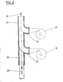
- In the pipeline 11 open approximately radially extending gas outlet stubs 13, each of which leads to the entrance of a cyclone 14, 15 and 16, respectively.
- Each of the three cyclones 14, 15 and 16 has a clean gas outlet 17 in its upper region, while a dust outlet 18 is located on the underside of the respective cyclone 14, 15 and 16.
- a closing piston 19 Arranged in the pipeline 11 is a closing piston 19 which is movable in the longitudinal direction thereof and which has the shape of a rod which extends through the pipeline 11.
- the inflow side of the closing piston 19 runs in an arc shape such that the radius of the curved inflow surface merges into a corresponding course of the respective gas outlet connection 13 as continuously as possible. This ensures a largely uniform deflection of the gas flow in the respective gas outlet connection 13.
- the locking piston 19 is connected to a drive, not shown here, by means of which an adjustment of the locking piston 19 in the directions indicated by the double arrow 20 is possible.
- the drive can be designed as a piston-cylinder arrangement or as a motor with a subsequent rack and pinion gear or the like.
- the cyclones 14, 15 and 16 are connected in parallel to one another.
- the closing piston 19 By adjusting the closing piston 19 into the corresponding position, it is possible to use only the cyclone designated by the reference number 14 To apply gas.
- the closing piston 19 is in a corresponding position on the gas outlet connection 13 assigned to the cyclone 14, or the closing piston 19 can be brought into the corresponding position on the gas outlet connection 13 of the cyclone 15 or the cyclone 16 in order to adapt to the amount of gas to be cleaned in each case , so that two or three cyclones are then in operation.
- This allows a good adaptation of the amount of gas coming from the compressed gas generator 10 to the amount of gas at which a cyclone of the type used has its optimum degree of purification.
- the individual cyclones can be switched on and off by means of the proposed device with only little technical effort and at very short notice.
Landscapes
- Chemical & Material Sciences (AREA)
- Engineering & Computer Science (AREA)
- Combustion & Propulsion (AREA)
- Oil, Petroleum & Natural Gas (AREA)
- Organic Chemistry (AREA)
- Cyclones (AREA)
- Devices And Processes Conducted In The Presence Of Fluids And Solid Particles (AREA)
Abstract
Description
- Die Erfindung betrifft eine Gaserzeugungsanlage mit einem Wirbelschicht- oder Flugstrom-Druckreaktor, in dem Kohle vergast wird, und mit einer Einrichtung zum Reinigen des unter hohem Druck stehenden Rohgases.
- Aus Gründen der Vereinfachung werden nachfolgend die beiden obengenannten Typen vom Gaserzeugern jeweils nur pauschal als Druckreaktoren bezeichnet.
- Innerhalb des Druckreaktors wird Feinkohle unter hohem Druck vergast. Das auf diesem Wege erzeugte Gas kann beispielsweise zur Energieerzeugung dienen.
- Im allgemeinen ist es erforderlich, das aus dem Druckreaktor austretende Gas zu reinigen, d.h. insbesondere von Staub und Teer zu befreien. Es ist andererseits aber auch meist erforderlich, die Leistung der jeweiligen Gaserzeugungsanlage an den jeweiligen Gasbedarf anzupassen. Dieser kann sich verhältnismäßig häufig und auch kurzfristig ändern, so daß es zweckmäßig ist, wenn die Gaserzeugungsanlage entsprechend anpaßbar ist.
- Wenn man vermeiden will, daß zwischen dieser und beispielsweise einem nachgeschalteten Kraftwerksteil ausreichend große Kapazitätspuffer eingeschaltet werden müssen, so wird auch die Kapazität der der Gaserzeugungsanlage zugeordneten und zum Reinigen des Rohgases dienenden Einrichtung anpaßbar sein müssen.
- Zum Reinigen eines Rohgases wird im allgemeinen eine sogenannte Naßwäsche verwendet. Diese Art der Reinigung hat jedoch den Nachteil, daß das aus der Gaserzeugungsanlage austretende Rohgas verhältnismäßig stark abgekühlt wird. Diese Abkühlung stellt einen Energieverlust dar, der den Gesamtwirkungsgrad einer die Gaserzeugungsanlage enthaltenden Anlage nachteilig beeinflußt.
- Hiervon ausgehend war es Aufgabe der vorliegenden Erfindung, eine Gaserzeugungsanlage der eingangs genannten Art so auszubilden, daß sie einerseits den Anforderungen an die Anpaßbarkeit der Leistung genügt und andererseits auch den ihr bisher anhaftenden Energieverlust weitgehend vermeidet.
- Diese Aufgabe wird erfindungsgemäß dadurch gelöst, daß die zum Reinigen des Rohgases dienende Einrichtung mindestens zwei eingangsseitig parallelgeschaltete Zyklone aufweist und daß die Zyklone einzeln zu- oder abschaltbar sind.
- Ein Zyklon ist an sich zwar in anderem Zusammenhang als zum Reinigen eines Gases dienende Einrichtung bekannt. Im Rahmen einer Gaserzeugungsanlage würde jedoch die Verwendung eines einzelnen Zyklons wegen des Fehlens der notwendigen Anpaßbarkeit nicht in Betracht kommen. Wenn man aber mehrere Zyklone parallel schaltet und diese mittels einer entsprechenden Steuerung in Abhängigkeit von dem jeweiligen Leistungsbedarf zu- und abschaltbar macht, ist die gewünschte Anpaßbarkeit gewährleistet, während gleichzeitig die Verwendung einer zu einem Energieverlust führenden Naßwäsche vermieden werden kann.
- Erfindungsgemäß wird weiterhin vorgeschlagen, daß die Zuführung des Rohgases zu den Zyklonen mittels einer Rohrleitung erfolgt, in die im Verlauf der Leitungsachse gesehen hintereinander jeweils ein zu einem Zyklon führender Gasaustrittsstutzen seitlich einmündet, und daß in der Rohrleitung ein in Richtung der Leitungsachse beweglichcr, den Leitungsquerschnitt sperrender Schließkolben angeordnet ist.
- Je nach Anzahl der verwendeten Zyklone wird eine entsprechende Anzahl von Gasaustrittsstutzen an die Rohrleitung angeschlossen. Je nach Stellung des Schließkolbens kann die jeweils gewünschte Anzahl von Gasaustrittsstutzen durch entsprechende Betätigung des Schließkolbens freigegeben werden. Besonders vorteilhaft ist es hierbei, daß sich diese Steuerbarkeit ohne die Verwendunq von Ventilen erreichen lä3t, die im Hinblick auf die Druck- und Temperaturverhältnisse sehr aufwendig sein müßten. Demgegenüber ist der für dieses Leitungssystem und den Schließkolben erforderliche technische Aufwand sehr gering.
- Um die Gasströmung im Bereich der Stirnfläche des Schließkolbens, also bei der Umlenkung in den jeweiligen Gasaustrittsstutzen, möglichst wirbelfrei führen zu können, wird erfindungsgemäß weiterhin vorgeschlagen, daß die der Gasströmung zugewandte Stirnfläche des Schließkolbens bogenförmig in Richtung auf den Querschnitt eines Gasaustrittsstutzens verläuft. Hierdurch wird also eine nahezu kontinuierliche Umlenkung der Gasströmung zwischen der Längsachse der Rohrleitung und der Achse des Gasaustrittsstutzens möglich.
- Nachfolgend wird ein Ausführungsbeispiel der Erfindung anhand einer Zeichnung näher beschrieben.
- Im einzelnen zeigen:
- Fig. 1 schematisch in perspektivischer Darstellung einen Druckgaserzeuger mit nachgeschalteten Zyklonen;
- Fig. 2 als Draufsicht auf einen Teil der Darstellung nach Fig. 1 einen Abschnitt der Rohrleitung mit dem Schließkolben.
- Das in einem Druckgaserzeuger 10 erzeugte Gas gelangt in eine Rohrleitung 11. Die Strömungsrichtung ist durch einen Pfeil 12 verdeutlicht. In die Rohrleitung 11 münden sich angenähert radial zu dieser erstreckende Gasaustrittsstutzen 13, von denen jeder zu dem Eingang eines Zyklons 14,15 beziehungsweise 16 führt. Jeder der drei Zyklone 14,15 und 16 hat in seinem oberen Bereich einen Reingasaustritt 17, während sich jeweils ein Staubaustritt 18 an der Unterseite des jeweiligen Zyklons 14,15 und 16 befindet.
- In der Rohrleitung 11 ist ein in Längsrichtung derselben beweglicher Schließkolben 19 angeordnet, der die Form einer sich durch die Rohrleitung 11 erstreckenden Stange hat. Die Anströmseite des Schließkolbens 19 verläuft bogenförmig derart, daß der Radius der gebogenen Anströmfläche in einen entsprechenden Verlauf des jeweiligen Gasaustrittsstutzens 13 möglichst kontinuierlich übergeht. Hierdurch wird eine weitgehend gleichmäßige Umlenkung der Gasströmung in den jeweiligen Gasaustrittsstutzen 13 gewährleistet.
- Der Schließkolben 19 ist mit einem hier nicht dargestellten Antrieb verbunden, durch den eine Verstellung des Schließkolbens 19 in den durch den Doppelpfeil 20 bezeichneten Richtungen möglich ist. Der Antrieb kann als Kolben-Zylinder-Anordnung oder als Motor mit nachgeschaltetem Zahnstangengetriebe oder dergleichen ausgebildet sein.
- Die Zyklone 14,15 und 16 sind zueinander parallel geschaltet. Durch Verstellung des Schließkolbens 19 in die entsprechende Position ist es möglich, entweder nur den mit der Bezugsziffer 14 bezeichneten Zyklon mit Gas zu beaufschlagen. In diesem Fall befindet sich der Schließkolben 19 in entsprechender Stellung an dem dem Zyklon 14 zugeordneten Gasaustrittsstutzen 13. Oder es kann der Schließkolben 19 zur Anpassung an die jeweils zu reinigende Gasmenge in die entsprechende Stellung am Gasaustrittsstutzen 13 des Zyklons 15 oder des Zyklons 16 gebracht werden, so daß dann zwei beziehungsweise drei Zyklone in Betrieb sind. Hierdurch ist eine gute Anpassung der jeweils aus dem Druckgaserzeuger 10 kommenden Gasmenge an diejenige Gasmenge möglich, bei der ein Zyklon der verwendeten Art seinen optimalen Reinigungsgrad hat. Das Zu- und Abschalten der einzelnen Zyklone kann mittels der vorgeschlagenen Einrichtung bei nur geringem technischen Aufwand und sehr kurzfristig erfolgen.
-
- 10 Druckgaserzeuger
- 11 Rohrleitung
- 12 Pfeil
- 13 Gasaustrittsstutzen
- 14 Zyklon
- 15 Zyklon
- 16 Zyklon
- 17 Reingasaustritt
- 18 Staubaustritt
- 19 Schließkolben
- 20 Doppelpfeil
Claims (3)
Applications Claiming Priority (2)
| Application Number | Priority Date | Filing Date | Title |
|---|---|---|---|
| DE3407157 | 1984-02-28 | ||
| DE3407157 | 1984-02-28 |
Publications (2)
| Publication Number | Publication Date |
|---|---|
| EP0153624A2 true EP0153624A2 (de) | 1985-09-04 |
| EP0153624A3 EP0153624A3 (de) | 1986-08-13 |
Family
ID=6229018
Family Applications (2)
| Application Number | Title | Priority Date | Filing Date |
|---|---|---|---|
| EP85101256A Withdrawn EP0153624A3 (de) | 1984-02-28 | 1985-02-07 | Gaserzeugungsanlage (Wirbelschicht- oder Flugstrom-Druckreaktor mit Zyklonreinigung |
| EP85101257A Withdrawn EP0159473A3 (de) | 1984-02-28 | 1985-02-07 | Gaserzeugungsanlage Festbett-Druckreaktor mit Zyklonreinigung |
Family Applications After (1)
| Application Number | Title | Priority Date | Filing Date |
|---|---|---|---|
| EP85101257A Withdrawn EP0159473A3 (de) | 1984-02-28 | 1985-02-07 | Gaserzeugungsanlage Festbett-Druckreaktor mit Zyklonreinigung |
Country Status (3)
| Country | Link |
|---|---|
| EP (2) | EP0153624A3 (de) |
| AU (1) | AU571310B2 (de) |
| ZA (2) | ZA851484B (de) |
Cited By (2)
| Publication number | Priority date | Publication date | Assignee | Title |
|---|---|---|---|---|
| EP0259577A3 (de) * | 1986-09-11 | 1988-09-14 | Man Gutehoffnungshütte Gmbh | Reaktor zur Kohlevergasung |
| FR2835764A1 (fr) * | 2002-02-14 | 2003-08-15 | Mann & Hummel Filter | Installation de cyclones commutable pour separer des particules ou des gouttelettes d'une veine de fluide, notamment pour un vehicule automobile |
Family Cites Families (4)
| Publication number | Priority date | Publication date | Assignee | Title |
|---|---|---|---|---|
| US1890070A (en) * | 1931-07-14 | 1932-12-06 | Prat Daniel Corp | Dust separator control |
| DE974634C (de) * | 1951-03-03 | 1961-03-09 | Ruhrgas Ag | Verfahren zur Brennglaserzeugung durch Vergasen eines feinkoernigen Brennstoffes |
| US3131043A (en) * | 1961-02-24 | 1964-04-28 | Aerotec Ind Inc | Gas scrubber |
| US4328006A (en) * | 1979-05-30 | 1982-05-04 | Texaco Development Corporation | Apparatus for the production of cleaned and cooled synthesis gas |
-
1985
- 1985-02-07 EP EP85101256A patent/EP0153624A3/de not_active Withdrawn
- 1985-02-07 EP EP85101257A patent/EP0159473A3/de not_active Withdrawn
- 1985-02-26 AU AU39133/85A patent/AU571310B2/en not_active Ceased
- 1985-02-27 ZA ZA851484A patent/ZA851484B/xx unknown
- 1985-02-27 ZA ZA851485A patent/ZA851485B/xx unknown
Cited By (2)
| Publication number | Priority date | Publication date | Assignee | Title |
|---|---|---|---|---|
| EP0259577A3 (de) * | 1986-09-11 | 1988-09-14 | Man Gutehoffnungshütte Gmbh | Reaktor zur Kohlevergasung |
| FR2835764A1 (fr) * | 2002-02-14 | 2003-08-15 | Mann & Hummel Filter | Installation de cyclones commutable pour separer des particules ou des gouttelettes d'une veine de fluide, notamment pour un vehicule automobile |
Also Published As
| Publication number | Publication date |
|---|---|
| EP0159473A3 (de) | 1986-08-20 |
| AU571310B2 (en) | 1988-04-14 |
| AU3913385A (en) | 1985-09-05 |
| EP0159473A2 (de) | 1985-10-30 |
| EP0153624A3 (de) | 1986-08-13 |
| ZA851484B (en) | 1985-11-27 |
| ZA851485B (en) | 1985-11-27 |
Similar Documents
| Publication | Publication Date | Title |
|---|---|---|
| DE2617772C2 (de) | Vorrichtung zum Abkühlen eines Spaltgasstromes | |
| DE3111502C2 (de) | Filternder Abscheider mit Gegenstromabreinigung der Filterelemente | |
| DE2732296A1 (de) | Vorrichtung zur nassreinigung von gasen | |
| EP0278287B1 (de) | Verfahren und Einrichtung zur Behandlung von körnigen Feststoffen in einer Wirbelschicht | |
| DE3340401C2 (de) | Einrichtung zum stufenweisen Druckabbau bei der Entspannung von insbesondere heißen Gasen | |
| EP0153624A2 (de) | Gaserzeugungsanlage (Wirbelschicht- oder Flugstrom-Druckreaktor mit Zyklonreinigung | |
| DE3430532A1 (de) | Gaserzeugungsanlage | |
| EP0247504B1 (de) | Verfahren zur Herstellung von Wasserstoff und Kohlenmonoxid enthaltenen Gasen aus festen Brennstoffen | |
| DE3872357T2 (de) | Wasserbadbenetzungsvorrichtung. | |
| DE3430533A1 (de) | Gaserzeugungsanlage | |
| DE3124125C2 (de) | ||
| EP0783590A1 (de) | Verfahren zum reduzieren von oxidhältigem material und anlage zur durchführung des verfahrens | |
| DE1442613B2 (de) | Vorrichtung zum behandeln von feststoffteilchen, insbesondere kohleteilchen, in einem fliessbett | |
| DE1105895B (de) | Verfahren und Vorrichtung zum Reinigen der Kuehlwasserrohre von Waermeaustauschern durch Zufuehrung von Druckgas waehrend des Betriebes | |
| DE2016205A1 (de) | Verfahren und Einrichtung zum Aus gleichen der Gasdrucke von Schleusen kammern und Ofenraum von Schachtofen, insbesondere von Hochofen | |
| DE3044909C2 (de) | ||
| DE19647868C1 (de) | Rußbläser | |
| WO1993000148A1 (de) | Nassreinigungseinrichtung, insbesondere zum abscheiden gasförmiger und/oder flüssiger und/oder fester verunreinigungen aus gasströmen | |
| DE3233445A1 (de) | Entspannungsventil fuer die entspannung von hydrierrueckstaenden der kohle- und schweroelhydrierung | |
| DE2836772C2 (de) | Vorrichtung zum Entfernen von Feststoffen aus einem in einem Wirbelbett behandelten Gas | |
| EP1507579A1 (de) | Reinigungsvorrichtung f r rohrf rmige filterelemente | |
| DE3102403A1 (de) | Fluidreinigungssystem | |
| DD247387A1 (de) | Vorrichtung zur druckentspannung gasbeladener und/oder feststoffhaltiger fluessigkeiten | |
| DE2607743A1 (de) | Verfahren zum vergasen fester brennstoffe, insbesondere kohle | |
| DE506867C (de) | Einrichtung zum Speisen eines Blasrohres mit Druckluft, insbesondere fuer Russblaeser |
Legal Events
| Date | Code | Title | Description |
|---|---|---|---|
| PUAI | Public reference made under article 153(3) epc to a published international application that has entered the european phase |
Free format text: ORIGINAL CODE: 0009012 |
|
| AK | Designated contracting states |
Designated state(s): BE DE FR GB NL |
|
| PUAL | Search report despatched |
Free format text: ORIGINAL CODE: 0009013 |
|
| AK | Designated contracting states |
Kind code of ref document: A3 Designated state(s): BE DE FR GB NL |
|
| 17P | Request for examination filed |
Effective date: 19860703 |
|
| 17Q | First examination report despatched |
Effective date: 19870811 |
|
| STAA | Information on the status of an ep patent application or granted ep patent |
Free format text: STATUS: THE APPLICATION HAS BEEN WITHDRAWN |
|
| 18W | Application withdrawn |
Withdrawal date: 19871002 |
|
| RIN1 | Information on inventor provided before grant (corrected) |
Inventor name: SCHAEFER, WOLFGANG, DR.-ING. |