EP0153668A2 - Machine à plier - Google Patents
Machine à plier Download PDFInfo
- Publication number
- EP0153668A2 EP0153668A2 EP85101622A EP85101622A EP0153668A2 EP 0153668 A2 EP0153668 A2 EP 0153668A2 EP 85101622 A EP85101622 A EP 85101622A EP 85101622 A EP85101622 A EP 85101622A EP 0153668 A2 EP0153668 A2 EP 0153668A2
- Authority
- EP
- European Patent Office
- Prior art keywords
- folding
- frame
- unit
- frame bridge
- bridge
- Prior art date
- Legal status (The legal status is an assumption and is not a legal conclusion. Google has not performed a legal analysis and makes no representation as to the accuracy of the status listed.)
- Granted
Links
- 230000008878 coupling Effects 0.000 claims 1
- 238000010168 coupling process Methods 0.000 claims 1
- 238000005859 coupling reaction Methods 0.000 claims 1
- 230000006835 compression Effects 0.000 description 2
- 238000007906 compression Methods 0.000 description 2
- 238000011161 development Methods 0.000 description 2
- 230000018109 developmental process Effects 0.000 description 2
- 238000010276 construction Methods 0.000 description 1
- 230000000694 effects Effects 0.000 description 1
- 230000008030 elimination Effects 0.000 description 1
- 238000003379 elimination reaction Methods 0.000 description 1
- 230000001771 impaired effect Effects 0.000 description 1
- 230000002452 interceptive effect Effects 0.000 description 1
- 230000001960 triggered effect Effects 0.000 description 1
Images
Classifications
-
- B—PERFORMING OPERATIONS; TRANSPORTING
- B65—CONVEYING; PACKING; STORING; HANDLING THIN OR FILAMENTARY MATERIAL
- B65H—HANDLING THIN OR FILAMENTARY MATERIAL, e.g. SHEETS, WEBS, CABLES
- B65H45/00—Folding thin material
- B65H45/12—Folding articles or webs with application of pressure to define or form crease lines
- B65H45/14—Buckling folders
- B65H45/142—Pocket-type folders
-
- B—PERFORMING OPERATIONS; TRANSPORTING
- B65—CONVEYING; PACKING; STORING; HANDLING THIN OR FILAMENTARY MATERIAL
- B65H—HANDLING THIN OR FILAMENTARY MATERIAL, e.g. SHEETS, WEBS, CABLES
- B65H45/00—Folding thin material
- B65H45/12—Folding articles or webs with application of pressure to define or form crease lines
- B65H45/18—Oscillating or reciprocating blade folders
Definitions
- the invention relates to a folding machine with at least one upsetting unit and a plurality of folding unit units, used for the parallel fold, for folding and cross-folds, as is also known as a "combined folding machine" and for folding sheets of sheet-like materials, in particular printed ones Paper sheet is used.
- a folding blade unit for the cross fold is arranged on a frame side wall.
- the position of the folding blade corresponds to the center of the machine format, so that the folding blade unit is of different lengths for different machine widths.
- a larger machine width requires a stable and torsion-free attachment of the folding blade unit to a correspondingly stable frame side wall.
- this one-sided fastening of the folding sword unit to a side wall of the frame is no longer up to the requirements of fold fold quality; Vibrations of the bracket and the frame side wall impair the exact fold breakage.
- the invention is therefore based on the object of eliminating the disadvantages mentioned of the conventional designs of combination folding machines and thereby ensuring a stable, vibration-free and torsion-free arrangement of the folding blade units for different machine widths.
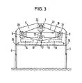
- the folding blade units with cantilevers are attached to a rigid frame bridge extending between and fixed to the frame side walls at the exit end of the machine frame and in that the frame side walls extend deep recesses over the area of the folding blade units exhibit.
- the setting elements for the operator are clearly visible and freely accessible, such as the sheet hold-down device arranged above the conveying device, the sheet stops and the associated operating elements, but also the knife shafts or output shafts with transport rollers and cutting device arranged at the output of the compression fold unit used for the parallel break - or perforating devices.
- the sheet adjustment and the stub sheet removal are much easier and faster to carry out than with the previously known types.
- the invention enables an advantageous further development to the effect that the folding blade units carried by the rack bridge are driven coupled by a common drive, preferably in such a way that they are driven by an electric motor attached to the frame bridge via an element, for example a toothed belt, which couples the drive wheels of the folding blade units and runs parallel to the plane of the frame bridge.
- a common drive preferably in such a way that they are driven by an electric motor attached to the frame bridge via an element, for example a toothed belt, which couples the drive wheels of the folding blade units and runs parallel to the plane of the frame bridge.
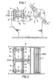
- a sheet feeder of known design, not shown, for separating and delivering the paper sheets is followed by a compression folding unit formed from folding rollers 1 and folding pockets 2 for the parallel break, at the output of which knife shafts or output shafts with transport rollers and cutting or perforating devices 15, 16 are provided.
- a rigid frame bridge 5 which extends between these side walls and is fastened to them.
- Brackets 6 are attached to it, which in the example shown are formed by hollow profile pieces of equal length and of a sufficiently large cross-section which provides resistance to vibrations.
- Such a boom 6 fastened in the central region of the frame bridge 5 carries a cross-fold folding sword unit 7 with a folding sword 12.
- three-fold folding-sword unit 8 with a folding sword 13 and a folding-sword unit 9 with a folding sword 14 are held on the same booms, which are lower than the middle boom 6.
- the folding blade units 7, 8 and 9 are driven together by an electric motor 17 which is on or in the lower part of the frame bridge 5 is mounted so that its output element is on the back of the frame bridge 5.
- the drive wheels 20, 21 and 22 of the folding blade units 7, 8 and 9 are also mounted there.
- the gear means for transmitting motion to the folding swords go through the hollow profiles 6.
- the machine is equipped with devices, known per se, not shown, for laying out the sheets after the parallel break or after the cross break or after one or the other of the selectable three breaks.
- An opening 18 is provided in the frame bridge 15 for laying out sheets which are only subjected to the parallel break.
- the conveyor devices of a known type, which forward the sheets after each fold.
- Associated folding rollers 10 are mounted below the cross-fold folding blade unit 7, and folding rollers 11 and 9 are stored below the three-folding folding blade units 8 and 9.
- the folding sheets coming from the folding rollers 1 of the parallel folding unit do not arrive by means of the Drawn conveyor below the cross-fold folding sword unit 7, where they are driven by the folding sword 12 between the folding rollers 10.
- the machine is set up so that the sheet provided with the cross fold is passed on or processed. It can thus be led out of the machine immediately and laid out or, depending on the choice, fed to one of the three-break folding units on the machine, either to the right or left of the cross-fold folding unit, where it is in the three-break folding unit 8 from the folding sword 13 or in the three-fold folding blade unit 9 is driven by the folding blade 14 between the folding rollers 11.
Landscapes
- Folding Of Thin Sheet-Like Materials, Special Discharging Devices, And Others (AREA)
- Making Paper Articles (AREA)
- Bending Of Plates, Rods, And Pipes (AREA)
Applications Claiming Priority (2)
| Application Number | Priority Date | Filing Date | Title |
|---|---|---|---|
| DE8406396U | 1984-03-01 | ||
| DE8406396 | 1984-03-01 |
Publications (3)
| Publication Number | Publication Date |
|---|---|
| EP0153668A2 true EP0153668A2 (fr) | 1985-09-04 |
| EP0153668A3 EP0153668A3 (en) | 1986-03-12 |
| EP0153668B1 EP0153668B1 (fr) | 1988-05-11 |
Family
ID=6764253
Family Applications (1)
| Application Number | Title | Priority Date | Filing Date |
|---|---|---|---|
| EP85101622A Expired EP0153668B1 (fr) | 1984-03-01 | 1985-02-14 | Machine à plier |
Country Status (4)
| Country | Link |
|---|---|
| EP (1) | EP0153668B1 (fr) |
| JP (1) | JP2513598B2 (fr) |
| DD (1) | DD241729A5 (fr) |
| DE (1) | DE3562605D1 (fr) |
Cited By (1)
| Publication number | Priority date | Publication date | Assignee | Title |
|---|---|---|---|---|
| EP1156004A3 (fr) * | 2000-05-15 | 2004-03-03 | Heidelberger Druckmaschinen Aktiengesellschaft | Appareil de pliage |
Families Citing this family (1)
| Publication number | Priority date | Publication date | Assignee | Title |
|---|---|---|---|---|
| DD297131A5 (de) * | 1990-08-16 | 1992-01-02 | Brehmer Buchbindereimaschinen Gmbh,De | Falzmesserhalterung |
Family Cites Families (4)
| Publication number | Priority date | Publication date | Assignee | Title |
|---|---|---|---|---|
| GB1205581A (en) * | 1967-01-09 | 1970-09-16 | Camco Machinery Ltd | Improvements in or relating to paper sheet folding machines |
| GB1219409A (en) * | 1967-05-12 | 1971-01-13 | Camco Machinery Ltd | Improvements in or relating to paper sheet folding machines |
| DE3147064A1 (de) * | 1981-11-27 | 1983-06-01 | Stahl Gmbh & Co Maschinenfabrik, 7140 Ludwigsburg | Falzwerkverband |
| JP5528987B2 (ja) | 2010-11-11 | 2014-06-25 | ピーエスフォー ルクスコ エスエイアールエル | 半導体装置 |
-
1985
- 1985-02-14 EP EP85101622A patent/EP0153668B1/fr not_active Expired
- 1985-02-14 DE DE8585101622T patent/DE3562605D1/de not_active Expired
- 1985-02-20 JP JP60030669A patent/JP2513598B2/ja not_active Expired - Fee Related
- 1985-02-26 DD DD85273557A patent/DD241729A5/de not_active IP Right Cessation
Cited By (2)
| Publication number | Priority date | Publication date | Assignee | Title |
|---|---|---|---|---|
| EP1156004A3 (fr) * | 2000-05-15 | 2004-03-03 | Heidelberger Druckmaschinen Aktiengesellschaft | Appareil de pliage |
| US6852073B2 (en) | 2000-05-15 | 2005-02-08 | Heidelberger Druckmaschinen Ag | Folder apparatus |
Also Published As
| Publication number | Publication date |
|---|---|
| EP0153668B1 (fr) | 1988-05-11 |
| DD241729A5 (de) | 1986-12-24 |
| JPS60191967A (ja) | 1985-09-30 |
| JP2513598B2 (ja) | 1996-07-03 |
| EP0153668A3 (en) | 1986-03-12 |
| DE3562605D1 (en) | 1988-06-16 |
Similar Documents
| Publication | Publication Date | Title |
|---|---|---|
| EP0986478B1 (fr) | Procédé pour enfiler une bande partielle de papier | |
| DE4344362C2 (de) | Vorrichtung zum Herstellen von Falzprodukten | |
| DE3405252C2 (de) | Vorrichtung zum Zerschneiden eines Schaumkunststoffkörpers | |
| DE29501537U1 (de) | Bogenleiteinrichtung mit Luftversorgungskästen | |
| EP1007461B1 (fr) | Plieuse a poches comportant deux ou trois poches de pliage | |
| DE2657789A1 (de) | Einrichtung zum einziehen einer papierbahn in den falzapparat einer rotationsdruckmaschine | |
| EP0685335B1 (fr) | Appareil de pliage à triangle double | |
| EP0318852B1 (fr) | Super structure pour une machine à plier | |
| EP1456107A1 (fr) | Dispositif de production de produits plies | |
| EP0153668B1 (fr) | Machine à plier | |
| EP1015678A1 (fr) | Dispositif permettant de tendre des fils de chaine sur une machine a tendre les fils de chaine | |
| DE3330167C2 (fr) | ||
| EP4178898A1 (fr) | Plieuse comprenant un groupe de pliage à lame et procédé de pliage de produits à plier au moyen d'un groupe de pliage à lame | |
| DE3407601A1 (de) | Falzmaschine | |
| DE2438607C2 (de) | Transportvorrichtung für blattförmige Materialien | |
| DE9312170U1 (de) | Falzapparat für Rollenrotationsdruckmaschinen | |
| DE8501065U1 (de) | Vorrichtung zum Zuführen von Strängen zu einem Falzapparat | |
| EP0774351B1 (fr) | Appareil pour fixer électrostatiquement un produit plat multi-couche | |
| EP1348665A2 (fr) | Plieuse avec un module pour plier des feuilles en direction perpendiculaire au pli transversal | |
| DE524644C (de) | Falzmaschine | |
| DE2937312A1 (de) | Vorrichtung zum abreissen von einzelblaettern von einer quer perforierten endlosbahn | |
| DE1921968C (de) | Anlage zur Herstellung von Förderbändern | |
| DE9320814U1 (de) | Vorrichtung zum Herstellen von Falzprodukten | |
| EP1412270A1 (fr) | Dispositif d'empilage de feuilles, en particulier de feuilles de papier ou de carton, transportees par margeur a nappe, sur des palettes | |
| DE9421467U1 (de) | Papierbahnzuführung für einen Falzapparat |
Legal Events
| Date | Code | Title | Description |
|---|---|---|---|
| PUAI | Public reference made under article 153(3) epc to a published international application that has entered the european phase |
Free format text: ORIGINAL CODE: 0009012 |
|
| AK | Designated contracting states |
Designated state(s): CH DE IT LI |
|
| PUAL | Search report despatched |
Free format text: ORIGINAL CODE: 0009013 |
|
| AK | Designated contracting states |
Kind code of ref document: A3 Designated state(s): CH DE IT LI |
|
| 17P | Request for examination filed |
Effective date: 19860729 |
|
| 17Q | First examination report despatched |
Effective date: 19870722 |
|
| GRAA | (expected) grant |
Free format text: ORIGINAL CODE: 0009210 |
|
| AK | Designated contracting states |
Kind code of ref document: B1 Designated state(s): CH DE IT LI |
|
| REF | Corresponds to: |
Ref document number: 3562605 Country of ref document: DE Date of ref document: 19880616 |
|
| ITF | It: translation for a ep patent filed | ||
| PGFP | Annual fee paid to national office [announced via postgrant information from national office to epo] |
Ref country code: CH Payment date: 19890217 Year of fee payment: 5 |
|
| ITTA | It: last paid annual fee | ||
| PLBE | No opposition filed within time limit |
Free format text: ORIGINAL CODE: 0009261 |
|
| STAA | Information on the status of an ep patent application or granted ep patent |
Free format text: STATUS: NO OPPOSITION FILED WITHIN TIME LIMIT |
|
| 26N | No opposition filed | ||
| PG25 | Lapsed in a contracting state [announced via postgrant information from national office to epo] |
Ref country code: LI Effective date: 19900228 Ref country code: CH Effective date: 19900228 |
|
| REG | Reference to a national code |
Ref country code: CH Ref legal event code: PL |
|
| PGFP | Annual fee paid to national office [announced via postgrant information from national office to epo] |
Ref country code: DE Payment date: 19950126 Year of fee payment: 11 |
|
| PG25 | Lapsed in a contracting state [announced via postgrant information from national office to epo] |
Ref country code: DE Effective date: 19961101 |