EP0153698A2 - Outil pour le travail du sol - Google Patents
Outil pour le travail du sol Download PDFInfo
- Publication number
- EP0153698A2 EP0153698A2 EP85101870A EP85101870A EP0153698A2 EP 0153698 A2 EP0153698 A2 EP 0153698A2 EP 85101870 A EP85101870 A EP 85101870A EP 85101870 A EP85101870 A EP 85101870A EP 0153698 A2 EP0153698 A2 EP 0153698A2
- Authority
- EP
- European Patent Office
- Prior art keywords
- support arm
- plow
- piece
- frame
- main frame
- Prior art date
- Legal status (The legal status is an assumption and is not a legal conclusion. Google has not performed a legal analysis and makes no representation as to the accuracy of the status listed.)
- Withdrawn
Links
Images
Classifications
-
- A—HUMAN NECESSITIES
- A01—AGRICULTURE; FORESTRY; ANIMAL HUSBANDRY; HUNTING; TRAPPING; FISHING
- A01B—SOIL WORKING IN AGRICULTURE OR FORESTRY; PARTS, DETAILS, OR ACCESSORIES OF AGRICULTURAL MACHINES OR IMPLEMENTS, IN GENERAL
- A01B15/00—Elements, tools, or details of ploughs
Definitions
- the invention relates to a tillage implement, in particular a plow, with frame parts arranged on a main frame for receiving plow bodies and skimmers or disc coulters, which are detachably connected to the frame parts by means of fastening elements.
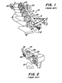
- a plow is already known (see FIGS. 1 and 2 of the same application) which has a main frame on which numerous frame parts are arranged at a distance from one another.
- the frame parts are used to hold plowshares and disc coulters.
- the disc coulters each have a holder with vertically extending bolts, which are received in U-bracket screws.
- the individual U-bracket screws are located in the holes provided in the frame parts and are secured with nuts.
- the invention has for its object to connect the individual tillage tools or skimmers or disc coulters to the frame parts in such a way that even under extreme loads there is no independent adjustment of the tillage tools.
- This object has been achieved in that the frame part connected to the main frame has at its front end an arc piece to which a support arm for receiving the skimmer is adapted, the opposite surfaces of the support arm and the arc piece having interlocking teeth. Due to the advantageous design and arrangement of the front end of the frame parts and attached to it closed support arms, a perfect fit of the tillage tools is guaranteed even in extreme working conditions.
- the support arms are adapted to the curved piece of the frame part, the surfaces of the support arms and the curved pieces lying against one another being provided with teeth which prevent the individual parts from slipping.
- the mutually abutting surfaces of the support arm and arch piece and the associated teeth run in the vertical plane and are pressed against one another by means of screw bolts and that the screw bolts are accommodated in the longitudinal slots provided in the arch piece and the support arm and the skimmer horizontally displaceable and vertically immovable.
- 10 denotes a plow with share bodies, which has a pull rod 12, a main frame 14 and numerous plow bodies 16.
- Each plow body consists of a mouldboard with the associated coulter 18.
- the mouldboard with the associated coulter 18 is connected to the main frame 14 by means of fastening elements 20.
- At the end of the main frame there are support wheels 22 and 24.
- the plow body 16 with the associated share 18 is connected to the main frame 14 in addition to the fastening elements 20 via a further frame part 26 extending in the working direction.
- the frame part 26 there are numerous, one behind the other, horizontally extending bores for receiving the threaded parts of a U-shaped bracket 30 for fastening a disc coulter 27, as illustrated in FIG. 2.
- the plow known according to FIGS. 1 and 2 shows the attachment of the disc coulters 27 to the frame part 26 which extends in the working direction.
- the fastening device of the disc coulter 27 includes a vertically extending cylindrical shaft 28 which is surrounded by the clamp 30, which extends with its threaded parts through the bores provided in the frame part 26.
- Screw nuts 32 are screwed onto the two legs of the threaded parts of the clamp 30.
- vibrations or shocks which are transmitted to the brackets when the disk coulters 27 occur can cause the shaft 28 to be displaced within the bracket 30 .
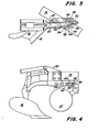
- the disc coulter 27 according to FIGS. 3 and 4 is attached much better.
- the frame part 26 (see FIGS. 1 and 2) is replaced by a holder or a frame part 34 which is connected to the main frame 14 by means of fastening elements 20.
- the frame part 34 is provided with an arc piece 36 in the region of the front end.
- the disc coulter 27 is equipped according to FIG. 3 with a support arm 38, which, as can be seen from the top view according to FIG. 3, is of an arched shape and is adapted to the arch piece 36 of the frame part 34.
- the bow piece 36 and the support arm 38 are each equipped with a slot 40 and 42 through which two bolts 44 and 46 extend, which are secured by nuts 48 and 50.
- the present invention is particularly suitable for attaching disc coulters to the frame of a plow.
- a connection it is possible to have such a connection at use their tillage equipment.
Landscapes
- Life Sciences & Earth Sciences (AREA)
- Engineering & Computer Science (AREA)
- Mechanical Engineering (AREA)
- Soil Sciences (AREA)
- Environmental Sciences (AREA)
- Soil Working Implements (AREA)
Applications Claiming Priority (2)
| Application Number | Priority Date | Filing Date | Title |
|---|---|---|---|
| US58466384A | 1984-02-29 | 1984-02-29 | |
| US584663 | 1984-02-29 |
Publications (2)
| Publication Number | Publication Date |
|---|---|
| EP0153698A2 true EP0153698A2 (fr) | 1985-09-04 |
| EP0153698A3 EP0153698A3 (fr) | 1987-06-03 |
Family
ID=24338306
Family Applications (1)
| Application Number | Title | Priority Date | Filing Date |
|---|---|---|---|
| EP85101870A Withdrawn EP0153698A3 (fr) | 1984-02-29 | 1985-02-21 | Outil pour le travail du sol |
Country Status (8)
| Country | Link |
|---|---|
| EP (1) | EP0153698A3 (fr) |
| AR (1) | AR244931A1 (fr) |
| AU (1) | AU3736785A (fr) |
| DD (1) | DD238187A5 (fr) |
| DK (1) | DK93185A (fr) |
| ES (1) | ES8602340A1 (fr) |
| FI (1) | FI850761L (fr) |
| ZA (1) | ZA851493B (fr) |
Family Cites Families (6)
| Publication number | Priority date | Publication date | Assignee | Title |
|---|---|---|---|---|
| FR712996A (fr) * | 1931-10-27 | |||
| FR469790A (fr) * | 1913-12-31 | 1914-08-10 | Stock Motorpflug Gesellschaft Mit Beschraenkter Ha | Corps de charrue réglable dans la position en hauteur sur la charrue |
| US1573988A (en) * | 1922-05-29 | 1926-02-23 | W J Burnett | Plow |
| DE483094C (de) * | 1928-11-13 | 1929-09-26 | Otto Marius Ludvigsen | Halter fuer Vorpflug, Pflugmesser und Vorderrad an Pfluegen |
| GB854761A (en) * | 1956-03-21 | 1960-11-23 | Arthur Clive Nicholson | Improvements in steerage hoes |
| US2923362A (en) * | 1957-08-12 | 1960-02-02 | Int Harvester Co | Ground wheel for implement |
-
1985
- 1985-01-07 AU AU37367/85A patent/AU3736785A/en not_active Abandoned
- 1985-02-21 EP EP85101870A patent/EP0153698A3/fr not_active Withdrawn
- 1985-02-22 AR AR85299589A patent/AR244931A1/es active
- 1985-02-25 FI FI850761A patent/FI850761L/fi not_active Application Discontinuation
- 1985-02-27 ZA ZA851493A patent/ZA851493B/xx unknown
- 1985-02-28 DD DD85273648A patent/DD238187A5/de unknown
- 1985-02-28 DK DK93185A patent/DK93185A/da not_active Application Discontinuation
- 1985-02-28 ES ES540776A patent/ES8602340A1/es not_active Expired
Also Published As
| Publication number | Publication date |
|---|---|
| ES540776A0 (es) | 1985-12-01 |
| AR244931A1 (es) | 1993-12-30 |
| DK93185A (da) | 1985-08-30 |
| FI850761A0 (fi) | 1985-02-25 |
| DK93185D0 (da) | 1985-02-28 |
| AU3736785A (en) | 1985-09-05 |
| FI850761A7 (fi) | 1985-08-30 |
| EP0153698A3 (fr) | 1987-06-03 |
| DD238187A5 (de) | 1986-08-13 |
| FI850761L (fi) | 1985-08-30 |
| ES8602340A1 (es) | 1985-12-01 |
| ZA851493B (en) | 1986-10-29 |
Similar Documents
| Publication | Publication Date | Title |
|---|---|---|
| EP0081121A1 (fr) | Dent flexible | |
| DE2926060A1 (de) | Einstellbare verbindung zwischen dem halter eines bodenbearbeitungswerkzeuges und einem fuer wenigstens zwei im abstand angeordnete halter gemeinsamen rahmen | |
| EP0153698A2 (fr) | Outil pour le travail du sol | |
| DE102009050015A1 (de) | Vorrichtung für die verstellbare Befestigung von Düngereinlegern oder Vorschälern für Pflüge | |
| EP0730816A1 (fr) | Construction de dent pour appareil agricole | |
| AT374073B (de) | Nachbearbeitungsgeraet fuer pfluege | |
| DE1026563B (de) | Vorrichtung zur Verstellung der Arbeitsbreite von Beet- oder Drehpfluegen mit Dreipunkt-Aufhaengung | |
| DE3238607A1 (de) | Pflug | |
| EP0098393B1 (fr) | Arrangement de houes tractable par un tracteur | |
| DE3504865A1 (de) | Pflug mit schnittbreiteneinstellung | |
| DE6609060U (de) | Merhschariger, an einen schlepper anbaubarer pflug, insbesondere wende- oder drehpflug. | |
| EP0170835A1 (fr) | Charrue | |
| DE434444C (de) | Untergrundlockerer | |
| DE10313179A1 (de) | Überlastsicherheitseinrichtung für Bodenbearbeitungsgeräte | |
| DE3917450A1 (de) | Von einem schlepper ziehbare anordnung von hacken | |
| DE102019103043A1 (de) | Landwirtschaftliche Bodenbearbeitungsvorrichtung | |
| DE555266C (de) | Geraet zur Entfernung des Pflanzenwuchses aus den Wasserzuleitungsrinnen der Rieselfelder | |
| AT253270B (de) | Vorrichtung zum Verstellen der Vorwerkzeuge für Pflüge | |
| AT384927B (de) | Mehrscharpflug, der an einen ackerschlepper anbaubar ist | |
| DE10313178A1 (de) | Überlastsicherheitseinrichtung für Bodenbearbeitungsgeräte | |
| DE102016111773B4 (de) | Landwirtschaftliches Bodenbearbeitungsgerät mit Bodenbearbeitungswerkzeugen und Befestigungsanordnung für ein Bodenbearbeitungswerkzeug | |
| DE10313177A1 (de) | Überlastsicherheitseinrichtung für Bodenbearbeitungsgerät | |
| DE3937820A1 (de) | Schollenplaniergeraet | |
| DE1208932B (de) | An Pfluegen zum Zerteilen und Nivellieren der Schollen angeordnete Vorrichtung | |
| AT123434B (de) | Pflug mit an dem Streichblech lösbar und in senkrechter Richtung verstellbar angelenkter Egge. |
Legal Events
| Date | Code | Title | Description |
|---|---|---|---|
| PUAI | Public reference made under article 153(3) epc to a published international application that has entered the european phase |
Free format text: ORIGINAL CODE: 0009012 |
|
| AK | Designated contracting states |
Designated state(s): DE FR GB SE |
|
| 17P | Request for examination filed |
Effective date: 19860218 |
|
| PUAL | Search report despatched |
Free format text: ORIGINAL CODE: 0009013 |
|
| AK | Designated contracting states |
Kind code of ref document: A3 Designated state(s): DE FR GB SE |
|
| STAA | Information on the status of an ep patent application or granted ep patent |
Free format text: STATUS: THE APPLICATION HAS BEEN WITHDRAWN |
|
| 18W | Application withdrawn |
Withdrawal date: 19870813 |
|
| RIN1 | Information on inventor provided before grant (corrected) |
Inventor name: LON, ROBERT GEIGER Inventor name: LOREN, GLENN ARNOLD |