EP0153767A2 - Vorrichtungen und zugehörige elektrische Schaltungen, besonders bestimmt für elektrische Zweischienen-Gleichstrom-Mini-Eisenbahnen zum Bewegen von rollendem Material ohne Polaritätsprobleme bei bestimmten Trassenführungen - Google Patents
Vorrichtungen und zugehörige elektrische Schaltungen, besonders bestimmt für elektrische Zweischienen-Gleichstrom-Mini-Eisenbahnen zum Bewegen von rollendem Material ohne Polaritätsprobleme bei bestimmten Trassenführungen Download PDFInfo
- Publication number
- EP0153767A2 EP0153767A2 EP85200003A EP85200003A EP0153767A2 EP 0153767 A2 EP0153767 A2 EP 0153767A2 EP 85200003 A EP85200003 A EP 85200003A EP 85200003 A EP85200003 A EP 85200003A EP 0153767 A2 EP0153767 A2 EP 0153767A2
- Authority
- EP
- European Patent Office
- Prior art keywords
- relay
- circuits
- supply
- apparatuses
- motor
- Prior art date
- Legal status (The legal status is an assumption and is not a legal conclusion. Google has not performed a legal analysis and makes no representation as to the accuracy of the status listed.)
- Withdrawn
Links
Images

Classifications
-
- A—HUMAN NECESSITIES
- A63—SPORTS; GAMES; AMUSEMENTS
- A63H—TOYS, e.g. TOPS, DOLLS, HOOPS OR BUILDING BLOCKS
- A63H19/00—Model railways
- A63H19/24—Electric toy railways; Systems therefor
Definitions
- the object of the present invention patent is: devices and their miniature electrical circuits with two rails operating on direct current (2R + DC) to allow the propulsion of rolling traffic without problems of polarity due to specific circuits.
- the devices are controlled and actuated by two electrical circuits: the first for supplying and transmitting signals, the second for receiving, placed on the motor rolling element.
- the basic circuit has a supply of the known type formed by a transformer-rectifier, to which is added a secondary winding 24 volt rectified, which provides a voltage, which is sent to the rails as switching pulse for the direction of rolling movement; this pulse can be sent to the secondary 0-12 volt output with voltage regulator placed on 0 volt.
- the operation can be manual by acting on the push button of the excitation of the double deflector relay at the mentioned output or automatically by connecting a pedal (a switch placed in correspondence with the rail which is closed by a wheel when the rolling element passes) or else a reed at the output and / or at the input responsible for energizing this relay.
- a timer which makes said relay inactive for X seconds, prevents a second untimely excitation of the relay placed on the motor rolling element, due to the return of the rolling element in the area where the pedal or reed is placed, causing a second switched unacceptable.
- Fig. 1 shows the electrical diagrams for selecting the electrical supply poles using diode bridges for n-phases picked up by the wheels of the rolling element by means of the rails. Under A and B are indicated the supply lines, under RU the wheels.
- Fig. 2 shows the electrical diagram of the poles by means of a diode bridge with two sockets symmetrical with respect to an axis.
- Fig. 3 shows the electrical diagram for supplying a three-axle motor rolling element with asymmetrical sockets for the selection of poles by means of diode bridges.
- Fig. 4 represents the supply diagram of a motor rolling element by means of the rails and / or the overhead line + a rail with the selection of the poles by means of diode bridges with a double mechanical diverter for the choice of the operation of the two rails and the overhead line + rail with regard to a driving rolling element; in this diagram are inserted two generators GEN A and GEN B to make electric propulsion independent of diesel or steam propulsion.
- a and B are indicated the electrical conductors corresponding to conductors A and B of fig. 6.
- Fig. 5 shows the diagram of the motor supply voltage of a rolling element with cruise voltage of 0 + 12 volts for switching the relay for the
- Fig. 6 shows the receiving circuit installed on the motor rolling element for reverse operation with nc to be considered as an additional contact of the double deflector relay of the step-by-step type, which prevents the ignition of light sources and movement forward or backward of the motor rolling element following a boost due to the switching pulse.
- a zenner diode prevents the relay from being energized in the 0-12 volt supply voltage phase.
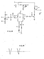
- FIG. 7 represents a circuit for supplying the model and the rolling elements of the engine comprising a transformer with three secondary ones, two of which are rectified: one with alternating current at 16 volts (the outputs of which are indicated by 2) for supplying the equipment; electro-magnetic and for the light points of the installation; a second rectified secondary (whose outputs are indicated by 1) for the supply of motors from 0-12 volt DC, on which it is also possible to send a signal at 24 volt CE for actuation of the relays; a third secondary rectified to 24 volt dc to activate the relays of the rolling elements in the zone protected by the double deflectors and an input or an output ped and reed for the automatic control of the relays of the motor rolling elements in the protected zone the electrical diagram represents the contacts in the non-operational position in phase nc, the outputs of the secondary 16 volt alternating and 0-12 volt dc; with RG the voltage regulator with contact closed in OV flow phase; with DV is indicated the
- Fig. 8 shows an electronic timer predisposed for the supply circuit illustrated in FIG. 7; its task is to prohibit the supply of 24 volts to the AUX output and to the 0-12 volt dc output for X seconds to protect the automation phases.
- Fig. 9 represents a mechanical deflector which for X contacts has X deviations; it is useful because it could be placed on motor rolling elements equipped with the devices described above to isolate the receiving circuit from the model in order to use it in the traditional way.
- Several mechanical deflectors can be used to meet the different usage requirements.
Landscapes
- Railway Tracks (AREA)
Applications Claiming Priority (2)
| Application Number | Priority Date | Filing Date | Title |
|---|---|---|---|
| IT67073/84A IT1179572B (it) | 1984-01-24 | 1984-01-24 | Apparecchi e relativi circuiti elettrici specialmente per treni elettrici in miniatura a due rotaie con corrente continua per l'esercizio dei rotabili senza problemi di polarita dovuti a determinati tracciati |
| IT6707384 | 1984-01-24 |
Publications (2)
| Publication Number | Publication Date |
|---|---|
| EP0153767A2 true EP0153767A2 (de) | 1985-09-04 |
| EP0153767A3 EP0153767A3 (en) | 1987-11-25 |
Family
ID=11299363
Family Applications (1)
| Application Number | Title | Priority Date | Filing Date |
|---|---|---|---|
| EP85200003A Withdrawn EP0153767A3 (en) | 1984-01-24 | 1985-01-03 | Apparatus and corresponding elecric circuits, especially for electric twin-rail direct-current model trains to power the rolling stock on a particular layout of the line without polarity problems |
Country Status (2)
| Country | Link |
|---|---|
| EP (1) | EP0153767A3 (de) |
| IT (1) | IT1179572B (de) |
Family Cites Families (3)
| Publication number | Priority date | Publication date | Assignee | Title |
|---|---|---|---|---|
| DE1603588A1 (de) * | 1966-06-25 | 1970-08-20 | Scheytt Dipl Ing Johannes | Schaltung zur Simultansteuerung von Wechselstrom-Modellbahnen |
| DE2124875A1 (de) * | 1971-05-19 | 1972-12-07 | Haddad, Albert G , Norfolk, Va (V St A) | Steuervorrichtung fur ein zweiglei siges elektrisches Modellfahrzeug |
| DE2654458A1 (de) * | 1976-12-01 | 1978-06-08 | Fritz Dipl Ing Kutter | Gleisplanschaltung fuer elektrische modelleisenbahnen |
-
1984
- 1984-01-24 IT IT67073/84A patent/IT1179572B/it active
-
1985
- 1985-01-03 EP EP85200003A patent/EP0153767A3/fr not_active Withdrawn
Also Published As
| Publication number | Publication date |
|---|---|
| IT8467073A0 (it) | 1984-01-24 |
| EP0153767A3 (en) | 1987-11-25 |
| IT1179572B (it) | 1987-09-16 |
Similar Documents
| Publication | Publication Date | Title |
|---|---|---|
| EP0979176B1 (de) | Bodenstromversorgung fur ein elektrisches fahrzeug mit erdverbindungsvorrichtung | |
| FR2553600A1 (fr) | Onduleur utilisable avec des charges desequilibrees et a facteur de puissance variable | |
| FR2795283A1 (fr) | Circuit d'allumage de lampe a decharge pour une pluralite de lampes | |
| EP0147280B1 (de) | Speiseverfahren und -vorrichtung für eine Last, insbesondere einen Gleichstrommotor für Doppelspannungseisenbahnlokomotiven | |
| FR2675644A1 (fr) | Circuit electrique bi-tension a signalisation de defaut perfectionnee, notamment pour vehicule automobile. | |
| EP0153767A2 (de) | Vorrichtungen und zugehörige elektrische Schaltungen, besonders bestimmt für elektrische Zweischienen-Gleichstrom-Mini-Eisenbahnen zum Bewegen von rollendem Material ohne Polaritätsprobleme bei bestimmten Trassenführungen | |
| FR2488476A1 (fr) | Circuits de commande et ensembles de commutation electrique comprenant de tels circuits | |
| EP0370896B1 (de) | Leistungs-Schalteinrichtung, insbesondere für Umrichter | |
| FR2502861A1 (fr) | Moteur a courant continu | |
| FR2729005A1 (fr) | Dispositif electrique de commande d'ouverture et de fermeture d'un interrupteur ou d'un disjoncteur | |
| FR3078029A1 (fr) | Systeme embarque de conversion de puissance electrique | |
| FR2495856A1 (fr) | Amplificateur pour servomoteur | |
| FR2489628A1 (fr) | Dispositif de commande de puissance en technique etat solide | |
| FR2693605A1 (fr) | Dispositif de commutation pour la commande de deux moteurs électriques à différentes vitesses. | |
| CA2280987C (fr) | Dispositif perfectionne d'alimentation en courant electrique de moteurs de traction de vehicules urbains ou suburbains | |
| CH651990A5 (fr) | Installation de modulation pour l'alimentation secteur d'organes de puissance. | |
| FR2998115A1 (fr) | Etage de conversion, convertisseur electrique comportant un tel etage de conversion, dispositif de conversion d'un courant alternatif en un courant continu comportant un tel convertisseur, et borne de rechargement d'une batterie electrique comportant un tel convertisseur ou dispositif de conversion | |
| FR2458959A1 (fr) | Emetteur electronique pour des systemes de telegraphie par courant continu | |
| US630927A (en) | Surface-contact railway system. | |
| US911011A (en) | Multiple-voltage system of control. | |
| FR2518477A1 (fr) | Dispositif electrique de securite commande par des trains d'impulsions generes independamment l'un de l'autre | |
| US851799A (en) | Electric traction system. | |
| US553981A (en) | Circuit-controlling device for electric-railway systems | |
| CH286316A (fr) | Poste d'itinéraires à enclenchements électriques avec blocs de route pour la commande du trafic ferroviaire. | |
| FR2674384A1 (fr) | Moteur lineaire a stator de grande longueur sans commutateur de segments. |
Legal Events
| Date | Code | Title | Description |
|---|---|---|---|
| PUAI | Public reference made under article 153(3) epc to a published international application that has entered the european phase |
Free format text: ORIGINAL CODE: 0009012 |
|
| AK | Designated contracting states |
Designated state(s): AT BE CH DE FR GB LI LU NL SE |
|
| PUAL | Search report despatched |
Free format text: ORIGINAL CODE: 0009013 |
|
| AK | Designated contracting states |
Kind code of ref document: A3 Designated state(s): AT BE CH DE FR GB LI LU NL SE |
|
| STAA | Information on the status of an ep patent application or granted ep patent |
Free format text: STATUS: THE APPLICATION IS DEEMED TO BE WITHDRAWN |
|
| 18D | Application deemed to be withdrawn |
Effective date: 19880526 |