EP0153900A2 - Commande et protection d'un servo-aiguillage avec un dispositif de télécommande ou de commande local - Google Patents
Commande et protection d'un servo-aiguillage avec un dispositif de télécommande ou de commande local Download PDFInfo
- Publication number
- EP0153900A2 EP0153900A2 EP85730006A EP85730006A EP0153900A2 EP 0153900 A2 EP0153900 A2 EP 0153900A2 EP 85730006 A EP85730006 A EP 85730006A EP 85730006 A EP85730006 A EP 85730006A EP 0153900 A2 EP0153900 A2 EP 0153900A2
- Authority
- EP
- European Patent Office
- Prior art keywords
- switch
- control
- turnout
- wsi
- protection
- Prior art date
- Legal status (The legal status is an assumption and is not a legal conclusion. Google has not performed a legal analysis and makes no representation as to the accuracy of the status listed.)
- Granted
Links
Images




Classifications
-
- B—PERFORMING OPERATIONS; TRANSPORTING
- B61—RAILWAYS
- B61L—GUIDING RAILWAY TRAFFIC; ENSURING THE SAFETY OF RAILWAY TRAFFIC
- B61L5/00—Local operating mechanisms for points or track-mounted scotch-blocks; Visible or audible signals; Local operating mechanisms for visible or audible signals
- B61L5/10—Locking mechanisms for points; Means for indicating the setting of points
- B61L5/107—Locking mechanisms for points; Means for indicating the setting of points electrical control of points position
-
- B—PERFORMING OPERATIONS; TRANSPORTING
- B61—RAILWAYS
- B61L—GUIDING RAILWAY TRAFFIC; ENSURING THE SAFETY OF RAILWAY TRAFFIC
- B61L5/00—Local operating mechanisms for points or track-mounted scotch-blocks; Visible or audible signals; Local operating mechanisms for visible or audible signals
- B61L5/06—Electric devices for operating points or scotch-blocks, e.g. using electromotive driving means
- B61L5/062—Wiring diagrams
-
- B—PERFORMING OPERATIONS; TRANSPORTING
- B61—RAILWAYS
- B61L—GUIDING RAILWAY TRAFFIC; ENSURING THE SAFETY OF RAILWAY TRAFFIC
- B61L7/00—Remote control of local operating means for points, signals, or track-mounted scotch-blocks
- B61L7/06—Remote control of local operating means for points, signals, or track-mounted scotch-blocks using electrical transmission
- B61L7/061—Remote control of local operating means for points, signals, or track-mounted scotch-blocks using electrical transmission using electromotive driving means
- B61L7/062—Wiring diagrams
-
- B—PERFORMING OPERATIONS; TRANSPORTING
- B61—RAILWAYS
- B61L—GUIDING RAILWAY TRAFFIC; ENSURING THE SAFETY OF RAILWAY TRAFFIC
- B61L7/00—Remote control of local operating means for points, signals, or track-mounted scotch-blocks
- B61L7/06—Remote control of local operating means for points, signals, or track-mounted scotch-blocks using electrical transmission
- B61L7/067—Supply for electric safety arrangements
Definitions
- the invention relates to control and protection of a switch, as defined in the preamble of claim 1.
- Points are used to adjust the travel paths of rail vehicles for local and long-distance traffic, which today are generally converted by means of electrical or hydraulic point drives. Manual adjustment is essentially only intended as a reserve for emergency operation.
- the point machines are normally controlled from control panels from a higher-level position, for example a remote control device (signal box) or a local control device nearby, using control commands.
- the modern interlockings known today generally work with point control Devices that are set up with signal relays, with four-wire cables for each point machine, which are used to control the drive and to control or report the switch positions. Disadvantages include the limited distance between the signal box and the switch (maximum 6.5 km), the high contact wear, the volume and the power consumption of the relays. In addition, and this is particularly important, there is no direct, verifiable report of the switch position taken.
- a fully electronic turnout control has already been proposed (DE-P 32 19 366), in which the aforementioned disadvantages are avoided in that the turnout drives are assigned to the turnout controls locally and these receive the control commands from the signal box via data transmission channels. From the point controls to the point drives there is a strict separation of the drive control on the one hand and the monitoring function on the other. In addition to the actual four-wire control cable, an additional six-wire end position test cable is required.
- the advantages and disadvantages are obvious. The advantages lie in the increased possible job distance up to 100 km through secure data transmission and the associated rationalization effect, and the smaller one Energy consumption (avoidance of relays).
- the contactless control of the power electronics, the targeted error diagnosis through the use of microelectronics and the now directly checkable turnout position signaling are advantageous.
- the disadvantage lies in the additional end position test cable and the retrofitting or retrofitting of existing systems that is not easily implemented.
- the object of the invention is to eliminate the shortcomings shown and to make the conventional four-wire switch drive circuits usable by adapting the microprocessor-controlled control and security concept of the aforementioned fully electronic switch control.
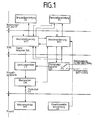
- FIG. 1 shows an overview of the functional structure of the electronic switch control. Then the switch is initiated by a remote control device FE, the actual signal box or also a local control device OE.
- the remote control device FE can act via a remote data transmission line 50 to 100 km away on a computer- or microprocessor-controlled turnout control WST, which is housed in a switchgear close to the turnout or turnout in which, for example, the local control device OE is also located.
- a computer- or microprocessor-controlled turnout control WST which is housed in a switchgear close to the turnout or turnout in which, for example, the local control device OE is also located.
- There is still an electronic one in the switch house Switch protection WSI, as well as elements belonging to the process peripherals such as a three-phase circuit breaker LS, a supervisor ÜW and a safety switch SS.
- a so-called SIRE safe computer serves as the coordinating computer for the switch control WST or switch protection WSI.
- the actual point machine WA to be controlled is a conventional four-wire point machine. It can be up to 6.5 km away from the switchgear and is connected to it via a conventional four-wire SK cable.
- a track vacancy detection device GF belonging to the turnout section complements the overview.
- the track vacancy detection device GF influences the turnout protection WSI. Effect arrows show the mutual influences.
- the invention relates to the process peripherals in the switchgear with the interacting elements three-phase circuit breaker LS, supervisor ÜW and safety switch SS in connection with the point machine WA and the point control WST and point fuse WSI.
- the point machine WA is controlled via the three-phase circuit breaker LS with the interposition of the monitor ÜW by the point controller WST, which is in operative connection with the point fuse WSI and the fuse switch SS, the latter influencing the three-phase circuit breaker LS.
- the point machine WA is connected to the supervisor ÜW by means of the usual four-wire line SK, whereby both the actuating current runs and the position and feedback take place.
- impact arrows in different directions indicate this.
- the operating principle of the switch control is three-stage and as follows: 1. Setting the switch, 2. Securing the switch, 3. Monitoring the switch.
- the turnout control WST has a control command either from the local control unit OE or from the remote control unit FE, this leads to the changeover of the turnout to the desired position. However, this is only possible if the switch is neither locked nor locked, or is not otherwise available for conversion (e.g. due to a defect). If the test is positive, the positioning job leads to the output of the actuating current to the point machine WA. Here the leaving of the end position, the turnout and the reaching of the desired end position are monitored. When the turnout has reached the end position, the actuating current is safely switched off in terms of signaling and the turnout protection requested by the turnout fuse WSI.
- the three-phase circuit breaker LS controls see FIG.
- Securing the turnout against unintentional changeover is carried out safely in terms of signaling as soon as the turnout has reached the required end position or when there is a requirement for this.
- This can be e.g. the closure order after the desired switch end position has been provided or a closure order after the associated switch section has been occupied.
- Turnout position, turnout drive WA, turnout control WST and turnout protection WSI are constantly monitored.
- the type of monitoring is different and is divided into static and dynamic monitoring. Further information is given in the following.
- the signal-safe computer functional unit for switch control - it is not the subject of the invention here - is, however, to be briefly outlined. It works on the "fail-safe" principle, i.e. a functional failure or a fault lead directly or indirectly to the safe shutdown of the computer from the process.
- the computer functional unit contains security functions for failure and fault detection as well as indirect shutdown. After failure or fault detection, depending on the cause, the fault is isolated. I.e. depending on the detected failure, only the part that cannot guarantee proper functioning is switched off safely. Is e.g. the safe function of the point machine is no longer guaranteed, it is safely switched off. The safe state that has been assumed in this way can only be left after the failure has been remedied.
- the turnout control WST itself is not safe and could try to reverse the WA drive at any time with an error.
- the switch is therefore secured in certain cases.
- a lock or lock order for one or more turnouts is carried out via the turnout protection WSI. He can be triggered by a command from the FE remote control unit or occurs automatically as soon as the turnout has reached the desired end position or the corresponding turnout section has been occupied.
- the turnout is locked regardless of a lock command if there is a fault in the turnout control or the turnout.
- the turnout fuse WSI then safely switches off the actuating current for the turnout drive WA using the fuse switch SS (positively driven relay contacts). As a rule, this switch SS is actuated in the de-energized state. In the event of a fault, switching under load is also possible.
- the switching status of the safety switch SS is continuously monitored fail-safe.
- the turnout is locked when the turnout section is occupied and remains locked as long as. the assignment is available. With the release of the switch section, the lock can be released automatically after the order has been placed.
- the turnouts can also be controlled locally. This makes work easier for the shunting staff and simplifies the signaling for the maintenance service.
- the function of the local control corresponds to that of a hand switch, which is set electrically via a control panel or directly from a vehicle.
- the circulation and the position of the turnouts is indicated either on the control panel or by a turnout signal.
- a locally operated switch can only be carried out if there is a release from the higher-level remote control device FE.
- the actuating and backup orders are changed from the remote control unit FE to the turnout control and turnout protection system WST / WSI and the messages in the opposite direction transfer. Since the transmission should also take place over larger distances, serial data transmission is provided. The data transfer rate depends on the data transfer device. Both types of telegrams (commands and messages) are byte-oriented and contain, in addition to the actual data, addressing information, security information and general control information (eg start and stop characters, start and end characters).
- the turnout control WST receives the incoming commands, determines the useful information and checks for transmission errors.
- complete message telegrams are generated from the user information from the point control and transmitted at the request of the central facility. The message telegrams are transmitted cyclically to ensure security. Command telegrams are spontaneous by nature, but can also be transmitted cyclically if required and used. At the same time, they serve as an incentive for controlled reporting:
- the three-phase circuit breaker LS is controlled by the turnout control WST via electrically isolated digital output stages DA via the control inputs R1, R2, R3, R4, R5, M. (see also Fig. 2).
- the three-phase circuit breaker LS is connected to a three-phase network 3 x 220/380 V / 50 Hz via the safety switch SS and is an actuator for the point machine WA under the supervision of a supervisor ÜW.
- the three-phase circuit breaker LS switches the three-phase current to the WA point machine without contact (wear-free).
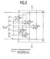
- 2 shows the basic circuit structure of the three-phase circuit breaker LS and in FIG. 3 the four-wire point machine WA actuated thereby.
- the three-phase circuit breaker LS consists of five AC switches WS1 to WS5, which are connected in the feed lines R, S, T to the windings of a point machine.
- the AC switches WS in the two phases R and S are arranged twice and work as a pole reverser. By swapping the two phases R and S using the pole reversing circuit (WS1 and WS2 or WS4 and WS5), the switch drive motor runs clockwise or counterclockwise.
- the Mp conductor is switchless.
- the three-phase circuit breaker LS is connected to the three-phase network with center conductor via the fuse switch SS to supply the actuating power to the point machine WA.
- the test voltage switch PS of the fuse switch SS is used to switch to the test voltage 60 V, 50 Hz.
- Thyristors connected in antiparallel are preferably used as the AC switch WS and the control is carried out by the switch control WST via digital outputs DA. There is strict potential isolation between the control and load circuit. The thyristors are controlled so that the load is switched immediately. The conductive state can only be removed for the duration of one or more whole AC half-waves. The three-phase circuit breaker LS is controlled via the digital output DA of the point control with DC voltage. The thyristor fires when a DC voltage is applied to the input of the respective AC switch.
- the electric turnout drive WA is controlled accordingly. It usually has a circuit as shown in FIG. 3.
- the figure is executed in signaling representation of the DB, whereby absolute cross stroke means work contact and half cross stroke means break contact.
- the required actuating force is provided by a three-phase motor 380/220 V / 50 Hz, with windings WZ, VY, UX.
- the drive sets the hotel rotation in longitudinal adjustment movements, which is transmitted to the tongues of the points via an adjusting rod.
- Two switch tester bars (not shown), each of which engage a switch tongue, are used to check whether the tongues have followed the actuating movement of the control rod and have reached the prescribed end position.
- MK3 / 3a and MK4 / 4a denote the motor contacts which cause the motor to be switched off in its end positions
- STA1, STA2, STA3 and STA4 represent contacts of a hand crank switch with which the current supply in all leads of the three-phase phases RST and the Mp conductor (terminals 1, 2, 3, 4) is interrupted if the drive should or must be operated by hand with the hand crank.
- the motor In order to limit the starting current - and to ensure a softer starting - the motor always starts with phase S against Mp and phase R against T. After the motor starts, the MK 4 / 4a motor contact and the ÜK 2 / 2a monitoring contact change their position. The center conductor Mp is switched off from phase S via contact MK 4 / 4a and the windings of all three phases are connected via contact ÜK 2 / 2a. The motor then runs at full power in star connection until the new end position is reached.
- the turnout control system WST switches off the three-phase phases via the AC switches WS1 to WSS.
- the engine is - This is monitored - and then a check of the end position of the switch is carried out.
- the two AC switches WS1 and WS2 are briefly switched on.
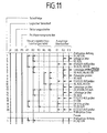
- the current monitors Ü1 to Ü3 of the monitor ÜW output a specific bit pattern in accordance with the present end position (FIGS. 8 and 9). If the target position and actual position match, the cycle of dynamic monitoring of the point machine and the point control begins (Fig. 10 and 11).
- Fig. 5 shows the fuse switch SS with actuating and test power supply in detail.
- the function of the fuse switch SS is to safely switch off the control or operating voltage from the three-phase circuit breaker LS. This prevents the turnout from rotating unintentionally.
- the fuse switch SS is part of the process periphery, is controlled by the turnout fuse WSI and also carries out all the backup tasks for the turnout. As soon as the switch has reached the end position after a changeover process and the circuit breakers have switched off the control current, the control voltage is safely separated from the three-phase circuit breaker LS by the safety switch SS.
- the safety switch SS is controlled by a safe output of the turnout fuse WSI.
- relay SS relay technology
- the control is carried out via digital outputs DA; the feedback via digital inputs.
- the fuse switch SS is also responsible for the test power supply with a secured switch, which is done via relay PS and contacts PS02, 03, 04, 15.
- the safety switch SS implements the functions of turnout locking, release of the turnout lock, locking of the turnout, unlocking of the turnout locking and securing of the turnout.
- the safety switch SS disconnects the three-phase circuit breaker LS from the three-phase network vdr in terms of signaling. This disconnection usually takes place in the de-energized state, since the three-phase circuit breaker LS has previously assumed the off state.
- the dimensioning of the fuse switch SS is designed so that, in the event of a fault in the circuit breaker LS, switching can also be carried out under load.
- the test voltage 60 V, 50 Hz
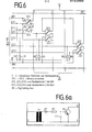
- Fig. 6 shows the schematic structure of the monitor ÜW.
- the ÜW monitor consists of six separately installed current monitors Ü1.1, Ü1.2, Ü2.1, Ü2.2, Ü3.1, Ü3.2.
- Two current monitors connected in series e.g. Ü 1.1 and Ü 1.2 - they form a current monitor, which is designated with Ü1 - are in the phase conductor R, two further current monitors Ü2.1 and Ü2.2 in the phase conductor S and the current monitors Ü3.1 and Ü3.2 in the center conductor MP switched.
- the current monitors are constructed identically, with the two current monitors connected in series each working redundantly and without feedback. See FIG. 6a, which shows such a current monitor, the input resistance is again ohmic, due to the current transformer T1 located in the input.
- the current monitor offers the possibility to control the current flow of the control current and through a potential-free transistor output when switching on and interrupting the control circuit to transmit this to the turnout protection.
- the current transformers are dimensioned on the input side in such a way that they work perfectly with both the control current of approx. 2A and the test current of approx. 0.3A.
- the three-phase circuit breaker LS controls the three-phase voltage to circulate the switch.
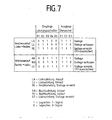
- the control currents initially flow through the current monitors Ü1, Ü2, and Ü3 and (see also FIG. 7) give a corresponding message to the outputs E1, E2, E3 (ie E1.1 and E1.2 etc.) Bit pattern 111).
- E1, E2, E3 ie E1.1 and E1.2 etc.
- Bit pattern 111 At the end of the start-up phase, after switching the appropriate MK4 / 4a motor contact and ÜK2 / 2a monitoring contacts in the point machine, no more current flows through Ü3 (Mp).
- This change of message (bit pattern 110) in the turnout control WST leads to the acknowledgment of the start-up monitoring (turnout has left its end position).
- phase T is switched off via the corresponding AC switches WS1, WS2. Then test current is sent over the phases R and S.
- Fig. 7 shows in table form the interaction of the circuit breaker LS and monitor ÜW during the actuating processes clockwise / counterclockwise rotation and the bit patterns at the outputs E1, E2, E3 of the monitor ÜW.
- bit pattern 111 according to a bit pattern 110 is not yet a criterion that the correct end position has really been reached, which is why the actuating current is always switched off and the end position checked first.
- test voltage switch PS is then actuated with the fuse switch SS and the test voltage 60 V, 50 Hz is continuously switched to the three-phase circuit breaker LS.
- FIG. 8 and 9 show state diagrams for the setting of the switch and the subsequent end position monitoring after the end position has been reached. For setting a switch from left to right (end position "right”) in Fig. 8 and for setting it from right to left (end position "left”) in Fig. 9.
- the two AC switches WSI and WS2 are controlled via the inputs R 1 and R 2 from position 13 to monitor the position.
- the test current flows - cf. 2, 6 and 3 - via phase R, switch WS1, current monitor Ü1, motor winding WZ, motor contact MK3 / 3a, via cable 4 and current monitor Ü3 back to the center conductor Mp.
- the outputs E1 and E3 of the current monitors U1 and Ü3 carry the L signal and Ü2-0 signal; Code 101 indicates the legal situation.
- the end position check for the left position is carried out similarly to FIG. 9.
- the AC switches WS1 and WS2 are in turn controlled via R1 and R2 (from item 13). However, the test current flows back through phase S, AC switch WS2, current monitor Ü2, motor winding VY, motor contact MK4 / 4a via cable wire 4 and current monitor Ü3 to the center point Mp.
Landscapes
- Engineering & Computer Science (AREA)
- Mechanical Engineering (AREA)
- Train Traffic Observation, Control, And Security (AREA)
- Selective Calling Equipment (AREA)
- Burglar Alarm Systems (AREA)
- Lock And Its Accessories (AREA)
- Organic Low-Molecular-Weight Compounds And Preparation Thereof (AREA)
- Plural Heterocyclic Compounds (AREA)
- Control Of Electric Motors In General (AREA)
- Control Of Ac Motors In General (AREA)
Priority Applications (1)
| Application Number | Priority Date | Filing Date | Title |
|---|---|---|---|
| AT85730006T ATE49167T1 (de) | 1984-02-09 | 1985-01-18 | Steuerung und sicherung einer durch eine fernstelleinrichtung (stellwerk) oder eine ortsstelleinrichtung bedienbaren weiche. |
Applications Claiming Priority (2)
| Application Number | Priority Date | Filing Date | Title |
|---|---|---|---|
| DE3404825A DE3404825C2 (de) | 1984-02-09 | 1984-02-09 | Schaltungsanordnung zur Steuerung und Sicherung einer durch eine Fernstelleinrichtung (Stellwerk) oder eine Ortsstelleinrichtung bedienbaren Weiche |
| DE3404825 | 1984-02-09 |
Publications (3)
| Publication Number | Publication Date |
|---|---|
| EP0153900A2 true EP0153900A2 (fr) | 1985-09-04 |
| EP0153900A3 EP0153900A3 (en) | 1987-09-30 |
| EP0153900B1 EP0153900B1 (fr) | 1990-01-03 |
Family
ID=6227396
Family Applications (1)
| Application Number | Title | Priority Date | Filing Date |
|---|---|---|---|
| EP85730006A Expired - Lifetime EP0153900B1 (fr) | 1984-02-09 | 1985-01-18 | Commande et protection d'un servo-aiguillage avec un dispositif de télécommande ou de commande local |
Country Status (7)
| Country | Link |
|---|---|
| EP (1) | EP0153900B1 (fr) |
| AT (1) | ATE49167T1 (fr) |
| DD (1) | DD232237A5 (fr) |
| DE (2) | DE3404825C2 (fr) |
| DK (1) | DK50485A (fr) |
| FI (1) | FI79987C (fr) |
| HU (1) | HU191165B (fr) |
Cited By (11)
| Publication number | Priority date | Publication date | Assignee | Title |
|---|---|---|---|---|
| US4986498A (en) * | 1988-05-27 | 1991-01-22 | Voest-Alpine Maschinenbau Gesellschaft M.B.H. | Device for determining the condition of railway switches or railway crossings |
| LT3361B (en) | 1988-05-27 | 1995-07-25 | Voest Alpine Eisenbahnsysteme | Recording device for condition of switches or crossings |
| EP0734932A3 (fr) * | 1995-03-28 | 1999-06-23 | Alcatel Austria Aktiengesellschaft | Dispositif de surveillance pour installations adjustables en plein air par entraínement à courant triphasé |
| EP1524166A1 (fr) * | 2003-10-17 | 2005-04-20 | Alcatel | Système de commande d'aiguillage |
| EP1593574A1 (fr) * | 2004-05-07 | 2005-11-09 | Alcatel | Système de commande d'aiguillages d'un poste d'aiguillage électronique |
| EP1607301A1 (fr) * | 2004-06-10 | 2005-12-21 | Alcatel | Procédé pour la détection de court circuits entre les conducteurs pour aiguillages |
| WO2006047971A1 (fr) * | 2004-11-02 | 2006-05-11 | Azd Praha S.R.O. | Commutateur sans contact triphase sur |
| EP2181907A1 (fr) * | 2008-10-29 | 2010-05-05 | Siemens Aktiengesellschaft | Système de diagnostic d'aiguillages |
| AT509241B1 (de) * | 2010-01-14 | 2012-03-15 | Vae Eisenbahnsysteme Gmbh | Verfahren zum überprüfen der schalter bzw. der kabel einer überwachungseinrichtung des antriebs von schienenweichen sowie vorrichtung zur durchführung dieses verfahrens |
| NL1040284A (nl) * | 2013-07-03 | 2015-01-06 | Railservice Nederland B V | Motorstroomregelaar nse-wisselsteller. |
| CN110231792A (zh) * | 2019-06-20 | 2019-09-13 | 贵州电网有限责任公司 | 一种融冰装置全功率试验控制装置和方法 |
Families Citing this family (3)
| Publication number | Priority date | Publication date | Assignee | Title |
|---|---|---|---|---|
| DE3715478A1 (de) * | 1987-05-06 | 1988-11-17 | Licentia Gmbh | Schaltungsanordnung zur ueberwachung einer weiche |
| DE9101653U1 (de) * | 1991-02-13 | 1991-05-02 | Siemens AG, 8000 München | Schaltung zum dezentralen Abschalten von Weichenantrieben bei Stellzeitüberschreitung |
| CN113650646B (zh) * | 2021-09-16 | 2022-09-27 | 杨荣兵 | 一种交流供电制式人工驾驶过分相限速保护方法 |
Family Cites Families (5)
| Publication number | Priority date | Publication date | Assignee | Title |
|---|---|---|---|---|
| DE2445618C2 (de) * | 1974-09-25 | 1986-02-27 | Standard Elektrik Lorenz Ag, 7000 Stuttgart | Schaltungsanordnung zum gemeinsamen Stellen von mindestens zwei Gleiselementen |
| DE2607328C3 (de) * | 1976-02-23 | 1979-12-06 | Siemens Ag, 1000 Berlin Und 8000 Muenchen | Steuer- und Überwachungsschaltung für Drehstrom-Weichenantriebe |
| DE3007960C2 (de) * | 1980-03-01 | 1982-08-12 | Standard Elektrik Lorenz Ag, 7000 Stuttgart | Elektronisches Stellwerk |
| DE3043661A1 (de) * | 1980-11-19 | 1982-07-08 | Siemens AG, 1000 Berlin und 8000 München | Einrichtung bei einem elektronischen stellwerk zum speisen und fernueberwachen von weichenantrieben |
| DE3219366A1 (de) * | 1982-05-19 | 1983-11-24 | Licentia Patent-Verwaltungs-Gmbh, 6000 Frankfurt | Elektronische weichensteuerung |
-
1984
- 1984-02-09 DE DE3404825A patent/DE3404825C2/de not_active Expired
-
1985
- 1985-01-18 DE DE8585730006T patent/DE3575106D1/de not_active Expired - Lifetime
- 1985-01-18 AT AT85730006T patent/ATE49167T1/de not_active IP Right Cessation
- 1985-01-18 EP EP85730006A patent/EP0153900B1/fr not_active Expired - Lifetime
- 1985-02-05 DK DK50485A patent/DK50485A/da not_active Application Discontinuation
- 1985-02-08 DD DD85273150A patent/DD232237A5/de unknown
- 1985-02-08 FI FI850534A patent/FI79987C/fi not_active IP Right Cessation
- 1985-02-08 HU HU85495A patent/HU191165B/hu not_active IP Right Cessation
Cited By (12)
| Publication number | Priority date | Publication date | Assignee | Title |
|---|---|---|---|---|
| US4986498A (en) * | 1988-05-27 | 1991-01-22 | Voest-Alpine Maschinenbau Gesellschaft M.B.H. | Device for determining the condition of railway switches or railway crossings |
| LT3361B (en) | 1988-05-27 | 1995-07-25 | Voest Alpine Eisenbahnsysteme | Recording device for condition of switches or crossings |
| MD311C2 (ro) * | 1988-05-27 | 1996-02-29 | Vae Eisenbahnsysteme Aktiengesellschaft | Dispozitiv pentru înregistrarea stării macazurilor şi a inimilor de încrucişare a lor |
| EP0734932A3 (fr) * | 1995-03-28 | 1999-06-23 | Alcatel Austria Aktiengesellschaft | Dispositif de surveillance pour installations adjustables en plein air par entraínement à courant triphasé |
| EP1524166A1 (fr) * | 2003-10-17 | 2005-04-20 | Alcatel | Système de commande d'aiguillage |
| EP1593574A1 (fr) * | 2004-05-07 | 2005-11-09 | Alcatel | Système de commande d'aiguillages d'un poste d'aiguillage électronique |
| EP1607301A1 (fr) * | 2004-06-10 | 2005-12-21 | Alcatel | Procédé pour la détection de court circuits entre les conducteurs pour aiguillages |
| WO2006047971A1 (fr) * | 2004-11-02 | 2006-05-11 | Azd Praha S.R.O. | Commutateur sans contact triphase sur |
| EP2181907A1 (fr) * | 2008-10-29 | 2010-05-05 | Siemens Aktiengesellschaft | Système de diagnostic d'aiguillages |
| AT509241B1 (de) * | 2010-01-14 | 2012-03-15 | Vae Eisenbahnsysteme Gmbh | Verfahren zum überprüfen der schalter bzw. der kabel einer überwachungseinrichtung des antriebs von schienenweichen sowie vorrichtung zur durchführung dieses verfahrens |
| NL1040284A (nl) * | 2013-07-03 | 2015-01-06 | Railservice Nederland B V | Motorstroomregelaar nse-wisselsteller. |
| CN110231792A (zh) * | 2019-06-20 | 2019-09-13 | 贵州电网有限责任公司 | 一种融冰装置全功率试验控制装置和方法 |
Also Published As
| Publication number | Publication date |
|---|---|
| HUT36410A (en) | 1985-09-30 |
| FI79987B (fi) | 1989-12-29 |
| FI79987C (fi) | 1990-04-10 |
| DE3404825C2 (de) | 1989-01-12 |
| DE3575106D1 (de) | 1990-02-08 |
| FI850534L (fi) | 1985-08-10 |
| DD232237A5 (de) | 1986-01-22 |
| EP0153900B1 (fr) | 1990-01-03 |
| FI850534A0 (fi) | 1985-02-08 |
| DK50485D0 (da) | 1985-02-05 |
| DE3404825A1 (de) | 1985-08-14 |
| HU191165B (en) | 1987-01-28 |
| ATE49167T1 (de) | 1990-01-15 |
| DK50485A (da) | 1985-08-10 |
| EP0153900A3 (en) | 1987-09-30 |
Similar Documents
| Publication | Publication Date | Title |
|---|---|---|
| DE3614979C3 (de) | Sicherheitssystem für eine Druckmaschine | |
| EP0153900B1 (fr) | Commande et protection d'un servo-aiguillage avec un dispositif de télécommande ou de commande local | |
| EP0917169B1 (fr) | Procédé de surveillance d'un sélecteur de prises | |
| DE4223435C2 (de) | Sicherheitsabschaltsystem | |
| EP0052759B1 (fr) | Dispositif dans un poste électronique d'aguillage pour l'alimentation et le télécontrôle de la commande d'aiguilles | |
| DE2607328C3 (de) | Steuer- und Überwachungsschaltung für Drehstrom-Weichenantriebe | |
| DE10023093A1 (de) | Verfahren zur Weichendiagnose und Weichendiagnoseeinrichtung | |
| EP0653333A1 (fr) | Dispositif avec au moins deux abonnés connectables par interfaces | |
| DE3638681C2 (fr) | ||
| DE69212373T2 (de) | Regelung des Kupplungs-Bremsantriebes einer Presse | |
| WO2004098976A1 (fr) | Systeme pour controler a distance des moteurs d'aiguille | |
| DE3026126C2 (de) | Einrichtung zum automatischen Betrieb und zum Schutz eines Energieversorgungsnetzes | |
| EP0894761A1 (fr) | Dispositif de fin-de-courses pour ascenseurs hydrauliques | |
| DE3029851C2 (de) | Schaltungsanordnung zur signaltechnisch sicheren Ansteuerung eines Stromverbrauchers | |
| EP0165464B1 (fr) | Circuit de fonctionnement d'un signal lumineux dans une installation de chemin de fer | |
| DE102019112713B4 (de) | Schalteranordnung und verfahren zum sicheren betrieb einer schalteranordnung | |
| DE3219366A1 (de) | Elektronische weichensteuerung | |
| DE2038031C3 (de) | Schaltungsanordnung zum Umstellen und Überwachen von Weichen mit Drehstromantrieben | |
| DE102019112712A1 (de) | Schalteranordnung mit antriebssystem und verfahren zum sicheren betrieb einer schalteranordnung | |
| DE841606C (de) | Stellwerk mit elektrischen Verschluessen, insbesondere Gleisbildstellwerk | |
| DE917373C (de) | Schaltung von Achszaehlanlagen im Eisenbahn-Sicherungswesen | |
| DE4032920C2 (de) | Verfahren und Einrichtung zur sendeseitigen Ansteuerung von Übertragungsinformation und zur signaltechnisch sicheren Prüfung von Übertragungscodes für Stellwerke, insbesondere für elektronische Stellwerke | |
| EP0397913B1 (fr) | Dispositif redresseur | |
| DE907783C (de) | Schaltung fuer elektrische Antriebe von Weichen, Gleissperren und aehnlichen Einrichtungen in elektrischen Stellwerken, insbesondere fuer Gleisbildstellwerke und aehnliche Stellwerke mit elektrischen Verschluessen | |
| DE759011C (de) | UEberwachung des Gleichlaufes von Schrittschaltern bei Fernsteuerungseinrichtungen |
Legal Events
| Date | Code | Title | Description |
|---|---|---|---|
| PUAI | Public reference made under article 153(3) epc to a published international application that has entered the european phase |
Free format text: ORIGINAL CODE: 0009012 |
|
| AK | Designated contracting states |
Designated state(s): AT BE CH DE FR GB LI NL SE |
|
| PUAL | Search report despatched |
Free format text: ORIGINAL CODE: 0009013 |
|
| AK | Designated contracting states |
Kind code of ref document: A3 Designated state(s): AT BE CH DE FR GB LI NL SE |
|
| 17P | Request for examination filed |
Effective date: 19870827 |
|
| 17Q | First examination report despatched |
Effective date: 19890221 |
|
| GRAA | (expected) grant |
Free format text: ORIGINAL CODE: 0009210 |
|
| AK | Designated contracting states |
Kind code of ref document: B1 Designated state(s): AT BE CH DE FR GB LI NL SE |
|
| REF | Corresponds to: |
Ref document number: 49167 Country of ref document: AT Date of ref document: 19900115 Kind code of ref document: T |
|
| REF | Corresponds to: |
Ref document number: 3575106 Country of ref document: DE Date of ref document: 19900208 |
|
| ET | Fr: translation filed | ||
| GBT | Gb: translation of ep patent filed (gb section 77(6)(a)/1977) | ||
| PLBE | No opposition filed within time limit |
Free format text: ORIGINAL CODE: 0009261 |
|
| STAA | Information on the status of an ep patent application or granted ep patent |
Free format text: STATUS: NO OPPOSITION FILED WITHIN TIME LIMIT |
|
| 26N | No opposition filed | ||
| PGFP | Annual fee paid to national office [announced via postgrant information from national office to epo] |
Ref country code: GB Payment date: 19911224 Year of fee payment: 8 |
|
| PGFP | Annual fee paid to national office [announced via postgrant information from national office to epo] |
Ref country code: AT Payment date: 19911231 Year of fee payment: 8 |
|
| PGFP | Annual fee paid to national office [announced via postgrant information from national office to epo] |
Ref country code: FR Payment date: 19920110 Year of fee payment: 8 |
|
| PGFP | Annual fee paid to national office [announced via postgrant information from national office to epo] |
Ref country code: BE Payment date: 19920114 Year of fee payment: 8 |
|
| PGFP | Annual fee paid to national office [announced via postgrant information from national office to epo] |
Ref country code: SE Payment date: 19920123 Year of fee payment: 8 |
|
| PGFP | Annual fee paid to national office [announced via postgrant information from national office to epo] |
Ref country code: NL Payment date: 19920131 Year of fee payment: 8 |
|
| PGFP | Annual fee paid to national office [announced via postgrant information from national office to epo] |
Ref country code: CH Payment date: 19920212 Year of fee payment: 8 |
|
| PG25 | Lapsed in a contracting state [announced via postgrant information from national office to epo] |
Ref country code: GB Effective date: 19930118 Ref country code: AT Effective date: 19930118 |
|
| PG25 | Lapsed in a contracting state [announced via postgrant information from national office to epo] |
Ref country code: SE Effective date: 19930119 |
|
| PG25 | Lapsed in a contracting state [announced via postgrant information from national office to epo] |
Ref country code: LI Effective date: 19930131 Ref country code: CH Effective date: 19930131 Ref country code: BE Effective date: 19930131 |
|
| BERE | Be: lapsed |
Owner name: LICENTIA PATENT-VERWALTUNGS G.M.B.H. Effective date: 19930131 |
|
| PG25 | Lapsed in a contracting state [announced via postgrant information from national office to epo] |
Ref country code: NL Effective date: 19930801 |
|
| GBPC | Gb: european patent ceased through non-payment of renewal fee |
Effective date: 19930118 |
|
| NLV4 | Nl: lapsed or anulled due to non-payment of the annual fee | ||
| PG25 | Lapsed in a contracting state [announced via postgrant information from national office to epo] |
Ref country code: FR Effective date: 19930930 |
|
| REG | Reference to a national code |
Ref country code: CH Ref legal event code: PL |
|
| REG | Reference to a national code |
Ref country code: FR Ref legal event code: ST |
|
| EUG | Se: european patent has lapsed |
Ref document number: 85730006.5 Effective date: 19930810 |
|
| PGFP | Annual fee paid to national office [announced via postgrant information from national office to epo] |
Ref country code: DE Payment date: 20030705 Year of fee payment: 19 |
|
| PG25 | Lapsed in a contracting state [announced via postgrant information from national office to epo] |
Ref country code: DE Free format text: LAPSE BECAUSE OF NON-PAYMENT OF DUE FEES Effective date: 20040803 |