EP0153984A2 - Procédé et dispositif pour la récupération d'hydrocarbures en C3 - Google Patents
Procédé et dispositif pour la récupération d'hydrocarbures en C3 Download PDFInfo
- Publication number
- EP0153984A2 EP0153984A2 EP84109692A EP84109692A EP0153984A2 EP 0153984 A2 EP0153984 A2 EP 0153984A2 EP 84109692 A EP84109692 A EP 84109692A EP 84109692 A EP84109692 A EP 84109692A EP 0153984 A2 EP0153984 A2 EP 0153984A2
- Authority
- EP
- European Patent Office
- Prior art keywords
- hydrocarbons
- feed stream
- fraction
- liquid
- stream
- Prior art date
- Legal status (The legal status is an assumption and is not a legal conclusion. Google has not performed a legal analysis and makes no representation as to the accuracy of the status listed.)
- Granted
Links
Images

Classifications
-
- F—MECHANICAL ENGINEERING; LIGHTING; HEATING; WEAPONS; BLASTING
- F25—REFRIGERATION OR COOLING; COMBINED HEATING AND REFRIGERATION SYSTEMS; HEAT PUMP SYSTEMS; MANUFACTURE OR STORAGE OF ICE; LIQUEFACTION SOLIDIFICATION OF GASES
- F25J—LIQUEFACTION, SOLIDIFICATION OR SEPARATION OF GASES OR GASEOUS OR LIQUEFIED GASEOUS MIXTURES BY PRESSURE AND COLD TREATMENT OR BY BRINGING THEM INTO THE SUPERCRITICAL STATE
- F25J3/00—Processes or apparatus for separating the constituents of gaseous or liquefied gaseous mixtures involving the use of liquefaction or solidification
- F25J3/02—Processes or apparatus for separating the constituents of gaseous or liquefied gaseous mixtures involving the use of liquefaction or solidification by rectification, i.e. by continuous interchange of heat and material between a vapour stream and a liquid stream
- F25J3/0228—Processes or apparatus for separating the constituents of gaseous or liquefied gaseous mixtures involving the use of liquefaction or solidification by rectification, i.e. by continuous interchange of heat and material between a vapour stream and a liquid stream characterised by the separated product stream
- F25J3/0252—Processes or apparatus for separating the constituents of gaseous or liquefied gaseous mixtures involving the use of liquefaction or solidification by rectification, i.e. by continuous interchange of heat and material between a vapour stream and a liquid stream characterised by the separated product stream separation of hydrogen
-
- C—CHEMISTRY; METALLURGY
- C07—ORGANIC CHEMISTRY
- C07C—ACYCLIC OR CARBOCYCLIC COMPOUNDS
- C07C7/00—Purification; Separation; Use of additives
- C07C7/005—Processes comprising at least two steps in series
-
- F—MECHANICAL ENGINEERING; LIGHTING; HEATING; WEAPONS; BLASTING
- F25—REFRIGERATION OR COOLING; COMBINED HEATING AND REFRIGERATION SYSTEMS; HEAT PUMP SYSTEMS; MANUFACTURE OR STORAGE OF ICE; LIQUEFACTION SOLIDIFICATION OF GASES
- F25J—LIQUEFACTION, SOLIDIFICATION OR SEPARATION OF GASES OR GASEOUS OR LIQUEFIED GASEOUS MIXTURES BY PRESSURE AND COLD TREATMENT OR BY BRINGING THEM INTO THE SUPERCRITICAL STATE
- F25J3/00—Processes or apparatus for separating the constituents of gaseous or liquefied gaseous mixtures involving the use of liquefaction or solidification
- F25J3/02—Processes or apparatus for separating the constituents of gaseous or liquefied gaseous mixtures involving the use of liquefaction or solidification by rectification, i.e. by continuous interchange of heat and material between a vapour stream and a liquid stream
- F25J3/0204—Processes or apparatus for separating the constituents of gaseous or liquefied gaseous mixtures involving the use of liquefaction or solidification by rectification, i.e. by continuous interchange of heat and material between a vapour stream and a liquid stream characterised by the feed stream
- F25J3/0219—Refinery gas, cracking gas, coke oven gas, gaseous mixtures containing aliphatic unsaturated CnHm or gaseous mixtures of undefined nature
-
- F—MECHANICAL ENGINEERING; LIGHTING; HEATING; WEAPONS; BLASTING
- F25—REFRIGERATION OR COOLING; COMBINED HEATING AND REFRIGERATION SYSTEMS; HEAT PUMP SYSTEMS; MANUFACTURE OR STORAGE OF ICE; LIQUEFACTION SOLIDIFICATION OF GASES
- F25J—LIQUEFACTION, SOLIDIFICATION OR SEPARATION OF GASES OR GASEOUS OR LIQUEFIED GASEOUS MIXTURES BY PRESSURE AND COLD TREATMENT OR BY BRINGING THEM INTO THE SUPERCRITICAL STATE
- F25J3/00—Processes or apparatus for separating the constituents of gaseous or liquefied gaseous mixtures involving the use of liquefaction or solidification
- F25J3/02—Processes or apparatus for separating the constituents of gaseous or liquefied gaseous mixtures involving the use of liquefaction or solidification by rectification, i.e. by continuous interchange of heat and material between a vapour stream and a liquid stream
- F25J3/0228—Processes or apparatus for separating the constituents of gaseous or liquefied gaseous mixtures involving the use of liquefaction or solidification by rectification, i.e. by continuous interchange of heat and material between a vapour stream and a liquid stream characterised by the separated product stream
- F25J3/0242—Processes or apparatus for separating the constituents of gaseous or liquefied gaseous mixtures involving the use of liquefaction or solidification by rectification, i.e. by continuous interchange of heat and material between a vapour stream and a liquid stream characterised by the separated product stream separation of CnHm with 3 carbon atoms or more
-
- F—MECHANICAL ENGINEERING; LIGHTING; HEATING; WEAPONS; BLASTING
- F25—REFRIGERATION OR COOLING; COMBINED HEATING AND REFRIGERATION SYSTEMS; HEAT PUMP SYSTEMS; MANUFACTURE OR STORAGE OF ICE; LIQUEFACTION SOLIDIFICATION OF GASES
- F25J—LIQUEFACTION, SOLIDIFICATION OR SEPARATION OF GASES OR GASEOUS OR LIQUEFIED GASEOUS MIXTURES BY PRESSURE AND COLD TREATMENT OR BY BRINGING THEM INTO THE SUPERCRITICAL STATE
- F25J3/00—Processes or apparatus for separating the constituents of gaseous or liquefied gaseous mixtures involving the use of liquefaction or solidification
- F25J3/02—Processes or apparatus for separating the constituents of gaseous or liquefied gaseous mixtures involving the use of liquefaction or solidification by rectification, i.e. by continuous interchange of heat and material between a vapour stream and a liquid stream
- F25J3/0228—Processes or apparatus for separating the constituents of gaseous or liquefied gaseous mixtures involving the use of liquefaction or solidification by rectification, i.e. by continuous interchange of heat and material between a vapour stream and a liquid stream characterised by the separated product stream
- F25J3/0247—Processes or apparatus for separating the constituents of gaseous or liquefied gaseous mixtures involving the use of liquefaction or solidification by rectification, i.e. by continuous interchange of heat and material between a vapour stream and a liquid stream characterised by the separated product stream separation of CnHm with 4 carbon atoms or more
-
- F—MECHANICAL ENGINEERING; LIGHTING; HEATING; WEAPONS; BLASTING
- F25—REFRIGERATION OR COOLING; COMBINED HEATING AND REFRIGERATION SYSTEMS; HEAT PUMP SYSTEMS; MANUFACTURE OR STORAGE OF ICE; LIQUEFACTION SOLIDIFICATION OF GASES
- F25J—LIQUEFACTION, SOLIDIFICATION OR SEPARATION OF GASES OR GASEOUS OR LIQUEFIED GASEOUS MIXTURES BY PRESSURE AND COLD TREATMENT OR BY BRINGING THEM INTO THE SUPERCRITICAL STATE
- F25J2200/00—Processes or apparatus using separation by rectification
- F25J2200/74—Refluxing the column with at least a part of the partially condensed overhead gas
-
- F—MECHANICAL ENGINEERING; LIGHTING; HEATING; WEAPONS; BLASTING
- F25—REFRIGERATION OR COOLING; COMBINED HEATING AND REFRIGERATION SYSTEMS; HEAT PUMP SYSTEMS; MANUFACTURE OR STORAGE OF ICE; LIQUEFACTION SOLIDIFICATION OF GASES
- F25J—LIQUEFACTION, SOLIDIFICATION OR SEPARATION OF GASES OR GASEOUS OR LIQUEFIED GASEOUS MIXTURES BY PRESSURE AND COLD TREATMENT OR BY BRINGING THEM INTO THE SUPERCRITICAL STATE
- F25J2200/00—Processes or apparatus using separation by rectification
- F25J2200/90—Details relating to column internals, e.g. structured packing, gas or liquid distribution
- F25J2200/94—Details relating to the withdrawal point
-
- F—MECHANICAL ENGINEERING; LIGHTING; HEATING; WEAPONS; BLASTING
- F25—REFRIGERATION OR COOLING; COMBINED HEATING AND REFRIGERATION SYSTEMS; HEAT PUMP SYSTEMS; MANUFACTURE OR STORAGE OF ICE; LIQUEFACTION SOLIDIFICATION OF GASES
- F25J—LIQUEFACTION, SOLIDIFICATION OR SEPARATION OF GASES OR GASEOUS OR LIQUEFIED GASEOUS MIXTURES BY PRESSURE AND COLD TREATMENT OR BY BRINGING THEM INTO THE SUPERCRITICAL STATE
- F25J2205/00—Processes or apparatus using other separation and/or other processing means
- F25J2205/02—Processes or apparatus using other separation and/or other processing means using simple phase separation in a vessel or drum
- F25J2205/04—Processes or apparatus using other separation and/or other processing means using simple phase separation in a vessel or drum in the feed line, i.e. upstream of the fractionation step
-
- F—MECHANICAL ENGINEERING; LIGHTING; HEATING; WEAPONS; BLASTING
- F25—REFRIGERATION OR COOLING; COMBINED HEATING AND REFRIGERATION SYSTEMS; HEAT PUMP SYSTEMS; MANUFACTURE OR STORAGE OF ICE; LIQUEFACTION SOLIDIFICATION OF GASES
- F25J—LIQUEFACTION, SOLIDIFICATION OR SEPARATION OF GASES OR GASEOUS OR LIQUEFIED GASEOUS MIXTURES BY PRESSURE AND COLD TREATMENT OR BY BRINGING THEM INTO THE SUPERCRITICAL STATE
- F25J2205/00—Processes or apparatus using other separation and/or other processing means
- F25J2205/50—Processes or apparatus using other separation and/or other processing means using absorption, i.e. with selective solvents or lean oil, heavier CnHm and including generally a regeneration step for the solvent or lean oil
-
- F—MECHANICAL ENGINEERING; LIGHTING; HEATING; WEAPONS; BLASTING
- F25—REFRIGERATION OR COOLING; COMBINED HEATING AND REFRIGERATION SYSTEMS; HEAT PUMP SYSTEMS; MANUFACTURE OR STORAGE OF ICE; LIQUEFACTION SOLIDIFICATION OF GASES
- F25J—LIQUEFACTION, SOLIDIFICATION OR SEPARATION OF GASES OR GASEOUS OR LIQUEFIED GASEOUS MIXTURES BY PRESSURE AND COLD TREATMENT OR BY BRINGING THEM INTO THE SUPERCRITICAL STATE
- F25J2210/00—Processes characterised by the type or other details of the feed stream
- F25J2210/12—Refinery or petrochemical off-gas
-
- F—MECHANICAL ENGINEERING; LIGHTING; HEATING; WEAPONS; BLASTING
- F25—REFRIGERATION OR COOLING; COMBINED HEATING AND REFRIGERATION SYSTEMS; HEAT PUMP SYSTEMS; MANUFACTURE OR STORAGE OF ICE; LIQUEFACTION SOLIDIFICATION OF GASES
- F25J—LIQUEFACTION, SOLIDIFICATION OR SEPARATION OF GASES OR GASEOUS OR LIQUEFIED GASEOUS MIXTURES BY PRESSURE AND COLD TREATMENT OR BY BRINGING THEM INTO THE SUPERCRITICAL STATE
- F25J2270/00—Refrigeration techniques used
- F25J2270/04—Internal refrigeration with work-producing gas expansion loop
-
- F—MECHANICAL ENGINEERING; LIGHTING; HEATING; WEAPONS; BLASTING
- F25—REFRIGERATION OR COOLING; COMBINED HEATING AND REFRIGERATION SYSTEMS; HEAT PUMP SYSTEMS; MANUFACTURE OR STORAGE OF ICE; LIQUEFACTION SOLIDIFICATION OF GASES
- F25J—LIQUEFACTION, SOLIDIFICATION OR SEPARATION OF GASES OR GASEOUS OR LIQUEFIED GASEOUS MIXTURES BY PRESSURE AND COLD TREATMENT OR BY BRINGING THEM INTO THE SUPERCRITICAL STATE
- F25J2270/00—Refrigeration techniques used
- F25J2270/60—Closed external refrigeration cycle with single component refrigerant [SCR], e.g. C1-, C2- or C3-hydrocarbons
-
- F—MECHANICAL ENGINEERING; LIGHTING; HEATING; WEAPONS; BLASTING
- F25—REFRIGERATION OR COOLING; COMBINED HEATING AND REFRIGERATION SYSTEMS; HEAT PUMP SYSTEMS; MANUFACTURE OR STORAGE OF ICE; LIQUEFACTION SOLIDIFICATION OF GASES
- F25J—LIQUEFACTION, SOLIDIFICATION OR SEPARATION OF GASES OR GASEOUS OR LIQUEFIED GASEOUS MIXTURES BY PRESSURE AND COLD TREATMENT OR BY BRINGING THEM INTO THE SUPERCRITICAL STATE
- F25J2270/00—Refrigeration techniques used
- F25J2270/90—External refrigeration, e.g. conventional closed-loop mechanical refrigeration unit using Freon or NH3, unspecified external refrigeration
-
- Y—GENERAL TAGGING OF NEW TECHNOLOGICAL DEVELOPMENTS; GENERAL TAGGING OF CROSS-SECTIONAL TECHNOLOGIES SPANNING OVER SEVERAL SECTIONS OF THE IPC; TECHNICAL SUBJECTS COVERED BY FORMER USPC CROSS-REFERENCE ART COLLECTIONS [XRACs] AND DIGESTS
- Y10—TECHNICAL SUBJECTS COVERED BY FORMER USPC
- Y10S—TECHNICAL SUBJECTS COVERED BY FORMER USPC CROSS-REFERENCE ART COLLECTIONS [XRACs] AND DIGESTS
- Y10S62/00—Refrigeration
- Y10S62/931—Recovery of hydrogen
- Y10S62/932—From natural gas
Definitions
- the invention relates to a process for the production of C 3+ hydrocarbons from a feed stream which contains hydrogen as essential constituents and C 1 to at least C 5 hydrocarbons, in which the feed stream is optionally precompressed, precleaned and cooled, a liquid and a gaseous fraction is expanded and the liquid fraction is broken down by rectification into a product stream essentially containing C 3+ hydrocarbons and a residual gas stream predominantly containing C 2 hydrocarbons.
- Such processes are used primarily to separate propane, optionally propylene and higher hydrocarbons from refinery off-gases.
- the processing of refinery waste gases has recently become economically interesting, since the market prices for LPG (C 3 / C 4 -hydrocarbon mixture) have risen, while conversely vacuum residues and heavy oil are difficult to sell. For this reason, heavy products that are difficult to market are used to cover internal fuel consumption may be burned while C3 + hydrocarbons, which are readily available for sale, are separated from the exhaust gas.
- a process of the type mentioned at the outset has already become known (Oil and Gas Journal, May 10, 1982, pages 127 to 131), in which a refinery offgas having the composition described first compresses to the required process pressure and, after separation from water, is cooled and partially condensed. The condensate is fed to a separation column in which a liquid C 3 hydrocarbon fraction and a gaseous C 2 hydrocarbon fraction are obtained. The gas fraction remaining in the partial condensation is expanded in a turboexpander and then also fed to the separation column.
- the known method has the disadvantage that the entire light fraction obtained in the phase separation is passed into the separation column after its relaxation to produce reflux liquid for rectification.
- the increase in the concentration of light components in the separation column leads to a deterioration in the rectification conditions.
- the separation column must be operated at relatively low temperatures and therefore consumes a lot of cooling capacity.
- the light fraction entered in the separation column is a two-phase mixture. This in turn means that a relaxation into the wet steam area takes place in the turboexpander and that therefore a particularly high-quality turboexpander designed for this must be used.
- the known method is therefore uneconomical.
- the invention has for its object to develop a method of the type mentioned, the back extraction of C 3+ hydrocarbons with low investment and operating costs. This object is achieved in that the gaseous fraction before expansion, the liquid fraction before rectification and the gaseous fraction after expansion are brought into heat exchange with the feed stream to be cooled.
- the cold generated during the expansion is not used as before to form reflux liquid for rectification, but rather to form condensate in the feed stream. It is therefore no longer necessary to pass the light parts from the feed stream into the separation column as before. At the same time, there is no need to generate a two-phase mixture during expansion. According to one feature of the invention, this is exploited by preheating the gas stream to be expanded in order to avoid relaxation in the wet steam region. The condensate generated by flash cooling is at a lower temperature level than that required for the subsequent rectification. According to another feature of the invention, the excess cold is used to cool the feed stream.
- the cooling takes place against external cold and cold decomposition products and the liquid fraction is warmed less strongly at least up to the temperature of the coldest external cold level and the gaseous fraction to be relaxed.
- the gaseous fraction is preferably heated no higher than the coldest external cold level.
- the liquid fraction is heated to at least the same temperature level as the gas stream obtained in the rectification.
- At least part of the gaseous fraction is used as the regeneration gas in the pre-cleaning after the expansion.
- the gas is heated and used as a purge gas for adsorbers that are used to remove water from the feed stream.
- C1 and C 2 hydrocarbons are separated from the gaseous fraction to be expanded before heating by partial condensation in order to additionally obtain high-purity hydrogen.
- the separation is particularly advantageous if the feed stream has a relatively high hydrogen content, preferably in the order of 50 to 90%.
- the amount of hydrogen is sufficient to generate the required cold during expansion, so that the hydrogen can be recovered.
- Part of the relaxed H 2 must be added to the condensed light hydrocarbons to improve their evaporation behavior.
- a further decomposition of the C 3+ hydrocarbon product in particular a separation between a C 3 / C 4 hydrocarbon mixture and C 5+ hydrocarbons, is desirable.
- the majority of the C 5+ hydrocarbons are separated off from the feed stream together with a smaller amount of C 4 hydrocarbons before the liquid and the gaseous fraction are formed.
- the separation is advantageously carried out by partial condensation at a temperature which is above the temperature at which the above-mentioned liquid and gaseous fraction are formed. Due to the previous separation, the mixture fed to the rectification is almost free of C 5+ hydrocarbons. A C 3 / C 4 hydrocarbon product stream is obtained in the subsequent rectification.
- the gaseous fraction is brought into heat exchange with the gaseous phase after its expansion, from the phase separation of the feed stream or of the stream formed after the C 5+ hydrocarbons have been separated from the feed stream.
- the phase separation device used for the phase separation acts as a reinforcing column, so that the yield increases. There are no additional operating costs.
- At least part of the work obtained during the expansion of the gaseous fraction is used to compress the feed stream and / or to recompress the expanded gaseous fraction.
- phase separation of the feed stream or of the stream formed after the C 5+ hydrocarbons have been separated off from the feed stream is carried out by washing.
- a washing liquid which contains essentially C. hydrocarbons is used for the laundry.
- washing liquid be taken from the bottom of a decomposition stage downstream of the rectification.
- a device for carrying out the method according to the invention comprises a feed line for a feed stream, in which a pre-cleaning stage and a heat exchanger with a phase separation device are arranged, the liquid collection space of which is connected to a separation column and the gas collection space of which is connected to an expansion device, and is characterized in that the connections between the phase separation device and the rectification column or the expansion device and an exhaust pipe of the expansion device are guided through the heat exchanger.
- a heat exchanger connected to the outlet of the expansion device is provided in the gas space of the phase separation device.
- a washing column is provided as the phase separation device.
- the expansion device is coupled to a compressor for the feed stream and / or to a post-compressor for the exhaust gas of the expansion device.
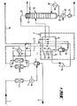
- a feed stream 1 which is, for example, a refinery offgas, such as is obtained when light crude oil components are processed to gasoline, has a composition of 10 to 90% hydrogen, C 1 to C 5 hydrocarbons, water, hydrochloric acid and, if appropriate, C 6+ hydrocarbons and hydrogen sulfide. After a necessary pre-compression, its pressure is about 15 to 30 bar, its temperature is at the cooling water temperature level (25-35 ° C) or higher.
- the feed stream is first passed through a reactor 2 filled with molecular sieves or aluminum gel, in which the hydrochloric acid is removed. The hydrochloric acid-free feed stream is then cooled to about 25-35 ° C. in a cooler 3.
- the feed stream is then fed to a pair of alternately operated dryers 6, which are filled with molecular sieves. There, the last water residues are removed from the feed stream.
- the pre-cleaned feed stream, which leaves the dryer 6, essentially contains only hydrogen, C 1 to C 5 hydrocarbons and optionally C 6+ hydrocarbons and hydrogen sulfide.
- This stream is fed to a cold box 7 shown in dashed lines, the essential components of which are a heat exchanger 8 and a phase device designed as a separator 9.
- Thief components 8 and 9 can also be individually isolated without the need for a cold box.
- the pre-cleaned feed stream 1 is exchanged in heat with a refrigerant which evaporates at one (10) or possibly two different (10,11) temperature levels (preferably -35 ° C to -50 ° C and optionally additionally 0 ° C to -20 ° C) and cooled to about -40 ° C to -80 ° C with a number of other process streams, which will be described below.
- a refrigerant which evaporates at one (10) or possibly two different (10,11) temperature levels (preferably -35 ° C to -50 ° C and optionally additionally 0 ° C to -20 ° C) and cooled to about -40 ° C to -80 ° C with a number of other process streams, which will be described below.
- part of the feed stream condenses and a two-phase mixture forms, which is fed to the separator 9.
- the separator 9 becomes a gaseous fraction 12 which contains almost all of the hydrogen contained in the feed stream and a large part of the C 1 and C 2 hydrocarbons and a liquid fraction 13 which essentially consists of C 3 hydrocarbons and a small proportion of C 1 and C 2 hydrocarbons.
- the gaseous fraction 12 is passed through part of the heat exchanger 8 and heated there in heat exchange with the feed stream 1 to a temperature which is preferably not higher than that of the refrigerant 10. It leaves the heat exchanger 8 at an intermediate point and is fed to an expansion turbine 14, in which it is expanded to about 5 to 15 bar. This relaxation can optionally be carried out in two stages with intermediate heating.
- the heating of the gas stream to be expanded in the heat exchanger 8 is selected such that no condensate formation occurs during the expansion. If necessary, the expansion turbine is coupled to a compressor for the feed stream (not shown).
- the relaxed gaseous fraction 12 the temperature of which is approximately 3 to 20 ° C. below that of the separator 9, is passed through the heat exchanger 8 and heated in heat exchange with the feed stream 1.
- a partial stream 15 of the gas stream 12 is withdrawn as fuel gas from the system, while another partial stream 16, optionally after heating in a heater 17, is used as regeneration gas for the dryers 6 operating in alternating operation. After the regeneration, the loaded regeneration gas is fed to the partial stream 15.
- the liquid fraction 13 from the separator 9 becomes flat if passed through part of the heat exchanger 8 and heats up in heat exchange with the feed stream 1 to be cooled.
- the heating preferably takes place to the temperature level of the upper (warmer) cooling circuit 11.
- the liquid fraction 13 is removed from the heat exchanger 8 at an intermediate point removed and fed to a separation column 18 in which rectification of the liquid mixture is carried out.
- the separation column 18 is operated at a pressure of approximately 10 to 20 bar, preferably 13-15 bar. It separates the C 2- and C 3+ fractions. In the process described, it is sufficient to cool the head of the separation column 18 to about -35 to -50 ° C. This is done by evaporating a foreign refrigerant in the top condenser 19, which corresponds to the refrigerant 10.
- a common refrigeration circuit is used for heat exchanger 8 and condenser 19.
- the bottom of the separation column 18 is heated by an external reboiler 20, which is heated, for example, by low pressure steam or hot water.
- a vaporous top product 21 which mainly consists of C 1 and C 2 hydrocarbons with at most 1 to 3% C 3+ hydrocarbons (residual gas stream) and a liquid bottom fraction 22, which are essentially C 3+ hydrocarbons and at most Contains 1 to 10% C 2 hydrocarbons.
- the liquid C 3+ product stream 22 is optionally subcooled in a cooler 23 and brought to the required delivery pressure by means of a pump 24.
- the gaseous fraction 21 is expanded to a pressure which is only so much above the fuel gas pressure in order to take into account the pressure losses when the adsorbers are heated and regenerated. Then it is at an intermediate according to its temperature place introduced into the heat exchanger 8 and, after heating against the feed stream T to be cooled, admixed with the relaxed gaseous fraction 12.
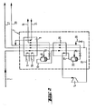
- the gaseous fraction 12 is not expanded directly from the separator 9 in the turbine 14, but is first fed to a heat exchanger 25, in which it exchanges heat with three cold flows, which are described below be cooled.
- the fraction 12 has a temperature of approximately -140 to -170 ° C. At this temperature, some of the components contained in fraction 12 condense.
- a separator 26 the two-phase mixture is separated into a gaseous phase 27, which essentially consists of hydrogen, and a liquid phase 28, which essentially contains C 1 and C 2 hydrocarbons.
- the gaseous phase 27 is passed through part of the heat exchanger 25 and heated in heat exchange with the stream 12 to be cooled before it is fed to the turbine 14.
- the gas flow 27 is expanded to about 5 to 15 bar. The preheating of the stream 27 to be expanded serves to avoid the formation of condensate during the expansion.
- the expanded gas stream 27 is passed in succession through the heat exchangers 25 and 8, whereby it heats up in heat exchange with the streams 12 and 1 to be cooled.
- the liquid phase 28 is also passed in succession through the heat exchangers 25 and 8 and heated.
- a connection line 29 is located between the lines 27 and 28 before entering the heat exchanger 25 which a certain amount of hydrogen 29 is added to the C 1 / C 2 hydrocarbon mixture 28 in order to lower the partial pressure of the hydrocarbons and to allow evaporation at low temperature.
- the method according to FIG. 2 offers the possibility of obtaining hydrogen as a product in addition to a C 3+ hydrocarbon fraction. This method makes economic sense only if the hydrogen content contained in the feed stream 1 is sufficient to generate the required cold in the turbine 14.
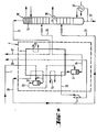
- the section of the process diagram according to FIG. 1 shown in FIG. 3 shows an embodiment of the process according to the invention in which a C 3 / C 4 hydrocarbon mixture without a C 5+ content is obtained as the product.
- the feed stream 1 is cooled in two stages, namely in two heat exchanger blocks 8a and 8b. Depending on the size of the blocks, they can also be built in a single piece. After cooling in the heat exchanger 8a against external refrigerant, whereby its higher evaporation level (11) or the lower (10) or both together (10,11) are used depending on the raw gas composition and pressure, and three streams 31, 33, which are described below. 34, the feed stream 1 has a temperature of about -10 to -35 ° C.
- the two-phase mixture is fed to a separator 30, in which the gaseous phase is separated from the liquid phase.
- the liquid phase which essentially contains C 5+ hydrocarbons and C 3 and C 4 hydrocarbons, is removed via line 31 and passed through the heat exchanger 8a, in which it is heated against the feed stream 1.
- the gaseous phase which essentially contains hydrogen and C 1 to C 4 hydrocarbons, is removed via line 32 and further cooled in the heat exchanger 8b. This creates a two-phase mixture which is fed to the separator 9.
- the gaseous phase 33 which essentially contains hydrogen and C 1 and C 2 hydrocarbons, is fed to the turbine 14, in which it is expanded, after being heated in the heat exchanger 8b. The heating in the heat exchanger 8b is carried out to such an extent that no condensation occurs during the expansion.
- the relaxed gas stream 33 is passed through the heat exchangers 8b and 8a, in which it is heated against the feed stream 1 or the stream 32.
- the current is withdrawn from the heat exchanger 8a at an intermediate point and introduced into the separation column 18.
- the rectification already described with reference to FIG. 1 takes place there with the difference that the bottom product 22 is almost free of C 5+ hydrocarbons.
- the method according to FIG. 3 has the disadvantage, however, that when C S + hydrocarbons are separated off in the separator 30, a not inconsiderable part of C 3 and C 4 hydrocarbons are separated off with the condensate. A higher yield of C 3 and C 4 hydrocarbons enables an embodiment of the method which is described with reference to FIG. 4.
- the dried feed stream 1 becomes analogous to that in FIG 3 only cooled down to a temperature at which the C 5+ hydrocarbons condense.
- the two-phase mixture removed from the heat exchanger 8 at an intermediate point is fed to the separator 30, in which phase separation is carried out.
- the gaseous phase 32 is returned to the heat exchanger 8 at an intermediate point and removed from it at the cold end.
- the liquid phase 31, on the other hand, is supplied to the separation column 18 after heating in part of the heat exchanger 8. The feed takes place below the point at which the fraction 34 is introduced from the separator 9 into the separation column 18.
- the separation column 18 has a larger number of trays than the separation column in the method according to FIG. 3. It has a removal line 35 between the two feeds of the streams 31 and 34. In this area there is a maximum concentration of C 3 and C 4 hydrocarbons.
- a heat exchanger 36 is provided in the gas space of the separator 9. which is connected to the exhaust side of the turbine 14. Through the heat exchanger 36, the separator 9 works like a reinforcing column, so that the yield in the phase separation increases.
- the heat exchanger 36 may ER both in the V direction drive of Figure 1, in which the feed stream is introduced into the separator 9 1, as well as in the process procedure according to Figure 3 or Figure 4, in which an after separation of the C 5+ hydrocarbons stream 32 formed from the feed stream is introduced into the separator 9, can be provided.
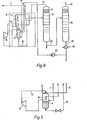
- the phase separation of the feed stream 1 is carried out in a washing column 37.
- the gaseous fraction 12 withdrawing overhead is expanded in the turbine 14 to perform work, the relaxed gas flow is used in a heat exchanger 36 for cooling the head of the washing column 37.
- the liquid bottom fraction from the washing column 37 is fed via line 13 to the rectification column 18.
- the C 3+ fraction 22, which is removed from the bottom of the rectification column 18, is fed to a further rectification column 38, in which a separation into a C 3 / C 4 fraction, which is removed via line 39 from the top of the rectification column 38 and a C 5+ fraction, which is withdrawn via a line 40 from the bottom of the rectification column 38, takes place.
- the C 5 fraction is cooled in a cooler 41 and fed as a return to the washing column 37 by means of a pump 42.
Landscapes
- Engineering & Computer Science (AREA)
- Physics & Mathematics (AREA)
- Mechanical Engineering (AREA)
- Thermal Sciences (AREA)
- General Engineering & Computer Science (AREA)
- Chemical & Material Sciences (AREA)
- Organic Chemistry (AREA)
- Analytical Chemistry (AREA)
- Oil, Petroleum & Natural Gas (AREA)
- Water Supply & Treatment (AREA)
- Production Of Liquid Hydrocarbon Mixture For Refining Petroleum (AREA)
- Separation By Low-Temperature Treatments (AREA)
Applications Claiming Priority (2)
| Application Number | Priority Date | Filing Date | Title |
|---|---|---|---|
| DE19843408760 DE3408760A1 (de) | 1984-03-09 | 1984-03-09 | Verfahren zur gewinnung von c(pfeil abwaerts)3(pfeil abwaerts)(pfeil abwaerts)+(pfeil abwaerts)-kohlenwasserstoffen |
| DE3408760 | 1984-03-09 |
Publications (3)
| Publication Number | Publication Date |
|---|---|
| EP0153984A2 true EP0153984A2 (fr) | 1985-09-11 |
| EP0153984A3 EP0153984A3 (en) | 1986-01-02 |
| EP0153984B1 EP0153984B1 (fr) | 1988-03-30 |
Family
ID=6230068
Family Applications (1)
| Application Number | Title | Priority Date | Filing Date |
|---|---|---|---|
| EP84109692A Expired EP0153984B1 (fr) | 1984-03-09 | 1984-08-14 | Procédé et dispositif pour la récupération d'hydrocarbures en C3 |
Country Status (5)
| Country | Link |
|---|---|
| US (1) | US4608068A (fr) |
| EP (1) | EP0153984B1 (fr) |
| AU (1) | AU576351B2 (fr) |
| CA (1) | CA1249215A (fr) |
| DE (2) | DE3408760A1 (fr) |
Cited By (3)
| Publication number | Priority date | Publication date | Assignee | Title |
|---|---|---|---|---|
| WO1993004327A1 (fr) * | 1991-08-19 | 1993-03-04 | Linde Aktiengesellschaft | Procede de separation d'hydrocarbures a temperature d'ebullition superieure dans un melange gazeux |
| WO1994008923A1 (fr) * | 1992-10-16 | 1994-04-28 | Linde Aktiengesellschaft | Procede de separation d'un courant de charge constitue essentiellement d'hydrogene, de methane et d'hydrocarbures c3/c¿4? |
| CN109224752A (zh) * | 2018-08-27 | 2019-01-18 | 珠海格力电器股份有限公司 | 一种脱脂油回收装置和控制方法 |
Families Citing this family (19)
| Publication number | Priority date | Publication date | Assignee | Title |
|---|---|---|---|---|
| DE3445995A1 (de) * | 1984-12-17 | 1986-06-19 | Linde Ag | Verfahren zur gewinnung von c(pfeil abwaerts)2(pfeil abwaerts)(pfeil abwaerts)+(pfeil abwaerts)- oder von c(pfeil abwaerts)3(pfeil abwaerts)(pfeil abwaerts)+(pfeil abwaerts)-kohlenwasserstoffen |
| DE3445961A1 (de) * | 1984-12-17 | 1986-06-26 | Linde Ag, 6200 Wiesbaden | Verfahren zur abtrennung von c(pfeil abwaerts)3(pfeil abwaerts)(pfeil abwaerts)+(pfeil abwaerts)-kohlenwasserstoffen aus einem gasstrom |
| NO166934C (no) * | 1984-12-17 | 1991-09-18 | Linde Ag | Fremgangsmaate for utskillelse av c2+-, c3+- eller c4+ hydrocarboner fra en gasstroem som inneholder lette hydrocarboner og eventuelt bestanddeler med lavere kokepunkt enn methan |
| DE3511636A1 (de) * | 1984-12-17 | 1986-07-10 | Linde Ag, 6200 Wiesbaden | Verfahren zur gewinnung von c(pfeil abwaerts)2(pfeil abwaerts)(pfeil abwaerts)+(pfeil abwaerts)- oder von c(pfeil abwaerts)3(pfeil abwaerts)(pfeil abwaerts)+(pfeil abwaerts)-kohlenwasserstoffen |
| DE3445994A1 (de) * | 1984-12-17 | 1986-06-19 | Linde Ag | Verfahren zur gewinnung von c(pfeil abwaerts)2(pfeil abwaerts)(pfeil abwaerts)+(pfeil abwaerts)- oder von c(pfeil abwaerts)3(pfeil abwaerts)(pfeil abwaerts)+(pfeil abwaerts)-kohlenwasserstoffen |
| DE3544855A1 (de) * | 1985-12-18 | 1987-06-19 | Linde Ag | Verfahren zur abtrennung von c(pfeil abwaerts)5(pfeil abwaerts)(pfeil abwaerts)+(pfeil abwaerts)-kohlenwasserstoffen aus einem gasstrom |
| US4749393A (en) * | 1987-09-18 | 1988-06-07 | Air Products And Chemicals, Inc. | Process for the recovery of hydrogen/heavy hydrocarbons from hydrogen-lean feed gases |
| US5035732A (en) * | 1990-01-04 | 1991-07-30 | Stone & Webster Engineering Corporation | Cryogenic separation of gaseous mixtures |
| US5287703A (en) * | 1991-08-16 | 1994-02-22 | Air Products And Chemicals, Inc. | Process for the recovery of C2 + or C3 + hydrocarbons |
| US5561988A (en) * | 1995-10-27 | 1996-10-08 | Advanced Extraction Technologies, Inc. | Retrofit unit for upgrading natural gas refrigeraition plants |
| PL188211B1 (pl) * | 1995-10-27 | 2004-12-31 | Advanced Extraction Technol | Instalacja do obróbki gazu ziemnego, sposób i jednostka modernizująca do instalacji gazu ziemnego |
| TW366409B (en) * | 1997-07-01 | 1999-08-11 | Exxon Production Research Co | Process for liquefying a natural gas stream containing at least one freezable component |
| US6343487B1 (en) | 2001-02-22 | 2002-02-05 | Stone & Webster, Inc. | Advanced heat integrated rectifier system |
| US6931889B1 (en) * | 2002-04-19 | 2005-08-23 | Abb Lummus Global, Randall Gas Technologies | Cryogenic process for increased recovery of hydrogen |
| US6560989B1 (en) * | 2002-06-07 | 2003-05-13 | Air Products And Chemicals, Inc. | Separation of hydrogen-hydrocarbon gas mixtures using closed-loop gas expander refrigeration |
| DE102005021530A1 (de) * | 2005-05-10 | 2006-11-23 | Linde Ag | Verfahren und Vorrichtung zur Gewinnung von Produkten aus Synthesegas |
| DE102005025651A1 (de) * | 2005-06-03 | 2006-12-07 | Linde Ag | Verfahren und Vorrichtung zur Gewinnung von Produkten aus Synthesegas |
| FR2907025B1 (fr) * | 2006-10-11 | 2009-05-08 | Inst Francais Du Petrole | Procede de capture du co2 avec integration thermique du regenerateur. |
| RU2748365C1 (ru) * | 2020-10-08 | 2021-05-24 | Общество С Ограниченной Ответственностью "Пегаз Инжиниринг" | Установка извлечения углеводородов c3+ из природного газа низкотемпературной конденсацией |
Family Cites Families (2)
| Publication number | Priority date | Publication date | Assignee | Title |
|---|---|---|---|---|
| DE2843982A1 (de) * | 1978-10-09 | 1980-04-24 | Linde Ag | Verfahren zum zerlegen eines gasgemisches |
| DE3215829A1 (de) * | 1982-04-28 | 1983-11-03 | Linde Ag, 6200 Wiesbaden | Verfahren zur gewinnung von kohlenmonoxid |
-
1984
- 1984-03-09 DE DE19843408760 patent/DE3408760A1/de not_active Withdrawn
- 1984-08-14 DE DE8484109692T patent/DE3470156D1/de not_active Expired
- 1984-08-14 EP EP84109692A patent/EP0153984B1/fr not_active Expired
-
1985
- 1985-03-08 US US06/709,742 patent/US4608068A/en not_active Expired - Fee Related
- 1985-03-08 CA CA000476136A patent/CA1249215A/fr not_active Expired
- 1985-03-11 AU AU39715/85A patent/AU576351B2/en not_active Ceased
Cited By (3)
| Publication number | Priority date | Publication date | Assignee | Title |
|---|---|---|---|---|
| WO1993004327A1 (fr) * | 1991-08-19 | 1993-03-04 | Linde Aktiengesellschaft | Procede de separation d'hydrocarbures a temperature d'ebullition superieure dans un melange gazeux |
| WO1994008923A1 (fr) * | 1992-10-16 | 1994-04-28 | Linde Aktiengesellschaft | Procede de separation d'un courant de charge constitue essentiellement d'hydrogene, de methane et d'hydrocarbures c3/c¿4? |
| CN109224752A (zh) * | 2018-08-27 | 2019-01-18 | 珠海格力电器股份有限公司 | 一种脱脂油回收装置和控制方法 |
Also Published As
| Publication number | Publication date |
|---|---|
| EP0153984A3 (en) | 1986-01-02 |
| CA1249215A (fr) | 1989-01-24 |
| DE3408760A1 (de) | 1985-09-12 |
| EP0153984B1 (fr) | 1988-03-30 |
| AU3971585A (en) | 1985-09-12 |
| AU576351B2 (en) | 1988-08-25 |
| DE3470156D1 (en) | 1988-05-05 |
| US4608068A (en) | 1986-08-26 |
Similar Documents
| Publication | Publication Date | Title |
|---|---|---|
| EP0153984B1 (fr) | Procédé et dispositif pour la récupération d'hydrocarbures en C3 | |
| EP0017174B1 (fr) | Procédé pour séparer un mélange gazeux | |
| DE69413918T2 (de) | Tieftemperaturzerlegung von Luft | |
| DE3706733C2 (fr) | ||
| DE69509836T2 (de) | Verfahren und Vorrichtung zur Lufttrennung | |
| DE68901854T2 (de) | Ethanrueckgewinnungsverfahren. | |
| DE69619062T2 (de) | Lufttrennungsverfahren und Vorrichtung zur Herstellung von Stickstoff | |
| EP0100923B1 (fr) | Procédé et dispositif pour séparer un mélange de gaz | |
| EP0185253B1 (fr) | Procédé et appareil pour la récupération d'hydrocarbures en C2+ ou C3+ | |
| DE2558903A1 (de) | Behandlung von naturgas | |
| DE69905426T2 (de) | Verfahren zur Herstellung von Kohlenmonoxid | |
| EP0955509A1 (fr) | Procédé et appareil pour la production d'oxygène à haute pureté | |
| DE69909143T2 (de) | Trennung von Kohlenstoffmonoxid aus stickstoffverschmutzten, Wasserstoff und Methan enthaltenden Gasgemischen | |
| DE69614815T2 (de) | Verfahren und Vorrichtung zur Stickstofferzeugung | |
| DE69614950T2 (de) | Verfahren und vorrichtung zur erzeugung von hochreinem stickstoff | |
| DE69915872T2 (de) | Verfahren zur trennung von kohlenwasserstoffen bei niedriger temperatur | |
| EP0010223B1 (fr) | Procédé pour la décomposition d'un mélange gazeux | |
| DE3307181C2 (fr) | ||
| DE69520134T2 (de) | Verfahren und Vorrichtung zum Verdichten eines zu destillierenden Gasgemisches und zum Entspannen wenigstens eines Gasstromes | |
| DE3822175A1 (de) | Verfahren zum entfernen von stickstoff aus stickstoffhaltigem erdgas | |
| EP0185202B1 (fr) | Procédé de récupération d'hydrocarbures en C2+, C3+ ou C4+ | |
| WO2017144151A1 (fr) | Procédé et dispositif de décomposition cryogénique d'un gaz de synthèse | |
| DE3227477C2 (de) | Tieftemperatur-Verfahren zur Entfernung von sauren Gasen aus natürlichen oder synthetischen Gasgemischen | |
| DE3227465C2 (de) | Tieftemperatur-Verfahren zur getrennten Entfernung von sauren Gasen aus natürlichen oder synthetischen Gasgemischen | |
| DE3244143A1 (de) | Verfahren zur gaszerlegung |
Legal Events
| Date | Code | Title | Description |
|---|---|---|---|
| PUAI | Public reference made under article 153(3) epc to a published international application that has entered the european phase |
Free format text: ORIGINAL CODE: 0009012 |
|
| AK | Designated contracting states |
Designated state(s): CH DE FR GB IT LI NL |
|
| PUAL | Search report despatched |
Free format text: ORIGINAL CODE: 0009013 |
|
| AK | Designated contracting states |
Designated state(s): CH DE FR GB IT LI NL |
|
| 17P | Request for examination filed |
Effective date: 19860116 |
|
| 17Q | First examination report despatched |
Effective date: 19860829 |
|
| GRAA | (expected) grant |
Free format text: ORIGINAL CODE: 0009210 |
|
| AK | Designated contracting states |
Kind code of ref document: B1 Designated state(s): CH DE FR GB IT LI NL |
|
| REF | Corresponds to: |
Ref document number: 3470156 Country of ref document: DE Date of ref document: 19880505 |
|
| ITF | It: translation for a ep patent filed | ||
| ET | Fr: translation filed | ||
| GBT | Gb: translation of ep patent filed (gb section 77(6)(a)/1977) | ||
| PLBI | Opposition filed |
Free format text: ORIGINAL CODE: 0009260 |
|
| 26 | Opposition filed |
Opponent name: COMBUSTION ENGINEERING, INC. Effective date: 19881230 |
|
| NLR1 | Nl: opposition has been filed with the epo |
Opponent name: COMBUSTION ENGINEERING, INC. |
|
| PLBN | Opposition rejected |
Free format text: ORIGINAL CODE: 0009273 |
|
| STAA | Information on the status of an ep patent application or granted ep patent |
Free format text: STATUS: OPPOSITION REJECTED |
|
| 27O | Opposition rejected |
Effective date: 19910322 |
|
| ITTA | It: last paid annual fee | ||
| NLR2 | Nl: decision of opposition | ||
| PGFP | Annual fee paid to national office [announced via postgrant information from national office to epo] |
Ref country code: GB Payment date: 19930730 Year of fee payment: 10 |
|
| PGFP | Annual fee paid to national office [announced via postgrant information from national office to epo] |
Ref country code: NL Payment date: 19930831 Year of fee payment: 10 |
|
| PG25 | Lapsed in a contracting state [announced via postgrant information from national office to epo] |
Ref country code: GB Effective date: 19940814 |
|
| PGFP | Annual fee paid to national office [announced via postgrant information from national office to epo] |
Ref country code: CH Payment date: 19940815 Year of fee payment: 11 |
|
| PG25 | Lapsed in a contracting state [announced via postgrant information from national office to epo] |
Ref country code: NL Effective date: 19950301 |
|
| GBPC | Gb: european patent ceased through non-payment of renewal fee |
Effective date: 19940814 |
|
| NLV4 | Nl: lapsed or anulled due to non-payment of the annual fee | ||
| PGFP | Annual fee paid to national office [announced via postgrant information from national office to epo] |
Ref country code: FR Payment date: 19950809 Year of fee payment: 12 |
|
| PG25 | Lapsed in a contracting state [announced via postgrant information from national office to epo] |
Ref country code: LI Effective date: 19950831 Ref country code: CH Effective date: 19950831 |
|
| PGFP | Annual fee paid to national office [announced via postgrant information from national office to epo] |
Ref country code: DE Payment date: 19950926 Year of fee payment: 12 |
|
| REG | Reference to a national code |
Ref country code: CH Ref legal event code: PL |
|
| PG25 | Lapsed in a contracting state [announced via postgrant information from national office to epo] |
Ref country code: FR Effective date: 19970430 |
|
| PG25 | Lapsed in a contracting state [announced via postgrant information from national office to epo] |
Ref country code: DE Effective date: 19970501 |
|
| REG | Reference to a national code |
Ref country code: FR Ref legal event code: ST |