EP0154148A1 - Rotor de tissage pour un métier à tisser multiphasé à foule linéaire - Google Patents
Rotor de tissage pour un métier à tisser multiphasé à foule linéaire Download PDFInfo
- Publication number
- EP0154148A1 EP0154148A1 EP85100805A EP85100805A EP0154148A1 EP 0154148 A1 EP0154148 A1 EP 0154148A1 EP 85100805 A EP85100805 A EP 85100805A EP 85100805 A EP85100805 A EP 85100805A EP 0154148 A1 EP0154148 A1 EP 0154148A1
- Authority
- EP
- European Patent Office
- Prior art keywords
- weaving
- weaving rotor
- control device
- rotor
- warp threads
- Prior art date
- Legal status (The legal status is an assumption and is not a legal conclusion. Google has not performed a legal analysis and makes no representation as to the accuracy of the status listed.)
- Granted
Links
- 238000009941 weaving Methods 0.000 title claims abstract description 36
- 239000004744 fabric Substances 0.000 claims description 4
- 238000011161 development Methods 0.000 description 1
- 230000018109 developmental process Effects 0.000 description 1
- 238000003780 insertion Methods 0.000 description 1
- 230000037431 insertion Effects 0.000 description 1
- 210000000056 organ Anatomy 0.000 description 1
Images

Classifications
-
- D—TEXTILES; PAPER
- D03—WEAVING
- D03D—WOVEN FABRICS; METHODS OF WEAVING; LOOMS
- D03D41/00—Looms not otherwise provided for, e.g. for weaving chenille yarn; Details peculiar to these looms
- D03D41/005—Linear-shed multiphase looms
Definitions
- the invention relates to a weaving rotor for row shed looms with an associated control device for controlling the warp threads in the weaving rotor.
- control device In a known device of this type (EU-PS 12 253), the control device consists of control rods which can be moved back and forth in the longitudinal direction and run parallel to the weaving rotor and which control the warp threads in the weaving rotor, so that its shed-forming organs bring the warp threads according to the fabric pattern into the high or low position .
- the control rods are as close as possible, e.g. at a distance of 1 - 2 mm to the rotor.
- the disadvantage of this measure is that e.g. in the event of warp thread breakage, the handling of the warp threads is very difficult since they have become practically inaccessible in this area.
- the invention has for its object to provide a control device of the type defined in which the warp threads can be made easily accessible if necessary despite the proximity of the control device to the weaving rotor.
- This object is achieved according to the invention by the feature specified in the characterizing part of claim 1.
- the UN Teran p rüche concern advantageous developments.
- control device can be distanced from the weaving rotor, so that sufficient distance can be created between the control device and the weaving rotor to correct errors and the warp threads in front of the weaving rotor can be accessed.
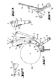
- a control device 1 for inserting the warp threads into the weaving rotor is mounted in front of a weaving rotor of a row shed weaving machine (not shown).
- the control device 1 which extends over the weaving width of the machine, has a number of control rods 2, which are provided over their length with thread eyelets 3 for guiding the warp threads 4.
- the control rods 2 are guided in guide plates 5 of a frame 6.
- the frame 6 consists of two rods 7 and 8, which are connected by side rods 9 and 10.
- the guide plates 5 point for each tax rod 2 has a recess 11.
- the frame 6 is carried by a number of quarter-circular levers 12 which are clamped on the one hand on the rod 8 and on the other hand on a shaft 13.
- the shaft 13 is in turn rotatable in supports 14 on the weaving machine.
- the levers 12 are each provided with a pin 15 which is inserted in a recess 16 of a locking lever 17.
- the locking levers 17 are clamped on an axis 18.
- an adjusting lever 19 is also attached.
- control rods 2 On the side of a gearbox 20 of the weaving machine, the control rods 2 are provided with a guide piece 21, in the groove 22 of which an underside 23 of a thrust plate 24 extends. Each push plate 24 is fastened on a push rod 25 which extends into the gearbox 20 and is guided there on a control disk. The control rods 2 are moved back and forth by the control disks in accordance with the fabric pattern, so that the warp threads 4 are driven into the weaving rotor in accordance with the fabric pattern.
- the actuating lever 19 is pressed backwards so that the frame 6 is pivoted away from the weaving rotor over a distance a of around 30 mm and between the control device and the warp threads running through the weaving rotor become accessible.
- the guide pieces 21 of the control rods 2 slide along the thrust plates 24 and therefore remain in engagement therewith, so that the control rods and thus the warp threads maintain their position with respect to the weaving rotor. Since the control rods 2 pivot downwards, the warp threads remain on the shed forming elements of the weaving rotor.
- the Frame 6 rotated back into the operating position by means of the adjusting lever 19.
- the pins 15 of the lever 12 snap into the recesses 16 of the locking lever 17 and lock the frame 6 in the operating position.
- the securing lever 17 located next to the adjusting lever 19 is provided with a pin 31 which is pressed by the adjusting lever.
- the drive of the control rods need not be designed as shown and described. Other connections between the weaving machine and the control device are conceivable. It is even conceivable to mount the drive on the control device itself, so that both are swung out together.
- control device is described as pivotable here, it can of course also be arranged to be displaceable with respect to the weaving rotor, e.g. by being attached to supports guided in holes in the weaving machine.
Landscapes
- Engineering & Computer Science (AREA)
- Textile Engineering (AREA)
- Looms (AREA)
Applications Claiming Priority (2)
| Application Number | Priority Date | Filing Date | Title |
|---|---|---|---|
| DE19843406129 DE3406129C1 (de) | 1984-02-21 | 1984-02-21 | Webrotor fuer Reihenfachwebmaschinen |
| DE3406129 | 1984-02-21 |
Publications (2)
| Publication Number | Publication Date |
|---|---|
| EP0154148A1 true EP0154148A1 (fr) | 1985-09-11 |
| EP0154148B1 EP0154148B1 (fr) | 1988-09-21 |
Family
ID=6228307
Family Applications (1)
| Application Number | Title | Priority Date | Filing Date |
|---|---|---|---|
| EP19850100805 Expired EP0154148B1 (fr) | 1984-02-21 | 1985-01-26 | Rotor de tissage pour un métier à tisser multiphasé à foule linéaire |
Country Status (4)
| Country | Link |
|---|---|
| EP (1) | EP0154148B1 (fr) |
| DD (1) | DD232318A5 (fr) |
| DE (1) | DE3406129C1 (fr) |
| SU (1) | SU1449018A3 (fr) |
Cited By (2)
| Publication number | Priority date | Publication date | Assignee | Title |
|---|---|---|---|---|
| EP0612875A1 (fr) * | 1993-02-26 | 1994-08-31 | Sulzer RàTi Ag | Dispositif pour la production de dessins dans un métier à tisser multiphase |
| US7132443B2 (en) | 2001-06-27 | 2006-11-07 | Smithklinebeecham Corporation | Fluoropyrrolidines as dipeptidyl peptidase inhibitors |
Citations (3)
| Publication number | Priority date | Publication date | Assignee | Title |
|---|---|---|---|---|
| EP0012253A1 (fr) * | 1978-12-07 | 1980-06-25 | Maschinenfabrik Sulzer-Rüti Ag | Métier à tisser multiphasé à foule linéaire avec un rotor de tissage |
| EP0013321A1 (fr) * | 1978-12-07 | 1980-07-23 | Maschinenfabrik Sulzer-Rüti Ag | Métier à tisser multiphasé à foule linéaire avec un rotor de tissage |
| EP0093078A2 (fr) * | 1982-04-28 | 1983-11-02 | Maschinenfabrik Sulzer-Rüti Ag | Métier à tisser multiphasé à foule linéaire avec un rotor de tissage |
-
1984
- 1984-02-21 DE DE19843406129 patent/DE3406129C1/de not_active Expired
-
1985
- 1985-01-26 EP EP19850100805 patent/EP0154148B1/fr not_active Expired
- 1985-02-19 DD DD27337485A patent/DD232318A5/de not_active IP Right Cessation
- 1985-02-20 SU SU853858822A patent/SU1449018A3/ru active
Patent Citations (3)
| Publication number | Priority date | Publication date | Assignee | Title |
|---|---|---|---|---|
| EP0012253A1 (fr) * | 1978-12-07 | 1980-06-25 | Maschinenfabrik Sulzer-Rüti Ag | Métier à tisser multiphasé à foule linéaire avec un rotor de tissage |
| EP0013321A1 (fr) * | 1978-12-07 | 1980-07-23 | Maschinenfabrik Sulzer-Rüti Ag | Métier à tisser multiphasé à foule linéaire avec un rotor de tissage |
| EP0093078A2 (fr) * | 1982-04-28 | 1983-11-02 | Maschinenfabrik Sulzer-Rüti Ag | Métier à tisser multiphasé à foule linéaire avec un rotor de tissage |
Cited By (3)
| Publication number | Priority date | Publication date | Assignee | Title |
|---|---|---|---|---|
| EP0612875A1 (fr) * | 1993-02-26 | 1994-08-31 | Sulzer RàTi Ag | Dispositif pour la production de dessins dans un métier à tisser multiphase |
| US5441085A (en) * | 1993-02-26 | 1995-08-15 | Sulzer Rueti Ag | Warp thread insertion device for series-shed looms |
| US7132443B2 (en) | 2001-06-27 | 2006-11-07 | Smithklinebeecham Corporation | Fluoropyrrolidines as dipeptidyl peptidase inhibitors |
Also Published As
| Publication number | Publication date |
|---|---|
| DD232318A5 (de) | 1986-01-22 |
| EP0154148B1 (fr) | 1988-09-21 |
| SU1449018A3 (ru) | 1988-12-30 |
| DE3406129C1 (de) | 1985-07-25 |
Similar Documents
| Publication | Publication Date | Title |
|---|---|---|
| DE1963208B2 (de) | Wellenwebmaschine | |
| EP0154148B1 (fr) | Rotor de tissage pour un métier à tisser multiphasé à foule linéaire | |
| EP0576854B1 (fr) | Métier à tisser à griffes | |
| EP0214322B1 (fr) | Dispositif pour la formation du pas de gaze dans les métiers à tisser | |
| EP0199880A1 (fr) | Dispositif d'insertion de trame pour métier à tisser, plus particulièrement un métier à tisser à navette à griffe | |
| DE2949765C2 (de) | Schützenlose Webmaschine | |
| EP0162175A1 (fr) | Dispositif d'introduction du fil de trame dans les métiers à jet d'air | |
| DE2329302A1 (de) | Vorrichtung zur gewebekantenbildung an webmaschinen | |
| EP0535203B1 (fr) | Metier a tisser circulaire | |
| DE2655269C2 (de) | Nadelbarre für Kettenwirkmaschine | |
| DE641751C (de) | Offenfach-Schaftmaschine | |
| DE2244984C3 (de) | Fachbildungsvorrichtung für einen Wellenfach-Webmaschine | |
| DE2645302C2 (de) | Serienfachwebmaschine | |
| EP0143859A1 (fr) | Rotor de tissage pour métier à tisser pneumatique multiphasé à foule linéaire | |
| DE2704747A1 (de) | Vorrichtung zum festhalten des schussfadenendes in webmaschinen | |
| EP0570330B1 (fr) | Métier à tisser multiphase à foule linéaire | |
| EP3754073B1 (fr) | Dispositif et procédé de manipulation des éléments de harnais | |
| DE480338C (de) | Webstuhl mit zwei uebereinander angeordneten Schuss-Eintragnadeln, insbesondere zur Herstellung von Kettenflorgeweben mit in der Kettenrichtung eingesetzten Noppen | |
| WO1988003577A1 (fr) | Dispositif pour le passage des fils de chaine dans un peigne | |
| DE2024571C3 (de) | SchuBfadenanschlagvorrichtung für Wellenwebmaschinen | |
| DE2432252C3 (de) | Kettenwirkmaschine | |
| DE2147364C3 (de) | Gewebebildungseinrichtung für Webmaschinen | |
| DD243304A1 (de) | Vorrichtung zur schussfadenpositionierung an greiferwebmachinen | |
| DE677542C (de) | Befestigung der Matrizenfuehrungsdraehte von Matrizensetz- und Zeilengiessmaschinen | |
| CH620479A5 (en) | Weaving machine |
Legal Events
| Date | Code | Title | Description |
|---|---|---|---|
| PUAI | Public reference made under article 153(3) epc to a published international application that has entered the european phase |
Free format text: ORIGINAL CODE: 0009012 |
|
| AK | Designated contracting states |
Designated state(s): AT BE CH DE FR GB IT LI LU NL SE |
|
| 17P | Request for examination filed |
Effective date: 19850803 |
|
| RBV | Designated contracting states (corrected) |
Designated state(s): CH FR IT LI |
|
| 17Q | First examination report despatched |
Effective date: 19870511 |
|
| ITF | It: translation for a ep patent filed | ||
| RAP1 | Party data changed (applicant data changed or rights of an application transferred) |
Owner name: GEBRUEDER SULZER AKTIENGESELLSCHAFT |
|
| GRAA | (expected) grant |
Free format text: ORIGINAL CODE: 0009210 |
|
| AK | Designated contracting states |
Kind code of ref document: B1 Designated state(s): CH FR IT LI |
|
| PGFP | Annual fee paid to national office [announced via postgrant information from national office to epo] |
Ref country code: CH Payment date: 19890126 Year of fee payment: 5 |
|
| ET | Fr: translation filed | ||
| PLBE | No opposition filed within time limit |
Free format text: ORIGINAL CODE: 0009261 |
|
| STAA | Information on the status of an ep patent application or granted ep patent |
Free format text: STATUS: NO OPPOSITION FILED WITHIN TIME LIMIT |
|
| 26N | No opposition filed | ||
| PGFP | Annual fee paid to national office [announced via postgrant information from national office to epo] |
Ref country code: FR Payment date: 19900115 Year of fee payment: 6 |
|
| PG25 | Lapsed in a contracting state [announced via postgrant information from national office to epo] |
Ref country code: LI Effective date: 19900131 Ref country code: CH Effective date: 19900131 |
|
| REG | Reference to a national code |
Ref country code: CH Ref legal event code: PL |
|
| PG25 | Lapsed in a contracting state [announced via postgrant information from national office to epo] |
Ref country code: FR Effective date: 19910930 |
|
| REG | Reference to a national code |
Ref country code: FR Ref legal event code: ST |
|
| ITTA | It: last paid annual fee |